1
7
(
&
+
1
,
&
$
/
)&;
,
1
6
7
5
8
&
7
,
2
1
6
T30.30306.02
7$%/(2)&217(176
,
,1752'8&7,21 1
2
3
4
5
-
,,
,167$//$7,21 1
2
3
4
5
6
7
-
PRODUCT DESCRIPTION....................................................................................................................
DESIGNATION OF COMPONENTS .....................................................................................................
BOILER OPERATION............................................................................................................................
PRODUCT STANDARD RATINGS .......................................................................................................
DIAMETER OF PIPE CONNECTIONS..................................................................................................
3
4
5
6
6
OPENING THE UNIT............................................................................................................................. 7
LOCATION OF THE UNIT ..................................................................................................................... 7
FLUE CONNECTIONS AND ROUTING ................................................................................................ 8
CONDENSATE DRAIN CONNECTION............................................................................................... 13
WATER CIRCUIT CONNECTIONS..................................................................................................... 14
FUEL OIL SUPPLY CONNECTIONS .................................................................................................. 15
ELECTRICAL CONNECTIONS ........................................................................................................... 16
,,, 67$5783$1'23(5$7,21 1
2
3
4
-
PRE-START FINAL SYSTEM CHECK ................................................................................................
START-UP AND OPERATION ............................................................................................................
ADJUSTING THE OIL BURNER .........................................................................................................
CHECKING THE SAFETY DEVICES ..................................................................................................
18
18
19
19
,9 0$,17(1$1&( 1
2
3
4
5
6
7
-
CLEANING THE BOILER SHELL........................................................................................................
CLEANING THE CONDENSER ..........................................................................................................
BURNER MAINTENANCE...................................................................................................................
ADDITIONAL COMPONENT MAINTENANCE....................................................................................
EXPANSION TANK PRE-INFLATION PRESSURE CHECK...............................................................
COMBUSTION PRODUCT FLUE........................................................................................................
CHANGING A THERMOSTAT OR THE THERMOMETER.................................................................
9
23(5$7,1*)$8/76 20
20
21
21
21
21
22
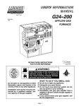
,,1752'8&7,21
352'8&7'(6&5,37,21
• A control panel assembly and all electrical controls for operation of the boiler, including a water temperature thermometer in circuit 1
Model FCX oil fired boiler utilizes a sealed combustion system that operates at a temperature at which
the flue products will condense. The flue products
temperature is so low that the unit is suitable for use
with PVC / Polypropylene flue pipes, which are offered as standard options for installation. Model FCX
is approved for installation with zero clearance to
combustible materials by Intertek Testing Services
to the UL Standard for Oil Fired Storage Tank Water
Heaters (UL 732).
• A manual water-mixing valve that can be motorized if desired
• A safety pressure relief valve
• An expansion tank
• A water circulating pump
• Complete internal water piping terminating in
connections for two independent water-heating circuits.
Model FCX is completely assembled and provides
standard parts as follows:
• Complete internal air piping terminating in a
connection to a coaxial flue/combustion air intake system.
• An enameled steel cabinet with thick insulation
• A completely unitized, thick shelled boiler with
combustion chamber and a heat exchanger
with a system of removable baffles
Standard options include:
• Coaxial balanced flue system components for
connection to the boiler to provide venting of
the flue products and combustion air intake.
• A stainless steel condenser, with condensate
drain
• A high efficiency, low emission, gun type oil
burner with combustion air fan, integral oil
pump, oil heater and primary control
2.20
5.55
34.6
2.20
34.4
5.98
8.94
17.7
34.0
34.4
39.1
2.28
23.7
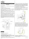
Front view
27.5
Side view
Rear view
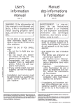
,1752'8&7,21
'(6,*1$7,212)&20321(176
21
20
19
18
17
22
14
3
24
1
2
1
16
2
View from above
26
17
18
19
21
22
25
3
15
4
14
7
5
23
13
20
6
12
8
8
9
11
10
Front view
&RQWURO3DQHO
&RQWURO3DQHO&RYHU
6DIHW\3UHVVXUH5HOLHI9DOYH
&RQGHQVHU
0DQXDO0L[LQJ9DOYH
&RPEXVWLRQ3URGXFW3UHVVXUH7HVW3RLQW
&RQGHQVHU,QVSHFWLRQ3RUW
&RQGHQVDWH'UDLQ
'UDLQ&RFN
%XUQHU$LU,QOHW3LSH
2LO%XUQHU
6DIHW\/LJKWDQG5HVHW%XWWRQ
6LJKW*ODVV
%RLOHU6KHOO
Rear view
3RFNHWVIRU:DWHU2YHUKHDWLQJ6DIHW\DQG7KHU
PRVWDW%XOEV7KHUPRVWDW
+HDWLQJ2XWSXW6HQVRU
%OHHG
)LUVW&LUFXLW+HDWLQJ2XWSXW
6HFRQG&LUFXLWKHDWLQJRXWSXW
&RPEXVWLRQ3URGXFWV)OXH
)LUVW&LUFXLW+HDWLQJ5HWXUQ
6HFRQG&LUFXLW+HDWLQJ5HWXUQ
:HOOIRU&RPEXVWLRQ3URGXFW2YHUKHDWLQJ7KHU
PRVWDW%XOE
3URWHFWLRQ3ODWHIRU(OHFWULFDO&RQQHFWLRQV%R[
&LUFXODWLQJSXPS
([SDQVLRQYHVVHO
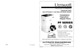
,1752'8&7,21
%2,/(523(5$7,21
Circuit heating
return
or
2nd circuit heating
output
1st circuit heating
output
Water is circulated through the boiler heat exchanger and condenser circuits where it is heated by the
combustion of the oil burner. Two independent water-heating circuits can be connected to the unit:
Combustion air is drawn into the oil burner by the
burner fan through the air intake hose connected to
the coaxial flue/combustion air intake separator
tube assembly. Heated air from combustion of the
oil burner cools as it passes through the boiler heat
exchanger, then the condenser. Cooled flue products exit the unit through the center of the flue/
combustion air separator tube assembly. Condensate from the flue products is drained from the bottom of the condenser into the condensate drain
tube, exiting the unit through the condensate drain
system..
• The first circuit passes through a three way
mixing valve incorporated into the boiler. This
valve can either be used manually as supplied
or driven by a regulator (option).
• The second circuit can supply another heating
circuit and/or a domestic hot water production
system.
,1752'8&7,21
352'8&767$1'$5'5$7,1*6
Ratings for Model FCX are provided in the following
table:
3HUIRUPDQFH3DUDPHWHU
8QLWV
3URGXFW5DWLQJ
Rated Output
BTUH
76,000
Rated Input
BTUH
81,250
Combustion Chamber Length
Inches
8.98
Combustion Chamber Diameter
Inches
11.5
Combustion Chamber Volume
Cu. Inches
915
Combustion Prod. Circuit Volume
Cu. Inches
3051
Flue Pressure Drop
Inches H2O
0.10
Psig
43.5
Max Heating circuit water temperature
Deg. F
176
Water Overheating Safety Thermostat Setting
Deg. F
230
Combustion Prod. Overheating Safety Thermostat Setting
Deg. F
248
Heating Circuit Water Capacity
Gallons
4.23
Primary Water Flow Rate (60/80 deg. C)
Gal/hr
254
Water Pressure Drop (at nominal flow rate)
MCE
1.4
Power Absorbed (with burner, without circulator)
KW
0.22
Packaged Weight
Lb.
267
Maximum Heating Service Pressure
Ratings are for the boiler when connected to standard option coaxial flue system components.
Electrical Power Supply
115 volts, single phase, 60 Hz
3.0 Amps FLA
Full Load Current
15 Amps
Max Fuse/ Circuit Breaker Size
',$0(7(52)3,3(&211(&7,216
&RQQHFWLRQ
'LDPHWHU
8QLWV
3.15 / 4.92
Inch
Water Heating Supply/Return
1
Inch
Domestic Hot Water or Second Heating Circuit
1
Inch
1 -1/2
Inch
Heating Water Drain
½
Inch
Air Bleed
3/8
Inch
Safety pressure relief valve
3/4
inch
Combustion Products
Condensate Drain
,,,167$//$7,21
23(1,1*7+(81,7
To open Model FCX to access for installation, and/
or service, follow these steps :
- Remove the control panel escutcheon molding
(2) by grasping it on both sides and pulling it
outward towards you and up. The escutcheon will
come free of the attachment clips leaving the control panel exposed.
- Remove the top cover of the unit (A) by lifting the
cover at the front and rear to free the attachment
clips, and then simply lift the cover straight up and
off.
- Remove the front panel attachment screws (P),
then pull the front panel (J) outward towards you
at the top to free it from the attachment clips. Lift
the panel up to free it from the lower attachment
pins, and simply lift the panel off.
A
2
P
J
/2&$7,212)7+(81,7
course, a significant part of the choice.
Model FCX is a free standing (floor mounted) appliance suitable for installation on combustible flooring. It is approved for installation with zero
clearance to combustible walls, ceiling, doors, etc
from the cabinet. Standard option coaxial flue components are suitable for installation with zero clearance to combustible materials.
While Model FCX can be installed in an enclosure
such as a closet, ventilation or other means must be
provided so that the enclosure temperature does
not exceed 113 deg. F (45 deg. C).
These are operating clearances and it is recommended that additional clearances be considered:
• Sufficient clearance should be provided in
back of the unit to facilitate installation and
maintenance of water, electrical, flue and condensate drain connections and components.
• Sufficient clearance over the top of the unit
should be provided to allow the top to be removed for service.
• Sufficient clearance from the front of the unit
should also be provided to facilitate adjustments and service.
There is no need for additional clearance to either
side of the unit since there is no access to the unit
from either side.
Alternative access measures such as doors, removable wall panels, etc. may be provided if desired.
Choosing the location should also take into account
the total flue length to the outdoors (See Flue Connection and Routing). In addition, the choice of location should consider the location of utilities such as
electrical supply and sewer access for condensate
drainage. Location and routing of water lines is, of
,167$//$7,21
)/8(&211(&7,216$1'5287,1*
3RO\SURS\OHQH39&
&RQFHQWULF
7HUPLQDO)RU)ODWRU6ORSLQJ5RRI
Connection of the coaxial flue/combustion air piping
system is in the back of the unit to the separator
tube assembly. The combustion products are vented from the boiler and condenser through the center of the coaxial tube, while the combustion air is
supplied through the outside ring of the coaxial tube.
Since Model FCX is a condensing boiler, flue products exiting the unit are relatively low temperature,
from 140 - 185 deg. F (60 - 85 deg C), and saturated
with humidity. Consequently, an airtight, corrosion
resistant flue system must be provided.
5HIHUHQFH &RORU
Various standard option flue piping components and
packages with which to create the flue system are
available.
N40.28393
Tile
N40.28394 Black
P6WUDLJKW+RUL]RQWDO)OXH.LW
9HUWLFDO
/HQJWK
,'
2'
42.5 inches
(1080mm)
3.15 inch
(80mm)
4.92 inch
(125mm)
42.5 inches
(1080mm)
3.15 inch
(80mm)
4.92 inch
(125mm)
Useful length under sleeve tile - 16.9 inches
(0.43 m)
3RO\SURS\OHQH39&
([WHQVLRQ
&RQFHQWULF +RUL]RQWDO
- joint fitting -
5HIHUHQFH
/HQJWK
N40.28399
38.6 inches
(980 mm)
P$QJOHG+RUL]RQWDO)OXH.LW
5HIHUHQFH
/HQJWK
,'
2'
N40.28397
19.7 inches
(500 mm)
3.15 inch
(80mm)
4.92 inch
(125mm)
N40.28398
39.4 inches
(1000 mm)
3.15 inch
(80mm)
4.92 inch
(125mm)
Useful length after assy. - 17.7 inches (0.45 m) or
37.4 inches (0.95 m)
5HIHUHQFH
V72.28414
,167$//$7,21
3RO\SURS\OHQH5RRI3ODWH
6OHHYH7LOHZLWK$GDSWDEOH&RXSOLQJ
5HIHUHQFH
6ORSH
&RYHULQJ
W\SH
&RORU
5HIHUHQFH
&RORU
N40.12165
25 - 45 deg
Tile
Tile
A90.12172
Black
N40.12166
35 - 55 deg
Tile
Tile
N40.12167
35 - 55 deg
Slate Shingle
Black
3RO\SURS\OHQH39&&RQFHQWULF(OERZ
- joint fitting -
45 ° bend
90 ° bend
5HIHUHQFH
&RORU
,'
2'
N40.28395
45 deg
3.15 inch
(80mm)
4.92 inch
(125mm)
N40.28396
90 deg
3.15 inch
(80mm)
4.92 inch
(125mm)
)DVWHQLQJFROODURSWLRQ
)LJ
5HIHUHQFH
1XPEHU
∅
PP
B00.29727
3
125
Collars are essential to bear the weight of the vertical extensions so that the boiler does not bear the
weight.
,167$//$7,21
7\SLFDOLQVWDOODWLRQH[DPSOHV
All flue-piping components must be assembled to
provide an airtight flue/ combustion air system.
The flue/combustion air system piping may be either
horizontal or vertical or a combination of both, observing the following:
Application of liquid soap over the flue pipes to be
joined will aid in assembly of the parts.
• The maximum unrestricted horizontal or vertical flue length shall not be more than 16.4 ft
(5 m).
Typical installation examples appear in the illustration that follow.
6WUDLJKW%DODQFHG)OXH&RQILJXUDWLRQ
• For each 90-degree elbow used in the flue system, subtract 3.3 ft (1m) from the total allowable length.
• For each 45-degree elbow used in the flue system, subtract 1.65 ft (0.5m) from the total allowable length.
1 in
• Horizontal runs of the flue system must pitch
down 3/4 inch per yard (2 cm per m) of length
towards the boiler to facilitate proper flue products condensate drainage.
2.8 ft
1,80 m
5.9 ft.
• Termination of a horizontal flue system shall
not be less than 5.96 ft(1.8m) above ground
unless other provisions are made to minimize
the likelihood of flue/combustion air intake
blockage.
• Do not place the flue terminal less than 3.3 ft.
(1 m) from a ventilation hole or opening in a
building.
• Termination of a vertical flue must provide at
least 12 inches (30cm) above the roof jack to
the combustion air intake collar.
Option: Straight Horizontal Flue Kit
• If there are two units in the installation with vertical flue systems, the termination of the systems must be separated by 16 inches (40cm).
$QJOHG%DODQFHG)OXH&RQILJXUDWLRQ
30 cm - 12 In.
mini
1 in
1,80 m
5.9 ft.
16 In.
40 cm
mini
Option: Angled Horizontal Flue Kit
,167$//$7,21
7\SLFDOLQVWDOODWLRQH[DPSOHVFRQW
/
/
/
/
/
/
Options:
- 1 90 deg concentric elbow
- 3 Concentric extensions
- 2 45 deg concentric elbows
- 1 concentric vertical terminal
- 1 sleeve tile roof flange
- 1 roof plate
Options:
- 1 90 deg concentric elbow
- Concentric extensions
- 1 concentric vertical terminal
- 1 sleeve tile roof flange
- 1 roof plate
PD[/ /IWP/IWP
/IWP≤IWP
PD[/ /IWP ≤IWP
,167$//$7,21
7\SLFDOLQVWDOODWLRQH[DPSOHVFRQW
90° elbow
90° elbow
45° elbow
45° elbow
View from above
View from above
rear boiler
rear boiler
/
/
/
/
Options:
- 1 90 deg concentric elbow
- 3 Concentric extensions
- 3 45 deg concentric elbows
- 1 concentric vertical terminal
- 1 sleeve tile roof flange
- 1 roof plate
Options:
- 1 45 deg concentric elbow
- 1 90 deg concentric elbow
- Concentric extensions
- 1 concentric vertical terminal
- 1 sleeve tile roof flange
- 1 roof plate
PD[/ /IWPIWP
≤IWP
PD[/ /IWP/IWP
/IWPIWP ≤IWP
,167$//$7,21
7\SLFDOLQVWDOODWLRQH[DPSOHVFRQW
90° elbow
45° elbow
view from above
rear boiler
1,80 m
5.9 ft
1 in
Options:
- 1 45 deg concentric elbow
- 2 90 deg concentric elbow
- 1 concentric extension
- 1 straight horizontal flue kit
&21'(16$7('5$,1&211(&7,21
Connection of the condensate drain piping system
is to the back of the unit beneath the flue/combustion air separator tube assembly. The condensate
drain tube provided in the unit is 1 - 19/32 inches (40
mm) O.D. to which the drain trap assembly supplied
with the unit may be connected. The condensate
drain outlet connection on the trap is 1 - 19/32 inches (40mm) O.D. to which standard 1 -1/2 inch trade size schedule 40 PVC pipe can be connected to
create the rest of the drain system. The drain system must pitch downward towards the sewer.
5
6
7
8
Note: The condensate will not likely require any specific water treatment because of condensate dilution
by normal wastewater use. If, however, local regulations require wastewater to have a neutral pH, a
condensate treatment tank can be installed
between the trap and the sewer.
,167$//$7,21
:$7(5&,5&8,7&211(&7,216
• Isolation valves may be used in the various circuits to facilitate boiler maintenance without
having to completely drain each circuit. NEVER place an isolation valve between a pressure relief device and a water tank.
Water circuit connections are made in the back of
the unit utilizing the four 1" male pipe thread couplings provided. Model FCX can be connected to various comfort heating water systems as well as to a
domestic hot water heating system if desired, observing that:
• An expansion tank must be provided in the
system to support an expansion of 6 % of the
total water capacity of all the circuits employed.
• Water circulating pumps provided in the various circuits must be large enough for each
circuit including the pressure drop of the boiler/
condenser in the unit. For optimum sound level
and power consumption, set the circulator to
the speed that is appropriate for the installation
flow rate and pressure drop.
• Safety pressure relief valve must be connected
to the drain.
• The water pressure gauge (not supplied) has
to be fitted outside the unit.
9DULRXVW\SLFDOZDWHUFLUFXLWVDUHLOOXVWUDWHGEHORZ
&RQQHFWLRQWRDVLQJOHKHDWLQJFLUFXLW
Rc1
& &
0
VM1
M
%RLOHU
3UHVVXUHJDXJH
& 5DGLDWRUFLUFXLW
90 VWFLUFXLWPL[HUYDOYH
'F VWFLUFXLWKHDWLQJRXWOHW
5F VWFLUFXLWKHDWLQJUHWXUQ
Dc1
C
&RQQHFWLRQWRDKHDWLQJFLUFXLWZLWKDGRPHVWLFKRWZDWHUSURGXFWLRQV\VWHP
Rc1
& &
0
VM1
%RLOHU
3UHVVXUHJDXJH
& 5DGLDWRUFLUFXLW
90 VWFLUFXLWPL[HUYDOYH
'F VWFLUFXLWKHDWLQJRXWOHW
5F VWFLUFXLWKHDWLQJUHWXUQ
M
Dc1
B
C
Ss
P3
& 'RPHVWLFKRWZDWHUSUHSDUD
WLRQFLUFXLW
3 'RPHVWLFKRWZDWHUSXPS
%
'RPHVWLFKRWZDWHUSURGXFWLRQ
V\VWHP
&
6V 'RPHVWLFKRWZDWHUVHQVRU
,167$//$7,21
Various typical water circuits (cont)
&RQQHFWLRQWRDGRXEOHKHDWLQJFLUFXLW
&
0
Rc1
&
Rc2
VM1
M
P2
Dc2
Dc1
&
Sd
VM2
C
%RLOHU
3UHVVXUHJDXJH
& 5DGLDWRUFLUFXLW
90 VWFLUFXLWPL[HUYDOYH
'F VWFLUFXLWKHDWLQJRXWSXW
5F VWFLUFXLWKHDWLQJUHWXUQ
&
3
90
'F
5F
6G
8QGHUIORRUKHDWLQJFLUFXLW
QGFLUFXLWKHDWLQJFLUFXODWRU
QGFLUFXLWPL[HUYDOYH
QGFLUFXLWKHDWLQJRXWSXW
QGFLUFXLWKHDWLQJUHWXUQ
+HDWLQJRXWSXWVHQVRU
&RQQHFWLRQWRDGRXEOHKHDWLQJFLUFXLWZLWKDGRPHVWLFKRWZDWHUSURGXFWLRQV\VWHP
&
0
%RLOHU
3UHVVXUHJDXJH
& 5DGLDWRUFLUFXLW
Rc1
VW
& 90 FLUFXLWPL[HUYDOYH
Rc2
VM1
'F VWFLUFXLWKHDWLQJRXWSXW
5F VWFLUFXLWKHDWLQJUHWXUQ
M
P2
Dc2
& 8QGHUIORRUKHDWLQJFLUFXLW
QGFLUFXLWKHDWLQJFLUFXODWRU
90 QGFLUFXLWPL[HUYDOYH
'F QGFLUFXLWKHDWLQJRXWSXW
5F QGFLUFXLWKHDWLQJUHWXUQ
6G +HDWLQJRXWSXWVHQVRU
Dc1
& 3
Sd
C
B
VM2
Ss
&
P3
)8(/2,/6833/<&211(&7,216
Flexible fuel oil supply and return lines are supplied
with the unit, and connected to the oil burner. Lines
are terminated with 3/8-inch reverse flare fittings for
connection of the supply and return lines from the
fuel oil tank. When connecting the lines, a 10-micron
Gerber oil filter must be installed in the oil supply line
to minimize burner contamination.
& 'RPHVWLFKRWZDWHUSURGXFWLRQ
FLUFXLW
3 'RPHVWLFKRWZDWHUSXPS
%
'RPHVWLFKRWZDWHUSURGXFWLRQ
V\VWHP
6V 'RPHVWLFKRWZDWHUVHQVRU
,167$//$7,21
(/(&75,&$/&211(&7,216
:$51,1*(/(&75,&$/6+2&.+$=$5'
',6&211(&77+(32:(56833/<%()25($77(037,1*(/(&75,&$/
,167$//$7,212)7+(81,7
down caused by an unrelated electrical circuit fault,
the unit and any related electrical components
should be connected to a separate branch circuit
specifically dedicated for that purpose.
Electrical power and control connections are made
to pigtail leads that exit through a hole in the right
rear of the unit (facing the front of the unit).
The power connections must be made in a Listed
junction box that is not provided with the unit. All wiring should conform to the National Electrical Code
and any applicable local codes and standards. To
minimize the likelihood of a heating system shut-
The control circuit connections can be in-air splices
made to pigtail leads provided. Control circuit connections are NEC Class 2, intended for connection
to a typical room thermostat.
/(*(1'
W : White
B : Blue
Gy : Grey
Br : Brown
Bk : Black
O : Orange
R : Red
Dk. G : Dark green
Lt. G : Light green
9+]HDUWK
/(*(1'
/ 3KDVH
1 1HXWUDO
0$ 2Q2IIVZLWFK
(+ 6XPPHU:LQWHUVZLWFK
76(2YHUKHDWVDIHW\FXWRXW
DTXDVWDW
75&$GMXVWDEOHWKHUPRVWDW
76))OXHJDVVDIHW\FXWRXW
WKHUPRVWDW
9 2QOLJKW
9 %XUQHUVDIHW\VKXWGRZQ
OLJKW
& %XUQHUFRQQHFWRU
) )XVH$
5 5HOD\
7 0DLQWUDQVIRUPHU
YROWV
&& &LUFXODWLQJSXPS
1RWHV
$(OHFWULFSRZHUOHDGVIDFWRU\SURYLGHGDWULJKWUHDURIXQLW3HUPDQHQWO\ILHOGVSOLFHILHOGSURYLGHGSRZHU
FLUFXLWOHDGVLQ1(&MXQFWLRQER[
%&RQWUROFLUFXLWOHDGVIDFWRU\SURYLGHGDWULJKWUHDURIWKHXQLWDUHYROW1(&FODVVIRUFRQQHFWLRQWRDURRP
WKHUPRVWDW
,167$//$7,21
Route the factory supplied main power pigtail leads
through the connector from inside the unit and secure the connector clamp on the wires.
The hole in the right rear of the unit is a large flat
oval. Mount a Listed 2 x 4 inch, "HandiBox" type
junction box over the oval hole in such manner that
part of the hole is left open. When installing the junction box, center the box vertically over the oval hole
by using the center knockout in the box. Install a ½
inch trade size cable connector or insulating
bushing in the knockout. Secure the box with screws
as required.
Install a second cable or conduit connector in another knockout in the box for the power wiring system
as required. Connect the power wires and grounding conductors to the pigtail leads in the box using
Listed wire connectors and install a cover.
Route the factory supplied control circuit pigtail
leads through the open part of the oval hole from inside the unit. Connect the room thermostat wires to
the control circuit pigtail leads using a suitable
Class 2 wiring connection method.
The open part of the oval hole can be either above
or below the junction box depending upon the choice of wire routing. The Class 2 control circuit leads
will exit the open part of the hole.
833(5/()75($5&251(52)81,7 (Facing rear of unit)
1
3
2
5
4
-XQFWLRQER[
0DLQ3RZHU3LJWDLO/HDGV
8QLW8SSHU%DFN3DQHO
2YDO+ROH
&RQWUROFLUFXLW3LJWDLO/HDGV
,,,67$5783$1'23(5$7,21
35(67$57),1$/6<67(0&+(&.
freeze solution if appropriate. Open any shutoff valves in the system.
Before starting normal operation of the boiler and
heating system, perform the following final installation procedures:
• Fill the condensate drain trap with water.
• Leak-check the flue/combustion air system to
minimize the likelihood of leakage.
• Leak-check the fuel oil supply system and
open any fuel shut-off valves.
• Leak-check the entire water system, repairing
any leaks that may be found.
• Re-check the power and control circuit connections THEN replace all cabinet access panels.
• Fill the entire water system with water, treated
as desired for the application, including anti-
• Energize the electrical power circuit to the unit.
67$5783$1'23(5$7,21
After completing the pre-start final system checks,
the system can be started and run through start-up
checks and adjustments as required.
7
3
8
4
+
5
6
6WDUW6WRS6ZLWFK
6XPPHU:LQWHU6ZLWFK
&LUFXODWRUFRQWUROLQWVLGHWKHERLOHU
%RLOHU7HPSHUDWXUH&RQWURO7KHUPRVWDW
%RLOHU7HPSHUDWXUHDGMXVWHGEHWZHHQ
GHJ)&
:DWHU2XWOHW7HPSHUDWXUH7KHUPRPHWHU
&LUFXLW
1
2
:DWHU2YHUKHDWLQJ6DIHW\7KHUPRVWDW
%XUQHU&XWRXW
&RPEXVWLRQ3URGXFW2YHUKHDWLQJ6DIHW\7KHU
PRVWDW
%RLOHU6KXWGRZQ
%XUQHU6DIHW\'HYLFH/LJKW
6ORWIRU$GGLWLRQDO&RQWURO
has expired, the burner will start.
To start the boiler, first make sure the room thermostat is set at a high enough temperature to be
closed so that any external water circulating pumps
are running. Turn the boiler On-off switch to the
"ON" position, and set the Boiler Temperature Control thermostat to its maximum temperature setting.
Reduce the Boiler Temperature Control thermostat
setting to make sure the boiler stops properly when
controlled by that thermostat. Increase the room
temperature thermostat setting to make sure that
the circulating pump(s) stop properly.
Turn the Summer-winter switch to "WINTER". This
will start the internal circulating pump. After the start
time delay set on the oil burner (for the oil heater)
67$5783$1'23(5$7,21
$'-867,1*7+(2,/%851(5
While the oil burner is adjusted at the factory, it is recommended that the operating characteristics of the
burner be determined at start-up and readjusted if
necessary. Run the unit long enough at the burner
maximum firing rate to make sure the burner has
reached a stable maximum operating temperature.
THEN, check the burner and adjust as follows:
7
Check to determine that the smoke spot number
does not exceed 0.5 with a Bacharach control. Adjust the burner as required to achieve this maximum.
6
M
Check to determine that the CO2 rate is from 12 - 13
percent and that there is no CO production. Adjust
the burner as required to achieve this operating characteristic.
Measure the temperature of the flue gas exiting the
unit to determine that it does not exceed 250 degrees F (120 C).
7
N
Combustion inspection can be carried out on the
unit through the hole (item N) provided in the inspection port (item 7). Be sure to replace the washer
(item M) and the test point screw (item 6) properly
after inspection.
M
6
&+(&.,1*7+(6$)(7<'(9,&(6
- Flame monitoring :
At the time of start-up, check the safety and control
devices as follows :
- Thermostats :
• Check to make sure that the burner shuts
down properly upon the deactivation or disconnection of the flame monitoring device or interruption of the flow of fuel,
- Safety Pressure Relief valve :
• Check to see that the thermostat bulbs are
correctly positioned in their housings. This is
essential to provide temperature sensing to
facilitate burner shut-down in the event of
overheating,
• Check the safety pressure relief valve in the
heating circuit for proper operation.
,90$,17(1$1&(
It is recommend that the boiler and flue/combustion
air system be inspected and maintained annually by
a qualified technician.
',6&211(&7$//(/(&75,&$/&,5&8,76%()25(6(59,&,1*7+(81,7
&/26($1<,62/$7,219$/9(67+$70$<%(,17+(:$7(56<67(0
6+872))7+()8(/2,/6833/<,)6(59,&,1*7+(%851(5
plate by removing the screws in the rear and lifting.
Remove the control panel cover screws and remove
the control panel cover.
To gain access to the inside of the unit, first remove
the control panel cover escutcheon by grasping it on
both sides and pulling directly outward towards you
and up. Remove any front panel screw(s) and remove the front panel by pulling the top out towards you
and then lifting up to free the bottom from the mounting pins. Remove the top cover by simply pulling it
up. Remove the electrical terminal block protection
The water can be bled from the unit by opening the
drain-cock on the base of the boiler shell using the
tool supplied.
&/($1,1*7+(%2,/(56+(//
• Remove the screws (B) from the cast-iron boiler
shell cover (C)
C
B
• Remove the flue outlet baffle (D)
B
• Remove the combustion baffles (E)
• Clean the inner walls of the boiler shell
C
• Reassemble all the parts the way they were removed, positioning the flue outlet (D) with its
centering screw (P) towards the front of the boiler, then positioning the boiler shell cover (C)
arrow marker opposite the centering screw (P)
B
D
P
E
14
• Replace the screws (B) in the boiler shell cover.
14
&/($1,1*7+(&21'(16(5
• Remove the wing nut (F) from the condenser
top cover (G) and remove the cover
• Remove the condenser access plug (7)
F
• Clean the condenser tubes (H) using a bottle
brush or similar tool
G
I
G
• Observe that the combustion products can flow
freely in the condenser tubes
F
4
• Replace the condenser access plug (7) and the
top cover (G), making sure that the seal (I) is
properly positioned when replacing the cover
H
4
7
• Make sure that the seal (I) on the cover and the
access plug is in good condition.
6
NOTE: If after cleaning the condenser, the temperature of the flue gasses still exceeds 250
deg. F (120C), perform a boiler check.
B
0$,17(1$1&(
%851(50$,17(1$1&(
if necessary. Cleaning and adjustment is always appropriate during periodic inspection.
Once adjusted properly, regular maintenance of the
oil burner is not generally required. A routine examination of the burner should include examination of
the burner fan and nozzle for dirt and the spark electrodes for proper clearances. Replace the fuel filter
If burner firing rate adjustment is required, follow
instructions in "Adjusting the Oil Burner".
$/:$<6&+(&.)25$1'&255(&7$1<)8(//($.6
$'',7,21$/&20321(170$,17(1$1&(
ler have any water or fuel leaks (leaks may produce
a risk for safety and shorten the lifespan). If it becomes frequently necessary to add water to maintain
pressure in the installation, even though no leaks
have been discovered, perform an expansion tank
check.
Check to see that the safety and regulation devices
(safety relief valve, air bleed valve, control box components, etc.) are operating properly. Check also to
see that the condensate drain siphon is clean. If necessary, remove the bottom of the siphon, clean it,
replace it and then refill the siphon it with water. Also
check to see that neither the installation nor the boi-
(;3$16,217$1.35(,1)/$7,2135(6685(&+(&.
pre-inflation pressure of the tank after totally
bleeding any air from the installation.
Reduce the pressure in the heating installation by
opening the drain cock or the safety valve until the
pressure gauge reading is less than 7 - 8 psig (0.5
bar)
Check the pressure in the expansion tank and if necessary bring it back up to pressure. Replace the
tank if the membrane is punctured (water present in
the inflating valve)
H
To optimize the efficiency of the expansion tank:
• Adjust its pre-inflation pressure in line with the
installation. The pressure must correspond to
the static height of the installation (H), the
height between the highest point of the
installation and the expansion tank, as
expressed in bars where 10 meters in height =
1 bar.
Water inlet
Inflating valve
Membrane
Max vessel
volume
Dilated water
volume
Pressure rises as the
air is compressed
• Adjust the filling pressure of the installation to
a value greater than 3 psig (0.2 bar) above the
&20%867,21352'8&7)/8(
cess water in the condensate trap when cleaning is
completed.
Examine the flue/combustion air system for leaks
and obstructions. Leaks can generally be detected
by the appearance of condensate stains on the outside of the pipes. Replace any damaged seals if necessary. The flue/combustion air pipe can be
cleaned with running water, if necessary, providing
that the water flow is not too great to be drained
through the condensate drain system. Leave the ex-
0$,17(1$1&(
&+$1*,1*$7+(50267$7257+(7+(5020(7(5
remove the thermostat. Replace the thermostat with another, routing the bulb capillary the
same way as the original, replacing the bulb
properly into the pocket as far as possible.
Replacement of the thermostats or the thermometer
requires removal of the bulb from its location and the
control from the control box.
• The bulb for the Boiler Temperature Thermometer is located on the first circuit heating output tube. Remove the bulb from the tube,
remove the thermometer mounting screws in
the control box and remove the thermometer.
Replace the thermometer with another, routing
the bulb capillary the same way as the original,
replacing the bulb on the tube properly and as
securely as possible.
• The bulb for the Combustion Product Overheating Thermostat is located in a well provided in
the condenser access plug/inspection port.
Remove the combustion test point plug and
washer from the inspection port to free the
thermostat bulb, and remove the bulb from the
well. Remove the thermostat mounting screws
in the control box and remove the thermostat.
Replace the thermostat with another, routing
the bulb capillary the same way as the original
and replacing the bulb properly into the well as
far as possible. Replace the combustion test
point plug and washer in the inspection port,
securing the bulb in place.
• The bulbs for the Boiler Temperature Control
Thermostat and the Water Overheating Safety
Thermostat are both located in pockets on the
side of the boiler shell. To change either, remove the bulb from the pocket, remove the thermostat mounting screws in the control box and
23
23
7
7
M
M
923(5$7,1*)$8/76
During the course of seemingly normal operation,
there may be operating faults experienced in the
system. Some of the more common faults that may
be encountered are:
%851(5)$8/76+87'2:1 - The burner may
shut down for any of several reasons, at which point
the burner safety device light (red) on the control panel will be ON and the there will be a green fault indicator light lit on the oil burner. This may be caused
by a loss of fuel oil (tank empty?), a fouled oil spray
nozzle in the burner, or perhaps a fouled or faulty
flame sensor. To attempt a re-start after correcting
any burner problem and the fuel supply is assured,
push the reset button on the burner. The burner
should re-start after the preset time delay period expires.
29(5+($7,1* 6$)(7< 7+(50267$7 6+87
'2:1 - Opening of either the Water Overheating
Safety Thermostat or the Combustion Product
Overheating Thermostat will result in an oil burner
shutdown. In either case, the burner safety device
light (red) on the control panel WILL REMAIN OFF,
and the green fault indicator light on the oil burner
will REMAIN OFF. The only way to tell if either
device has opened is to check electrically or check
the position of the reset button, located under the
screw cap over each device.
• The Water Overheating Safety Thermostat
may open if the water temperature exceeds
230 deg. F (110C) in the boiler. ONLY a faulty
Water Temperature Control causes this
shutdown. The Water Temperature Control
probably requires replacement.
• The Combustion Product Overheating Safety
Thermostat may open if combustion products
exceed 250 deg. F (120C). This may require
adjustment of the oil burner to the proper firing
rate or cleaning the boiler and/or condenser.
After correcting any fault, either thermostat must be
manually reset by removing the screw cap on top
and depressing the reset button.
SEPTEMBRE 2001
MPI - P.O. BOX 3408 PRINCETON, NEW JERSEY 08543 - PHONE 800/524-1102 (NJ 732/329-0900) FAX 732/329-0904