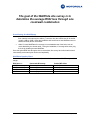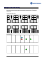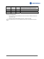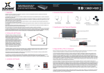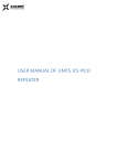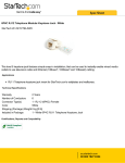
1
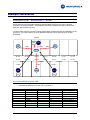
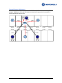
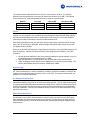
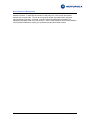
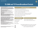
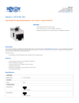
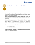
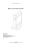
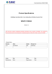
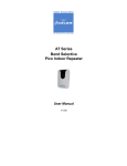
Installing Motorola MC-802 Wireless WallPlate
The MC-802 Wireless WallPlate is a new addition to the PowerBroadband product family. This
application note details specific topologies and best practices used for the installation of the
Wireless WallPlate. To set the proper context, we’ll start with a short introduction of the T3
PowerBroadband system. Key concepts used throughout the document are covered in Appendix
A. Best practice recommendations include a limited site survey procedure to determine
installation density.
T3 PowerBroadband System
The T3 system from Motorola is designed primarily for hospitality, but useful in any high density
MDU type installation. The T3 PowerBroadband Switch is installed in the central phone room of a
hotel or MDU, where it is cross connected onto the existing telephone wiring. The centrally
installed T3 PowerBroadband Switch has 25 ports for downstream CPEs, and 2 x GigE uplink
ports.
Two different types of remote CPEs are supported. The CPEs are installed in a hotel guest room
or any RJ11 jack within the MDU. The CPEs are designed as a wall plate form factor, and draw
operating power over the same telephone wire pair as broadband backhaul. Due to the form
factor, the name “WallPlate” is used to describe the CPE.
m2 WallPlate
The m2 WallPlate is a managed, Ethernet-only device. It has two 10/100Mb Ethernet
ports to connect access devices. 802.1Q VLANs and QoS can be managed throughout
the system, from the 25-port switch to each wall plate port.
MC-802 Wireless WallPlate
The Wireless WallPlate is just what it sounds like. It is a line-powered WallPlate with an
integrated 802.11b/g radio. The Wireless WallPlate has the same two 10/100Mb
Ethernet ports as the m2 WallPlate. All configuration, status and statistics for the
Wireless WallPlate are provided by the centrally installed T3 Switch.
Key features:
•
Line power up to 600 meters* for the m2 WallPlate, and 300 meters
for the MC-802 Wireless WallPlate. Line power is transparent to and
compatible with analog telephone service on the same wire
• One wire pair
• Optimized for IPTV and other advanced networking
*600m is the limit of line power. If using an optional external power supply, T3 will deliver
broadband up to 1500m
The T3 system is comprised of the following components. In addition to the primary products
listed, filters are required for extra telephones that share the same wire pair.
Motorola, Inc
Page 1 of 12
•
•
•
Name:
Motorola P/N:
Model:
T3 PowerBroadband Switch, RoHS
558975-001-00
45225
•
•
•
Name:
Motorola P/N:
Model:
m2 Ethernet WallPlate, RoHS
549478-001-00
45101
•
•
•
Name:
Motorola P/N:
Model:
MC-802 Wireless WallPlate, RoHS
557925-001-00
45010
T3 PowerBroadband Switch and m2/MC-802 WallPlates
TABLE OF CONTENTS
Installation Routine.............................................................................................3
Example Lite-Site Survey ...................................................................................5
Example Installation ...........................................................................................7
Example One: RoomLoss = 20dB.............................................................................................. 7
Example Two: RoomLoss = 15dB.............................................................................................. 8
Appendix A ........................................................................................................10
Motorola, Inc
Page 2 of 12
Installation Routine
The goal of the installation can be stated relative to received signal strength (RSSI):
•
•
-70dBm signal strength or better in every room
Maximum of three co-channel cells within the carrier detect range
Perfect non-overlapping cell coverage is impossible to achieve. Read Appendix A for a
description of the carrier detect range and its effect on media access.
The network architect can control three variables when deciding where and how to install the
Wireless WallPlate network. Each variable has a different degree of effect on the overall network
performance.
•
Physical placement is an important determinant of success. Because of the fast
installation routine, WallPlate placement is easy to adjust onsite during the installation.
•
Channel assignment is used to create overlapping coverage cells and reduce the cochannel cell overlaps. In most countries, channels 1 – 11 are available; where only
channels 1, 6, 11 are non-overlapping for 802.11g modulation.
•
Transmit power can be adjusted to fine-tune the signal strength and reduce some cochannel interference. The WallPlates can be adjusted in 1dB increments from 14dBm to
1dBm. NOTE: Transmit power alone will not overcome an installation with too great a
density.
Full Site Survey
The goal of any wireless site survey covers two key purposes:
•
Determine the number of APs required for adequate RSSI into each hotel guest room.
•
Determine where and how to backhaul and power the AP installed in the hotel corridor.
Because the hotel guest is in the room, and not in the hallway, co-channel interference between
hallway-installed APs is usually not considered during a site survey. The focus is on pumping
enough power into the rooms to connect the hotel guest. When APs are installed in the hotel
corridor, mistakes are nearly impossible to correct. Adding an additional AP to cover a weak area
of the hotel is extremely difficult. Typical corrective action usually involves a higher gain antenna.
This is often ineffective if poor coverage is due to obstructions or multi-path reflections. Thus, an
extensive and expensive site survey is required.
Lite-Site Survey
With the Wireless WallPlate, the possible install locations include each room in the hotel.
Because of the fast installation, corrective action is very easy to execute if additional WallPlates
are required. Thus the site survey can be done quickly or not at all, with adjustments made
during the installation time.
Since the same construction material is used throughout the property, a complete room to room
site survey is unnecessary.
Motorola, Inc
Page 3 of 12
The goal of the WallPlate site survey is to
determine the average RSSI loss through one
room/wall combination
Provisioning the WallPlates
•
Order the number of WallPlates according to the RSSI loss through one room/wall. If the
floor material is the same as the walls e.g. concrete, then the vertical loss will be similar
(usually +3dB to +6dB). Offset the installation with each floor so that WallPlates are not
stacked vertically above one another.
•
Order 5% extra WallPlates for coverage in non-standard areas of the hotel; such as
rooms blocked by an elevator shaft. During the installation, if coverage holes exist, plug
the hole by installing an extra WallPlate.
Once the typical RSSI loss through a hotel is determined, site surveys at similar hotels become
unnecessary as the same plan can be used repeatedly.
WallPlate Density Chart
Based on the RSSI loss from one room/wall, order the indicated number of WallPlates, plus 5%
margin.
RSSI loss is…
>30dB
>20dB and <30dB
>10dB and <20dB
<10dB
Motorola, Inc
Horizontal WP density
One every three rooms
One every four rooms
One every four to six rooms
One every eight rooms
Vertical WP offset
Install offset one room
Install offset two rooms
Install offset three rooms
Install offset four rooms
Page 4 of 12
Example Lite-Site Survey
Many hotels are built with mirror image rooms to speed the construction time. The example
below was taken from a real 250 room hotel constructed of concrete block on all interior and
exterior walls.
TV/desk
TV/desk
TV/desk
TV/desk
TV/desk
TV/desk
TV/desk
TV/desk
TV/desk
TV/desk
TV/desk
TV/desk
TV/desk
TV/desk
Layout of the hotel rooms
Measured RSSI
a
A
B
D
C
Motorola, Inc
Page 5 of 12
Location
Transmitter
RSSI
-28dBm
Loss
42dB
A
a
B
C
D
-32dBm
-60dBm
-55dBm
-83dBm
-80dBm
4dB
32dB
27dB
55dB
52dB
Note
Antenna to air conversion loss. Measured at 1m
using integrated Intel Pro2200B/G in Dell Laptop.
Same room, with AP mounted 12” from floor
Down one floor
One room over
Across the hall, over one room
Two rooms over
Note some interesting results:
1. We can predict the measured RSSI three rooms over would be -105dBm, well below the
carrier detect range.
2. RSSI loss is approximately 25dB per room/wall. Vertical loss is 32dB.
Based on the RSSI loss from A to B, this installation would require one WallPlate for every four
rooms.
Motorola, Inc
Page 6 of 12
Example Installation
E x a m p l e O n e : Ro o m L o s s = 2 0 d B
Hotels generally use dense wall material to reduce audible noise from one room to another.
Concrete is a common material. 20 to 25dB RF loss can be measured through concrete hotel
walls, but actual results may vary.
The worst case would be a client PC sitting approximately midway between two WallPlates on the
same floor. From this location, the client would be within the carrier detect range of multiple
WallPlates.
Rm 205
B
Ch-1
D
Ch-1
H
Ch11
-60dBm
-70dBm
F
Ch11
-70dBm
client
Rm 201
Rm 203
Rm 205
Rm 207
Rm 209
Rm 211
Rm 213
Rm 202
Rm 204
Rm 206
Rm 208
Rm 210
Rm 212
Rm 214
-112dBm
-70dBm
G
Ch-6
E
Ch-6
A
Ch11
-112dBm
I
Ch-1
C
Ch-6
Anticipated RSSI in Room 205
•
•
All WPs at maximum Tx power
Connected to WallPlate H in room 105 on channel 11
Will See AP …
A
B
C
D
E
F
G
H
I
Motorola, Inc
At RSSI …
-112dBm
-60dBm
-112dBm
-70dBm
-70dBm
-70dBm
-112dBm
-60dBm
-112dBm
On Channel …
11
1
6
1
6
11
6
11
1
Co-Channel
No
No
No
No
No
Yes
No
Yes
No
Notes
Outside Range
Different channel
Outside Range
Different channel
Different channel
In range, same ch
Outside Range
Connected
Outside Range
Page 7 of 12
RF Media Access
The client wireless driver will connect with the WallPlate that has the strongest RSSI. Regardless
of which WallPlate is selected by the client driver, the co-channel interference will be one other
WallPlate, very low co-channel interference and well within the bandwidth of the RF medium.
Redundancy
Five total WallPlates are within -70dBm of the client. Thus, if one WallPlate fails, the client will
always maintain a high datarate connection to the network.
E x a m p l e T w o : Ro o m L o s s = 1 5 d B
Using the same installation density, let’s look at the resulting RSSI loss when the loss per
wall/room combination is 15dBm and the floor loss is 5dB greater than the horizontal.
B
Ch-1
D
Ch-1
H
Ch11
-50dBm
-60dBm
-60dBm
F
Ch11
client
Rm 201
Rm 203
Rm 205
Rm 207
Rm 209
Rm 211
Rm 213
Rm 202
Rm 204
Rm 206
Rm 208
Rm 210
Rm 212
Rm 214
-95dBm
G
Ch-6
A
Ch11
-60dBm
E
Ch-6
-95dBm
I
Ch-1
C
Ch-6
Note that WallPlates A, G, C, and I are all approximately -95dBm, right at the edge of the carrier
detect range of -94dBm. Additionally, WPs two floors up will also appear within the carrier detect
range.
Motorola, Inc
Page 8 of 12
Transmit Power Adjustment
In this case, we reduce the transmit power of all WallPlates by 6dBm. Note the resulting RSSI
changes: WallPlates A, G, C and I fall below the carrier detect range and will not present cochannel interference with the client.
B
Ch-1
D
Ch-1
H
Ch11
-56dBm
-66dBm
-66dBm
F
Ch11
client
Rm 201
Rm 203
Rm 205
Rm 207
Rm 209
Rm 211
Rm 213
Rm 202
Rm 204
Rm 206
Rm 208
Rm 210
Rm 212
Rm 214
-101dBm
G
Ch-6
A
Ch11
Motorola, Inc
-66dBm
E
Ch-6
-101dBm
I
Ch-1
C
Ch-6
Page 9 of 12
A pp en di x A
Media Access Control
802.11 wireless devices are half-duplex; meaning they cannot transmit and receive
simultaneously. Access to the media is controlled by carrier detect media access - listening on
the specified frequency, and transmitting in a time when no other signal is present. Using carrier
detect many devices can share the same RF medium. Adding CTS/RTS further increases the
number of co-channel devices; although CTS/RTS itself reduces the total bandwidth available to
the client.
Carrier Detect Range
Carrier detect media access operates within the maximum distance that a signal will be received
above the noise floor of a neighboring device. This is the carrier detect range. When laying out
the network topology, it is important to factor the carrier detect range. For the Wireless WallPlate,
the carrier detect range is -94dBm, the sensitivity level of the receiver. Note that the carrier
detect range is not a physical distance; however, some attempt is made in this document to
correlate physical distances to the important RF domain since we all live in the real world.
Pathloss
Pathloss is defined as the ratio of transmit to received power, normally expressed in dB. It can be
measured by subtracting the receive signal strength in dBm from the transmit signal power
in dBm. Pathloss calculations are always one-way; from a transmitter to a receiver. In theory,
the return path should be the same, but does vary. It is not uncommon to see asymmetrical
pathloss.
It is desirable for a client device to have a low pathloss to more than one WallPlate. The client
driver normally associates with the AP having the strongest signal (lowest pathloss).
Because of the material used in hotel construction, pathloss is difficult to mathematically
calculate. It must be measured. While this implies a comprehensive site survey; in fact, some
basic assumptions can be made from a relatively simple site survey using only the received
signal strength (RSSI).
Signal Loss in Material
bed
RoomLoss in dB =
(Loss through wall material) + (Loss in free space in room)
TV/desk
Most RF pathloss discussions focus on the losses in free space, without consideration for the
attenuation through different wall material. In fact, the attenuation that occurs in a 27cm concrete
block wall is nearly equal to the signal loss over 6 meters in free space! (using the formula
Pathloss in dB = (Loss at 1 Meter) + α * 10 * LOG(Distance in meters) + Xσ). To simplify this
process; we can combine the loss through free space in one room with the loss through one wall
material and arrive at a value that can be applied cumulatively through multiple rooms.
bed
bath
Motorola, Inc
Page 10 of 12
The material used in walls and floors can vary from one property to another. For example,
different chemical formulations of concrete can cause loss variations up to 5dB. The following
chart is based on RF engineering studies and can be used as a general guide.
Material
Concrete block
Red Brick
Drywall
Loss (dB)
15 - 20
15 – 25
3–6
+
Room (dB)
6
6
6
=
RoomLoss (dB)
21 – 26
21 – 31
9 - 15
Tools
Many software site survey tools are readily available for a charge or free. Using the RoomLoss
method; it is only required to use a software tool that displays all visible BSS (AP MAC address)
and their associated RSSI and channel. NetStumbler is one such tool. Cisco CB21 PCMCIA
cards also provide this information using the included software suite.
While many manufacturers may use the same wireless radio chipset, implementations can vary
quite a bit. RF sensitivity on the board, antenna design and antenna cable losses all vary from
one laptop model to another.
Since we are primarily interested in the signal delta (its loss factor), the actual RSSI reading is not
quite as important. Validate the laptop sensitivity before beginning the installation, using this
procedure:
1. Set the Wireless WallPlate in site survey mode by loading the special software, or turn on
the WallPlate and set the transmit power to 14dBm
2. Align the WallPlate in a vertical position with the flared tabs on the top and bottom
3. Place the laptop at 1meter away from the WallPlate AP on the same vertical height. The
RSSI of the WallPlate should be between -26dBm and -30dBm.
Redundancy
It is desirable for an installation to provide adequate signal coverage with the loss of any single
AP. Passive redundancy, or rather redundancy by design, requires an installation in which every
location receives adequate signal levels from two or more APs. This must be balanced with the
potential for co-channel interference.
Co-Channel Interference
Because of the media access method described above, each AP or client will reduce the
bandwidth available to any other AP or client on the same channel. This co-channel interference
is expected and predicted by carrier detection and media access. While we cannot control where
a client will be located, we can control the co-channel interference between any two WallPlates
during the installation. Selecting the installation density to control co-channel interference is the
point of this document.
Multi-Path Reflections
RF signals are like rolling a football; they take a funny bounce. Sometimes, a strong signal can
be received in one location; while movement of only a few feet can result in much lower signal.
Each WallPlate AP has two antennas with receive diversity. Simply stated, the signal from any
other transmitting device is received by both antennas, and the stronger signal is passed to the
wireless driver.
Motorola, Inc
Page 11 of 12
Deviations and Exceptions
As always, there will be exceptions. For example, a hotel may not use the same material
between all rooms. It could be that concrete is used every four or five rooms; with drywall
between the concrete walls. This can be very good for proper signal attenuation, but some
upfront thinking is required. In general, using the RoomLoss method with an Install Time
adjustment will lead to faster or no site surveys. Look for creative ways to use the fast installation
of the Wireless WallPlate to simplify your processes and provide a better network.
Motorola, Inc
Page 12 of 12