1
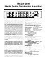
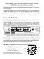
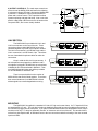
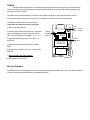
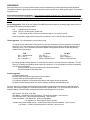
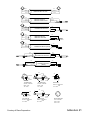
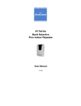
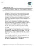
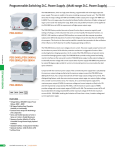
MADA-2000
Owners Manual
Rev A
7/1/99
9181 Chesapeake Drive • San Diego, CA 92123 • (858) 560-4162 • (858) 560-1923 Fax
MADA-2000
Media Audio Distribution Amplifier
Lift
Mic
Output dBm
Unbal
Lift
Line
Mic
Unbal
Line
Mic
Unbal
Line
Lift
Lift
Mic
Unbal
Line
Mic
Unbal
Line
Lift
Media Audio Distribution Amplifer
Lift
Mic
Unbal
Line
Lift
Mic
Line
Unbal
Lift
Mic
Unbal
Lift
Line
Mic
Unbal
Line
Mic
Unbal
Line
Lift
MADA-2000
Monitor Level
-6
0 +6 +12 +18
Monitor Headset
Output
Why put up with the necessity of placing numerous
unsightly microphones on a podium, that block the sight
lines to the speaker, just to provide recording feeds to
print and TV reporters. With the MADA-2000 there only
needs to be one microphone to provide that recording
feed. The Media Audio Distribution Amplifier is an audio
mixing & distribution amplifier that is capable of supplying
audio to reporters and sound cameramen at press
conferences. The amplifier/mixer portion of the MADA2000 provides two (2) microphone and one (1) line inputs
which in turn feed the mixed signal to ten fully insolated
microphone or line level outputs. Each output is equipped
with assorted standard connectors assuring easy access
by the media. Other uses include: “on locations”
recording, interfacing large audio systems at conventions,
and isolating signals in applications where AC ground
currents might present problems.
The MADA-2000 features up to 60db of gain... low output noise (-90db)...low distortion (less than .25% THD at
full rated output) and flat frequency response(+/-0.5db
24-18kHz).
The MADA-2000 amplifier is self-contained with it’s own
power supply and features differential balanced inputs
with Op-Amp transformer isolated outputs. Isolation
between outputs is well over 100db. All outputs, including headset monitoring jack, monitor level control and
Bar LED level indicators are located on the front panel.
Each of the ten (10) outputs are independently selectable to line or microphone level with each having selectable ground isolation to solve ground current problems.
The rear panel contain’s XLR input connectors, phantom power control, mixing level controls and LED system level indicators. Link in/link out connectors are also
mounted on the rear panel, enabling cascading MADA2000’s to allow for multiple input and outputs.
The MADA-2000 is designed for standard EIA 19” rack
mounting and requires 3.5” of vertical rack space.
Specifications
Type: Audio Distribution Amplifier
Frequency Response: +/- .5db - 24 Hz to 18kHz
Inputs: Two balanced microphone inputs
One balanced line input
Input Source Impedance: Microphone 1k ohms
Line 7.5k ohms
Number of Outputs: Ten (10) Line/Mic selectable
Link Connection:
600 ohms 0dbm
Maximum Gain:
60db, continuously variable
Maximum Output:
+20dbm into 600 ohms
Nominal(system) Output:
+4dm into 600 ohms (Line)
-60dbm into 1k ohms (Mic)
Output Source Impedance:
600 ohms (line)
220 ohms (mic)
Distortion (THD): .25% at maximum rated output
Signal to Noise Ratio (=4dbm):
90db, 24 hz - 18khz
600 ohms source, 600 ohm load,
unweighted
Isolation Between Outputs: 100db, 30 hz - 18khz
Output Metering: LED Bar Graph:
Green(below 6db), Yellow (+15db),
Red (+21db)
Output Monitoring:
Headphone Jack 600 to 1500 ohms stereo
Connections:
Inputs: XLR female 3 pin
Outputs: XLR male 3 pin, 1/8” mini phone,
¼” phone
Dimensions: 19” w x 3.5” h x 4.5” d
47.5cm x 8.75cm x 11.25cm
Weight: 6lbs (2.7 kg)
Power Requirements:
106 - 130 VAC, 50-60Hz 25 watts
Congratulations on your purchase of the Communications Company
MADA-2000 Media Audio Distribution Amplifier!
The MADA-2000 is an audio press patch (aka newsbridge), which allows distribution of up to three audio sources to
multiple press recording devices. It may also be used as an audio distribution amplifier and an isolation device in
difficult grounding sites.
The MADA-2000 functions as both a mixer pre-amplifier and distribution amplifier. The mixer is comprised of two
Microphone (150 Ω) inputs and one Line(600 Ω) input. The MADA-2000 will mix the 3 input signals, then amplify
that signal to either -56dBm for microphone or +4dBm for line level and distribute that signal to the ten outputs. The
mixing stage of the MADA-2000 has a maximum of 60 dB of gain available. The distribution section is equipped
with ten transformer isolated outputs for microphone and line. Each output is provided with a 3 pin Male XLR
receptacle, a 1/4” phone jack , a 1/8” mini phone jack, a ground lift switch and a microphone/line level selector
switch.
How to use the MADA-2000
The MADA-2000 is a very simple and forgiving device to use. Just plug in the source microphone(s), adjust the
output level using the built in LED meters then plug in your recording devices.
1) INPUT CONTROLS: There are three independent inputs on the rear of the MADA-2000. Two are Microphone
level (150 Ω, XLR-F) and these are designed to have a podium microphone directly plugged into them. There are
individually selectable phantom power (+15 Vdc) available on each of the microphone inputs. The Line input (600 Ω,
XLR-F), is designed to accept a feed from a mixer or house sound system.
LINK OUT
LINE
LEVEL
LINE IN
MIC 2
LEVEL
SYSTEM LEVEL INDICATOR
HIGH
OK
MIC 1
LEVEL
MIC 2
MIC 1
POWER
LINK IN
MIC 1
PHANTOM
POWER
MIC 2
PHANTOM
POWER
ON
ON
OFF
OFF
LOW
105-125VAC, 50/60Hz
1/4A SLOW-BLOW FUSE INSIDE
MADA-2000 MEDIA AUDIO DISTRIBUTION AMPLIFIER
S.N.
WARNING:
210-250VAC, 50/60Hz
DO NOT REMOVE COVER. NO USER SERVICEABLE PARTS INSIDE.
REFER SERVICING TO QUALIFIED PERSONNEL.
TO REDUSE RISK OF ELECTRIC SHOCK, DO NOT EXPOSE
THIS APPLIANCE TO RAIN OR MOISTURE.
1/8A SLOW-BLOW FUSE INSIDE
AVIS: RISQUE DE CHOC ELECTRIC. NE PAS OUVRIR.
NOTE: All three inputs can be used simultaneously. Keep in mind that each input needs to be set at a level
comparable to the other two, so that one is not louder, as there is no master volume control on the unit.
2) LEVEL SETTING: On the left rear of the MADA-2000 there are 3 LED’s: High(red), OK(green), Low(yellow). The
LED’s are provided as an aid to set the output signal level. Adjust the rear input level control(s) to the point at which
the OK (green) LED is on solid. This will indicate that the output level will be in the -6 to +6dB range which, under
normal usage, is an appropriate output signal level. It is normal that the Red (high) and Yellow (low) LED’s will
flicker as the signal level varies. Make sure the Red LED is not constantly on, as this would indicate an overdrive
situation or the Yellow LED is not constantly on, as this would indicate a low signal situation.
3) OUTPUTS: On the front of the MADA-2000 are ten identical outputs, with the following features:
Select the output level required, plug into the desired
connector, and the signal will then be distributed to that user.
MADA-2000
Media A
1/8" / 3.5mm Jack
Line or Mic
Output Selector
XLR (M)
Jack
1/4" / 6mm Jack
Mic
Line
Lift
Mic
Unbal
Line
Lift
1 ea XLR 3 pin Male jack
1 ea 1/4” / 6.25mm 3 conductor TRS Phone jack
1 ea 1/8” / 3.5mm 3 conductor TRS Mini jack
1 ea Microphone (150 Ω) or
line (600 Ω) output selector
1 ea Three position grounding Switch
Ground
Lift Switch
4) OUTPUT CONTROLS: The main output controls are
on the front of the MADA-2000 and feature the following.
A red power indicator LED that is lit when the MADA-2000
is powered. A headphone output jack with 8 watts of
power and a volume control. This is provided to allow
system monitoring and help with setup. Also on the front
panel is a Bar Graph LED’s that mirror’s the action of the
rear panel LED’s, but is more visually detailed.
Headset Volume
Control
Output dBm
Unbal
Lift
Power Indicator
Monitor Level
Output Level
Meter
-6
0 +6 +12 +18
1/4" Headset
Phone Jack
Monitor Headset
Output
LINK SECTION
The MADA-2000 is provided with Link In and
Link Out connectors on the rear of the unit. These
connections allow multiple MADA-2000 units to be
cascaded together to provide more outputs if needed.
The Link Out connection is a XLR Male 3 pin and the
Link In connection is a XLR Female 3 pin. This allows
the use of standard microphone cables to make the
connections.
LINK OUT
There is no practical limit on the number of
MADA-2000’s that can be linked together. There have
been several instances of ten MADA-2000’s linked
without signal loss or audio degradation occurring.
LINE IN
MIC 2
LEVEL
MIC 1
LEVEL
MIC 2
HIGH
OK
MIC 1
LINK IN
MIC 2
PHANTOM
POWER
MIC 1
PHANTOM
POWER
ON
ON
OFF
OFF
LOW
MADA-2000 MEDIA AUDIO DISTRIBUTION AMPLIFIER
LINK OUT
Keep in mind the link circuit is not two way. If
two microphones are plugged in to MADA #1 and a
microphone is plugged in to MADA #2, the microphone
in MADA #2 will not be distributed in MADA #1. However MADA #2 and all further units will be provided a
mix of both MADA #1 and MADA #2.
LINE
LEVEL
SYSTEM LEVEL INDICATOR
LINE
LEVEL
LINE IN
MIC 2
LEVEL
MIC 1
LEVEL
MIC 2
HIGH
OK
MIC 1
LINK IN
MIC 2
PHANTOM
POWER
SYSTEM LEVEL INDICATOR
MIC 1
PHANTOM
POWER
ON
ON
OFF
OFF
LOW
MADA-2000 MEDIA AUDIO DISTRIBUTION AMPLIFIER
LINK OUT
LINE
LEVEL
LINE IN
MIC 2
LEVEL
SYSTEM LEVEL INDICATOR
HIGH
OK
MIC 1
LEVEL
MIC 2
MIC 2
PHANTOM
POWER
MIC 1
LINK IN
MIC 1
PHANTOM
POWER
ON
ON
OFF
OFF
LOW
MADA-2000 MEDIA AUDIO DISTRIBUTION AMPLIFIER
MOUNTING
The MADA-2000 is supplied in a standard 19” wide 3.5” high rack mount format. It’s 7.5” depth will fit into
any standard EIA 19” rack . The unit also includes two handles that provide for ease of handing and protection of
the connectors plugged into the front panel. If you plan to install the MADA-2000 in a transportation case, keep in
mind the unit is only 7.5” deep, but potentially needs 4” of clearance on the front of the unit. The case should be
ordered in a short depth model, to facilitate access to the rear connections and allow viewing of the rear mounted
input level LED’s.
POWER
The MADA-2000 is powered by an on-board power supply that is wired from the factory at 120Vac 50/60Hz.
The power supply can be easily changed to operate on 240Vac 50/60Hz by moving jumpers and exchanging a fuse
located on the main PC board.
The MADA-2000 can be ordered from our factory in the 240Vac configuration, just notify sales at time of order.
If you need to make a change from 110/120Vac to 220/240Vac in the field, here are the steps involved:
1) UNPLUG the MADA-2000 from all power and
remove the A/C cable from the rear of the unit.
P1
Fuse
120V - 1/4 amp
250V - 1/8 amp
2) Remove the top of the unit.
3) With the output connections toward you, the power
supply is located on the lower PC board on the left
side. It will look similar to this diagram.====== >>>>
Jumpers
(110/120V)
JP1 & JP2
F1
WARNING !
JP1
120V
DO NOT INSTALL 240V
JMPR UNLESS BOTH 120V
JMPRS ARE REMOVED
JP2
JP3
120V
4) Unsolder and remove jumpers JP1 and JP2, labeled 120V.
C29
R43
240V
R93
R93
Jumper
(220/240V)
JP3
C29
CAUTION !
TO REDUCE THE RISK OF FIRE, REPLACE "F1"FUSE
ONLY WITH THE SAME TYPE AND RATING
105-125V OPERATION 1/4A 250V MDL
210-250V OPERATION 1/8A 250V MDL
5) Install and solder a new jumper at JP3, labeled
240V.
6) Replace the existing F1 fuse with a 1/8 amp, 250V
MDL fuse.
VR2
T11
VR1
C33
7) Do not remove any other jumpers.
C31
C32
8) Re-Install the top of the unit.
Mic/Line Diagram’s
In Addendum #1 there are samples of connection wiring and standard patch cable wiring. These are industry standard
wiring conventions and the MADA-2000 is designed around them.
GROUNDING
Almost all cases of hum or noise in audio systems can be traced back to ground loops and grounding problems.
The MADA is subject to ground loops, as are all electronics units that have an on-board power supply. Some simple
suggestions are:
First and most important suggestion - Don’t clip the ground leg off the AC cord. The removal of the ground leg
from a AC connector will substantially increase the chance of getting electrical shock, We don’t recommend or
advocate removing the ground leg, as there is little proof this action will consistantly eliminate ground loop
hum.
Second Suggestion - Each of the ten outputs of the MADA has a three position grounding toggle switch, which is
provided to help reduce grounding problems.
Left
- unbalances the connection
Center - lifts pin 1 off the system ground buss
Right - is the normal position: connection is balanced and pin 1 is routed to ground
Move the grounding toggle switch between the 3 positions to see if it will eliminate the problem.
Third suggestion - Do a full diagnostic of the system wiring.
A) Unplug all input cables and re-insert them one at a time checking to see if the noise/hum is caused by
that input. If so, look at the how the cable is wired and confirm that it is wired to industry standard microphone pin wiring. This is important because the MADA is designed and wired to the following industry
standard wiring conventions:
XLR
Pin 1 = Shield/Ground
Pin 2 = Hot “+”
Pin 3 = Negative “-”
¼” Phone
Tip = Hot “+”
Ring = Negative “-”
Sleeve = Shield/Ground
1/8” Mini
Tip = Hot “+”
Ring = Negative “-”
Sleeve = Shield/Ground
B) Unplug all output cables and then re-insert each one at a time, until the noise/hum reappears. This will
allow you to identify the offending cable or piece of equipment. If it is not possible to remove the offending
hum, then try the following:
1) Put an isolation transformer between the item and the MADA.
2) Look at the patch cord being used.
Fourth suggestion A) Keep all cables short.
B) Keep cables of the same signal type and level together.
C) Keep cables of different signal levels apart.
D) If cables are pigtailed - keep exposed conductors and copper as short as possible.
E) Make sure that all patch cables are wired to industry standards. (See addendum #1)
Since the subject of grounding could fill a large book, the above suggestions are a attempt to help with trouble
shooting. We strongly suggest you research this audio area in greater depth. For more in-depth information on
audio grounding, we have found the following books and technical papers to be of value:
AES Journal - Vol 43 #6, June 1995
Glen Ballou - Handbook for Sound Engineers, The Audio Cyclopedia - ISBN 0240803310
Don & Carolyn Davis - Sound System Engineering - ISBN 0240803051
Rane Corporation - Tech Note #102 - Analog I/O Standards
- Tech Note #110 - Sound System Interconnection
Yamaha (Gary Davis & Ralph Jones) - Sound System Reinforcement Handbook - ISBN 0881889008
( Jon Eiche) - A Guide to Sound Systems for Worship - ISBN 079350029X
1
2
2
1
3
3
RED
RED
BLACK
BLACK
Balanced XLR to XLR
SHIELD
1
SHIELD
2
3
RED
RED
Balanced XLR to
Balanced TRS Phone
BLACK
SHIELD
1
BLACK
SHIELD
2
3
RED
RED
Balanced XLR to
Unbalanced TS Phone
BLACK
SHIELD
1
BLACK
SHIELD
2
3
RED
RED
Balanced XLR to
Balanced 1/8" Mini
BLACK
SHIELD
1
BLACK
SHIELD
2
3
RED
RED
Balanced XLR to
Unbalanced Phono (RCA)
BLACK
SHIELD
SHIELD
Balanced TRS Phone
Unbalanced TS Phone
SHIELD
Balanced TRS Phone
Unbalanced Phono
(RCA)
TIP
TIP
RING
BLACK
SHIELD
RED
RED
BLACK
SHIELD
RED
RED
BLACK
BLACK
BLACK
SHIELD
TIP
RING
SLEEVE
SLEEVE
1/8" TRS PLUG
1/4" TRS PLUG
SLEEVE = GROUND
SLEEVE = GROUND
RING = LOW
RING = LOW
TIP = HIGH
TIP = HIGH
SLEEVE
RCA PLUG
SLEEVE = GROUND &
LOW
TIP = HIGH
TIP
TIP
1
2
3
SLEEVE
SLEEVE
1/8" TS PLUG
1/4" TS PLUG
XLR 3 PIN PLUG
SLEEVE = GROUND &
LOW
TIP = HIGH
SLEEVE = GROUND &
LOW
TIP = HIGH
PIN 1 = GROUND
Courtesy of Rane Corporation
PIN 2 = HIGH
PIN 3 = LOW
Addendum #1