1
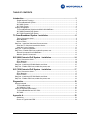
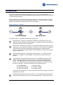
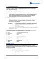
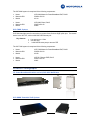
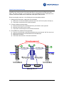
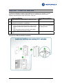
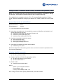
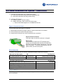
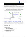
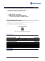
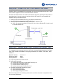
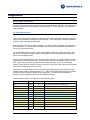
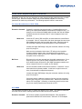
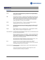
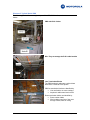
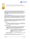
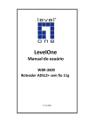
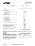
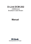
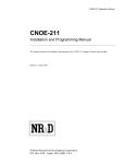
Installing Motorola Private Broadband Networks
Motorola Private Broadband Networks (PBN) extend layer-2 Ethernet over telephone grade wiring
at varying distances from 600 meters to 3000 meters. Each product has value-added features,
designed for specific applications and markets.
Network managers will be familiar with common networking tasks such as 802.1Q VLANs, QoS,
Access Control Lists, SNMP, etc. Understanding the physical installation routines is critical to a
successful installation. The installation tools and procedures are not common with Ethernet
structured wiring.
This paper describes the steps required to install Motorola Private Broadband Networks over
ordinary telephone grade wire pairs. “Private Broadband Networks” is a key term. All the
Motorola PBN products are designed for wiring that is not connected to the public telephone
network. By limiting the products to private wire networks; advanced value-added features such
as line power and optimized bandwidth can be added to the product line.
Three product families are covered in this app note:
•
•
•
T3 PowerBroadband System
XLP-6800 Extended PoE System
XLP-7000 Extended PoE System
Contact your Motorola sales representative for additional application notes and documentation
available for the Private Broadband Networks.
Motorola, Inc
Page 1 of 24
TABLE OF CONTENTS
Introduction .........................................................................................................3
Simple Network Topology ....................................................................................................... 3
T3 PowerBroadband System .................................................................................................. 5
XLP-6800 System ................................................................................................................... 5
XLP-7000 System ................................................................................................................... 6
Product Photographs .................................................................................................................. 6
T3 PowerBroadband Switch and m2/MC-802 WallPlates ...................................................... 6
XLP-6800 Extended PoE System........................................................................................... 6
XLP-7000 Extended PoE System........................................................................................... 7
T3 PowerBroadband System - Installation .......................................................8
Type of Connectors Used ....................................................................................................... 8
Bill of Materials........................................................................................................................ 8
Note on Filters......................................................................................................................... 9
Step One – Install the Switch and Cross connects ..................................................................... 9
Install the T3 Switch and termination blocks........................................................................... 9
Install the Cross Connects .................................................................................................... 11
Step Two - Install the WallPlate ................................................................................................ 12
Step Three - Enable xDSL lines, enable line power, test ......................................................... 13
General Commands for all WallPlates.................................................................................. 13
Wireless Specific Commands ............................................................................................... 13
XLP-6800 Extended PoE System - Installation ...............................................14
Type of Connectors Used ..................................................................................................... 14
Bill of Materials...................................................................................................................... 14
Note on Filters....................................................................................................................... 14
Step One - Install the XLP-6824 Switch and client ................................................................... 15
Step Two - Enable xDSL lines, enable line power, test ............................................................ 15
XLP-7038 Extended PoE System - Installation ...............................................17
Type of Connectors Used ..................................................................................................... 17
Bill of Materials...................................................................................................................... 17
Note on Filters....................................................................................................................... 17
Step One - Install the XLP-7038 Switch and client ................................................................... 18
Step Two - Enable xDSL lines, enable line power, test ............................................................ 18
Diagnostics .......................................................................................................19
Wire pair shorted....................................................................................................................... 19
T3 PowerBroadband ............................................................................................................. 19
XLP-6824/XLP-7038 ............................................................................................................. 20
Less than expected performance.............................................................................................. 21
T3 PowerBroadband and XLP-7000..................................................................................... 21
XLP-6800 .............................................................................................................................. 21
Appendix A ........................................................................................................23
Definitions ............................................................................................................................. 23
Photos of Typical Hotel PBX................................................................................................. 24
Motorola, Inc
Page 2 of 24
Introduction
All products share a common operating system, CLI syntax, web UI, and SNMP MIBs. In all
cases, 802.1Q VLANs and QoS can be managed through the entire network from the core switch
to each remote Ethernet port.
An important feature in common with all products is line power. The remote client device (also
called a CPE) is line powered from the core switch installed in a central wiring closet. Pay close
attention to the difference in line power function for each product.
Simple Network Topology
In the diagram above, components of the network topology are:
A
B
1
2
Motorola Switch. This is the “concentrator” installed in a central wiring closet. Each
product family has a different switch port density. The Switch provides the management
interface for all features on the remote CPE.
Motorola CPE. Although the term CPE is not used in Motorola product literature, this is a
common term in the industry for this device. Unlike other “CPE”s however; the Motorola
CPEs operate by line power, and provide advanced features to enable enterprise
services. In the T3 product family; CPEs are called WallPlates, to match the form factor
of the product design.
Upstream Ethernet network. Each Motorola Switch (A) has 1, 2 or 4 Ethernet uplink
ports; either 10/100Mb, or 10/100/1000Mb. Use these ports to connect to the core
network.
Premises wiring. The premises wiring must be UTP - unshielded twisted pair. In the
case of T3; a single wire pair is required, and can be shared with analog telephone
service. XLP-6800 requires two or four wire pairs, not shared with analog telephone
service. XLP-7000 also cannot be shared with analog telephone, but requires only one
wire pair for operation. The maximum distances over premises wiring is:
T3 PowerBroadband:
XLP-6800 Extended PoE:
XLP-7000 Extended PoE:
up to 600m (2000ft)*
up to 3000m (10,000ft)
up to 1500m (5,000ft)
*600m is the limit of line power. If using an optional external power supply, T3 will deliver
broadband up to 1500m
3
Dowstream Ethernet network or Ethernet devices. XLP (extended line power) products
provide 802.3af compliant PoE power on the downstream ports. Connect devices such
Motorola, Inc
Page 3 of 24
as wireless access points and IP cameras to the CPE (B). T3 does not provide PoE on
the downstream Ethernet ports.
Motorola, Inc
Page 4 of 24
T3 PowerBroadband System
The T3 system is designed primarily for hospitality, but useful in any high density MDU type
installation. The centrally installed T3 PowerBroadband Switch has 25 ports for downstream
CPEs, and 2 x GigE uplink ports.
Two different types of remote CPEs are supported.
m2 WallPlate
The m2 WallPlate is a managed, Ethernet-only device. It has two 10/100Mb Ethernet
ports to connect with access devices. 802.1Q VLANs and QoS can be managed
throughout the system, from the 25-port switch to each wall plate port.
MC-802 Wireless WallPlate
The Wireless WallPlate is just what it sounds like. It is a line-powered WallPlate with an
integrated 802.11b/g radio. The Wireless WallPlate has the same two 10/100Mb
Ethernet ports as the m2 WallPlate.
Key features:
•
Line power up to 600 meters* for the m2 WallPlate, and 300 meters
for the MC-802 Wireless WallPlate. Line power is transparent to and
compatible with analog telephone service on the same wire
• One wire pair
• Optimized for IPTV delivery
*600m is the limit of line power. If using an optional external power supply, T3 will deliver
broadband up to 1500m
The T3 system is comprised of the following components. In addition to the primary products
listed, filters are required for extra telephones that share the same wire pair.
•
•
•
Name:
Motorola P/N:
Model:
T3 PowerBroadband Switch, RoHS
558975-001-00
45225
•
•
•
Name:
Motorola P/N:
Model:
m2 Ethernet WallPlate, RoHS
549478-001-00
45101
•
•
•
Name:
Motorola P/N:
Model:
MC-802 Wireless WallPlate, RoHS
557925-001-00
45225
XLP-6800 System
XLP systems are designed for low density, enterprise networks. The XLP-6824 has 4 UTP wire
ports for connection to remote clients; and 4 x 10/100Mb Ethernet uplink ports. The remote
devices are the XLP-6802, a two port Ethernet switch with 2 x 10/100Mb Ethernet ports with full
802.3af PoE on both ports.
Key features:
Motorola, Inc
•
•
•
•
Line power up to 3km
Two or Four wire pair
2 x 802.3af Ethernet ports per remote CPE
Up to 75Mbps symmetrical
Page 5 of 24
The XLP-6800 system is comprised of the following components:
•
•
•
Name:
Motorola P/N:
Model:
XLP-6824 Master for PowerBroadband PoE, RoHS
552681-001-00
43114
•
•
•
Name:
Motorola P/N:
Model:
XLP-6802 Client, RoHS
552679-001-00
43002
XLP-7000 System
(not released as of 01/01/09. Available for beta evaluation)
XLP-7038 has eight ports for connection to remote clients, and one GigE uplink port. The remote
device is the XLP-701, with one 802.3af PoE Ethernet port.
Key features:
•
•
•
Line power up to 1.5km
One wire pair
1 x 802.3af Ethernet port per remote CPE
The XLP-7000 system is comprised of the following components:
•
•
•
Name:
Motorola P/N:
Model:
XLP-7038 Master for PowerBroadband PoE, RoHS
553552-001-00
43128
•
•
•
Name:
Motorola P/N:
Model:
XLP-701 Remote PSE, RoHS
553521-001-00
43001
P r o d u c t P h o t o g r ap h s
T3 PowerBroadband Switch and m2/MC-802 WallPlates
XLP-6800 Extended PoE System
Motorola, Inc
Page 6 of 24
XLP-7000 Extended PoE System
Motorola, Inc
Page 7 of 24
T3 PowerBroadband System - Installation
1) Install the switch in the central telephone room
a) Install switch and other network devices in equipment rack
b) Interconnect the switch with the premises telephone wiring
2) Install the CPE devices
a) Install filters on all other phones
b) Enable line power, test
Type of Connectors Used
The T3 system employs three types of connectors.
1)
2)
3)
4)
DB9 straight wired serial connector used for console connections on the Switch
RJ45 connectors are used for Ethernet devices
25-pair RJ21 connectors are used on the Switch to provide 25 downstream UTP wire ports
One RJ11 connector is used on the remote WallPlate for Line-in, and one for a filtered phone
port
a) xDSL and Power must be on pins 2-3
b) pins 1-4 are passed through the WallPlate
RJ-21 Connector
RJ-11 Line-In Connector on WallPlate
Pins 2 and 3 are line 1
Pins 1 and 4 are line 2
Pins 1 and 26 are wire pair 1
Pins 25 and 50 are wire pair 25
Bill of Materials
In addition to the Motorola T3 products, additional third party equipment is required.
Motorola Item Description
T3 PowerBroadband Switch
m2 Ethernet WallPlate
MC-802 Wireless WallPlate
RJ11 filter, inline
P/N
558975-001-00
548478-001-00
557925-001-00
552689-001-00
12VDC regulated p/s, US
12VDC regulated p/s, UK
12VDC regulated p/s, EU
552305-001-00
552307-001-00
552306-001-00
Third Party Item Description
Siemens connectorized block p/n S66M2-5W-TP
25-pair RJ21 Male-Male telco cable, ~3m to 5m
Ethernet cables, 2m (for CO equipment and in-room)
Motorola, Inc
Qty Required
One for every 25 end points
One for each end point
One for every 4 to 6 rooms
One for every extra phone on the same
wire pair (WallPlate includes one
integrated filter)
Purchase a few for diagnostics
Purchase a few for diagnostics
Purchase a few for diagnostics
Qty Required
One for every T3 Switch
Two for every T3 Switch
As needed
Page 8 of 24
Cross connect wire spool, 300m
19" Equipment Rack
Misc (AC power strip, wire management, etc)
UPS or line conditioning power
Aggregation Layer2 Ethernet Switch
One spool for ~100 rooms, as needed
As needed
As needed
As needed
As needed
Note on Filters
Only Motorola filters can be used when line power is enabled. Typical ADSL type filters do not
have enough filtering capability.
S t e p O n e – I n s t al l t h e S w i t c h an d C r o s s c o n n e c t s
Install the T3 Switch and termination blocks
Install the Switch in a standard EIA-19 equipment rack using the provided mounting ears. Install
other network equipment such as routers and Ethernet switches.
Termination blocks should be located close to the existing Room Termination blocks to facilitate
installation of the cross connect wires.
Connect an RJ21 Amphenol cable between the LINE side connector on the Motorola T3 Switch
and the Left side of the new termination block.
Connect an RJ21 Amphenol cable between the PHONE side connector on the Motorola T3
Switch and the Right side of the new termination block. The PHONE connector will carry line
Power + xDSL + telephone toward the Motorola WallPlate.
New Termination Block installed
Siemens S66M2-5W-TP or similar
Motorola, Inc
Page 9 of 24
25-pr Amphenol
LINE
25-pr Amphenol
PHONE
Motorola T3 Switch
Motorola, Inc
Page 10 of 24
Install the Cross Connects
If doing a hotel installation, identify the line 1 wire pair. The recommended procedure is to begin
replacing cross connects at the room termination block, moving back to the PBX termination
block. The reason is simple: In most cases, the room termination blocks are marked with room
numbers; whereas the PBX block is marked with cable pairs or PBX port IDs.
Remove and replace each line 1 wire following this recommended procedure:
1) Starting at the Room block, replace the wire termination
a) Remove the “old” wire termination (leave the rest of the “old” wire in place until step 3)
b) Punch down a new wire on the same termination
2) Connect the New termination block
a) Route the new wire pair to the Motorola block, punch down on the right side
b) Mark the block with the room number
c) Punch down a new wire pair on the left side of the block
3) At the PBX block, replace the wire termination
a) Trace the “old” wire back to its PBX termination point, removing the “old” wire as you go
b) Route the new wire from the Motorola block to the PBX block
c) Remove the “old” wire
d) Punch down the new wire on the same termination
3
Motorola, Inc
2
2
1
Page 11 of 24
S t e p T w o - I n s t al l t h e W al l P l at e
The Motorola WallPlate is designed to be installed over an existing RJ11 wall jack. In cases
where this is not possible; install the WallPlate next to the telephone jack, and route the
telephone cable through the small “mouse hole” in the side.
1)
2)
3)
4)
m2 Ethernet WallPlate
Install bracket over existing 70mm x 114mm RJ11 wall
jack
Install 150mm RJ11 cable between existing RJ11 jack
and bottom mounted RJ11 on WallPlate
Snap cover containing circuit board onto the bracket
• Using your finger, pull down the RJ11 cable so that it
doesn’t coil around the crystal on the bottom of the
PCB
• Align the bottom connector first, then with a slight
angle, snap the top connector in place
If extra security is desired, install 2 set screws into plastic
cover
MC-802 Wireless WallPlate
Same
Same
Attach WallPlate to the plastic
bracket using the provided 8x32
self-tapping screws.
Pictorial of m2 Ethernet WallPlate Installation
1
3
4
2
Motorola, Inc
Page 12 of 24
S t ep Th re e - E n a b l e x D S L l i n e s, en a b l e l i n e p o w e r, t e st
NOTE: Do not enable line power until filters have been installed on all telephones sharing
the wire pair. If line power is enabled without a filter, the phones will ring.
For a detailed list of commands, refer to the T2 or T3 Command Reference guide or T3 User
Guide. Details are available for configuring IP address, ACL, SNMP, VLANs, QoS, SNTP, IGMP,
etc.
General Commands for all WallPlates
Default IP address:
Default user name:
Default password:
192.168.1.3
admin
<blank>
1) Login using telnet or the serial console
2) Issue these commands (note: do not enable line power until after filters are installed on all
phones that share the wire pair)
a) interface dsl config port(1-25) max-down 75 max-up 10
b) interface dsl power enable port(1-25)
c) interface remote enable port(1-25)-(1-2)
3) Use these commands to monitor the system
a) show interface dsl status
b) show interface dsl statistics
c) show syslog messages level trace
4) Once filters are installed, line power can be enabled
a) Interface dsl po en portX
Review the diagnostics and monitoring section at the end of the document for explanation of the
line monitoring parameters.
Wireless Specific Commands
1) Create a WLAN Profile
a) wifi wlan profile add <SSID>
2) Assign the profile to a WLAN (16 supported per radio)
a) wifi wlan config wlanX-Y profile <SSID>
b) wifi wlan enable wlanX-Y
3) Enable a radio
a) interface wireless enable radioX
Where,
<SSID> is your selected SSID name
X is any dsl port, 1-25
Y is any of 16 WLANS per radio, 1-16
Note: Ranges can be used to specify additional DSL ports and/or WLANs
Motorola, Inc
Page 13 of 24
XLP-6800 Extended PoE System - Installation
1) Install the XLP-6824 switch in the central wiring closet
a) Install switch and other network devices in equipment rack
b) Interconnect the switch with the premises wiring
2) Install the CPE devices
a) Enable line power, check line status
b) Enable PoE power, check remote PoE device status
i) Note the XLP-6802 supports 2 x 10/100Mb PoE devices
Type of Connectors Used
The XLP-6824 uses three types of connectors:
1) DB9 straight wired serial connector used for console connections on the Switch
2) RJ45 connectors are used for Ethernet devices
3) Keyed terminal connector are used for premises wire connections
RJ-11 Premises Connector
Keyed Terminal Connector
From left to right, the pins are numbered 1 through 8
Where used
This connector is used on the UTP premises wiring
Pins 2 and 3 are used for xDSL and Power
between the XLP-6824 switch and the XLP-6802 client.
Note that the XLP-6800 system requires two or four wire
pairs for operation. To maximize performance and PoE
power at 3km, use all four wire pairs.
Bill of Materials
In addition to the Motorola XLP products, additional third party equipment is required.
Motorola Item Description
XLP-6824 Extended PoE Switch
XLP-6802 PoE client
P/N
552681-001-00
552679-001-00
Third Party Item Description
Ethernet cables, 2m (for CO equipment and in-room)
19" Equipment Rack
Misc (AC power strip, wire management, etc)
UPS or line conditioning power
Aggregation Layer2 Ethernet Switch
Qty Required
One for every 4 end points
One for each end point
Qty Required
As needed
As needed
As needed
As needed
As needed
Note on Filters
The XLP system is not compatible with telephone signals on the same wire pair. Therefore, filters
are not necessary.
Motorola, Inc
Page 14 of 24
S t e p O n e - I n s t al l t h e X L P - 6 8 2 4 S w i t c h a n d c l i e n t
Install the Switch in a standard EIA-19 equipment rack using the provided mounting ears. Install
other network equipment such as routers and Ethernet switches.
Premises termination with the XLP-6824 is normally done by directly punching the wire pairs to a
termination block. No cross connect is required since the XLP system is not compatible with
telephone wiring in the same wire pair.
1) Install a jumper wire (2pr or 4pr) between the keyed connector and the premises wiring
a) Two or Four wire pairs per keyed connector, depending on the available premises wire
pairs
2) Install a jumper wire between the end-point termination and the key connector
1
2
S t e p T w o - E n a b l e x D S L li n e s , e n a b l e l i n e p o w e r , t e s t
For a detailed list of commands, refer to the XLP-6800 Command Reference guide or XLP-6800
User Guide. Details are available for configuring IP address, ACL, SNMP, VLANs, QoS, SNTP,
IGMP, etc.
Default IP address:
Default user name:
Default password:
192.168.1.3
admin
<blank>
1) Login using telnet or the serial console
2) Issue these commands
a) interface dsl config port(1-4) max-down 40 max-up 40
b) interface dsl power enable port(1-4)
c) interface remote enable port(1-4)-(1-2)
d) interface remote power enable port(1-4)-(1-2)
3) Use these commands to monitor the system
a) show interface dsl status
b) show interface dsl statistics
c) show syslog messages level trace
Motorola, Inc
Page 15 of 24
Review the diagnostics and monitoring section at the end of the document for explanation of the
line monitoring parameters.
Motorola, Inc
Page 16 of 24
XLP-7038 Extended PoE System - Installation
1) Install the XLP-7038 switch in the central wiring closet
a) Install switch and other network devices in equipment rack
b) Interconnect the switch with the premises wiring
2) Install the CPE devices
a) Enable line power, check line status
b) Enable PoE power, check remote PoE device status
i) Note the XLP-701 supports 1 x 10/100Mb PoE devices
Type of Connectors Used
The XLP-7038 uses three types of connectors:
4) DB9 straight wired serial connector used for console connections on the Switch
5) RJ45 connectors are used for Ethernet devices
6) RJ11 connectors are used for premises wire connections
RJ-11 Premises Connector
Pins 2 and 3 are used for xDSL and Line Power
Bill of Materials
In addition to the Motorola XLP products, additional third party equipment is required.
Motorola Item Description
XLP-7038 Extended PoE Switch
XLP-701 PoE client
P/N
553552-001-00
553521-001-00
Third Party Item Description
Ethernet cables, 2m (for CO equipment and in-room)
19" Equipment Rack
Misc (AC power strip, wire management, etc)
UPS or line conditioning power
Aggregation Layer2 Ethernet Switch
Qty Required
One for every 8 end points
One for each end point
Qty Required
As needed
As needed
As needed
As needed
As needed
Note on Filters
The XLP system is not compatible with telephone signals on the same wire pair. Therefore, filters
are not necessary.
Motorola, Inc
Page 17 of 24
S t e p O n e - I n s t al l t h e X L P - 7 0 3 8 S w i t c h a n d c l i e n t
Install the Switch in a standard EIA-19 equipment rack using the provided mounting ears. Install
other network equipment such as routers and Ethernet switches.
Premises termination with the XLP-7038 is normally done by directly punching the wire pairs to a
termination block. No cross connect is required since the XLP system is not compatible with
telephone wiring in the same wire pair.
1) Install a jumper wire between the RJ11 jack and the premises wiring
a) One wire pair, connected to the RJ11 pins 2-3
2) Install a jumper wire between the end-point termination and RJ11 jack
a) Likely, the end-point termination will be an RJ11 jack, thus a standard RJ11 cable is used
to connect the XLP-701
1
2
S t e p T w o - E n a b l e x D S L li n e s , e n a b l e l i n e p o w e r , t e s t
For a detailed list of commands, refer to the XLP-7000 Command Reference guide or XLP-7000
User Guide. Details are available for configuring IP address, ACL, SNMP, VLANs, QoS, SNTP,
IGMP, etc.
Default IP address:
Default user name:
Default password:
192.168.1.3
admin
<blank>
4) Login using telnet or the serial console
5) Issue these commands
a) interface dsl config port(1-8) max-down 70 max-up 20
b) interface dsl power enable port(1-8)
c) interface remote enable port(1-8)-1
d) interface remote power enable port(1-8)-1
6) Use these commands to monitor the system
a) show interface dsl status
b) show interface dsl statistics
c) show syslog messages level trace
Review the diagnostics and monitoring section at the end of the document for explanation of the
line monitoring parameters.
Motorola, Inc
Page 18 of 24
Diagnostics
Wi r e p a i r sh or t e d
If wire pairs are shorted on any product, line power will be disabled. With the T3, a wire short can
be difficult to detect due to the method of power generation. On XLP products, wire shorts are
easily identified.
T3 PowerBroadband
Cmd:
show interface dsl status
This one command provides most of the details you will need to diagnose T3 systems. Copy the
output of this command to notepad for further analysis. In the notes below, different parameters
reported by this command are referenced.
Watch the value of the “line current” parameter. If a wire pair is shorted together, the current will
show “shutdown”. If a wire is shorted to another wire or to ground, the port will draw additional
current, but may not shut down.
For similar distance wires, the line current value should be within 20 points of each other. Note
that in the T3, line power is highly adaptive and variable, so a 20 point delta between adjacent
lines is not necessarily a short.
Check the wire termination and cross connect blocks for split pairs, or double punches (two wires
punched on the same termination lug). Another common source of wire shorts is the RJ11 jack
itself. Often, these can be very old and poorly installed years ago. If a line is not operating
properly, check the RJ11 carefully for signs of corrosion. Remove the RJ11 jack and re-terminate
the screw terminals on the back of the jack.
Line current is an 8-bit number from 255 to 0 that shows the total power consumed by the port,
including power losses in the transmission line. A value of 255 means minimum power, whereas
a value of 85 is the maximum allowed for any single port. The following chart is based on
analysis of typical installations where the wire distance is known.
To determine the power for a single line use the following chart:
Line Current Value
255
175
160
140
95
85
50
Motorola, Inc
Watts
2.58
5.38
5.82
6.40
8.47
9.13
12.36
~Distance
0
2m (6ft)
Note
Idle, no load or short wire attached
2 x 100Mb load
150m (500ft)
2 x 100Mb load – typical for most hotels
300m (1kft)
2 x 100Mb load– typical for most hotels
600m (2kft)
2 x 100Mb load
Maximum power allowed per line
Out of spec, line will shutdown
Page 19 of 24
XLP-6824/XLP-7038
Power is managed at two distinct hardware locations. Power applied on the premises wire between the switch and the CPE - is controlled by the power control circuitry inside the XLP
master switch. Power over Ethernet on the XLP client is controlled by a PoE controller.
Cmd:
show interface dsl power status
Use this command to view the state of line power on the switch.
Power States:
disabled searching powering -
Port is disabled
Port is in Discovery (checking the line for a valid CPE)
Port is on
Fault States:
none disconnect short circuit over current current imbalance Cmd:
Port is normal
Port is under-current, a CPE has been disconnected
Port current is nearly “full scale” meaning there’s a short
Port current is more than it should be, but not quite full scale
Port GFI activated. More current in one leg than the other leg
show interface remote power status
Use this command to view the state of the PoE port on the CPE.
Detection state:
disabled searching powering other -
Port is disabled
Port is in Discovery (port is checking for a valid 802.3af PD)
Port is on
See fault states for details
Fault States:
none disconnect -
Port is normal
PD has been disconnected
(XLP-6800 only)
voltage current thermal -
PoE voltage is outside the 802.3af specified range
PoE current exceeds the 802.3af specification
PoE controller temperature >150C
Motorola, Inc
Page 20 of 24
L e s s t h an e x p e c t e d p e r f o r m a n c e
Bandwidth on each line can vary depending on many factors including electrical noise, crosstalk
and wire type. Motorola customer support can provide detailed assistance in fine-tuning
parameters for maximum performance. The following steps will suffice in most cases.
T3 PowerBroadband and XLP-7000
Cmd:
show interface dsl status
Excessive Crosstalk
What to do
Crosstalk is caused by low twist wire pairs. Crosstalk effects can be
seen by an extreme delta between performances on adjacent lines. For
example, one line links with 50Mbps while the other line links at 25Mbps.
Crosstalk can also be indicated if the CF value of adjacent lines is not
the same.
Check the CF value of DS1 and DS2, as these bands are most affected
by crosstalk. If the CF values differ, then lower the target line rate to less
than 38Mbps and check the lines again after relink. Send the output of
the command to Motorola Customer Support for further assistance.
Increase the target SNR Margin using the command, interface dsl config
port(1-25) margin 9.
Make sure the termination blocks have UTP wiring on the backside.
Common telephony blocks often use untwisted wires to build the
termination blocks. Make sure the RJ21 Amphenol cables use twisted
wire pairs in their construction.
Bit Errors
What to do
Bit errors on the wire are reported as a line quality measurement. If you
suspect high bit errors, set the quality threshold to the minimum. Bit
error threshold traps will be sent to the SNMP management station and
can be viewed from the CLI or webUI, as Fair Quality.
use the command interface dsl threshold minimum .5 maximum 1 to set
the threshold to the lowest possible. At this level, single bit errors of 1
every 2 seconds will be trapped and reported.
Increase the target SNR Margin using the command, interface dsl config
port(1-25) margin 9.
If bit errors persist, enable the interleaver function using the command
interface dsl config port(1-25) interleaver both. Note this command will
reduce TCP throughput. Generally, an interleaver should only be used
only for non latency sensitive services such as IPTV.
XLP-6800
The information provided for the T3 System also applies to XLP-6800. XLP-6800 has additional
items that can be used to manage performance under adverse wire conditions.
Excessive Crosstalk
Motorola, Inc
XLP features multiple programmable bandplans. Each bandplan is
optimized for different wire environments. Select the 75-75 bandplan
Page 21 of 24
only when the wire twist and quality is known to be good. Wire type must
be Cat-3 or higher. On Cat-3 or lower wire, select a lower numbered
bandplan, such as 40-40 or 30-30.
Use the command, interface dsl profile <profile name> to select a lower
bandplan. For example, interface dsl profile 30-30.
If the line will not link at all, start at the 5-5 profile, using the command
interface dsl profile 5-5. After a successful link, select a higher profile.
Consult the App Note Managing for High Availability with XLT-XLP for
more details.
Motorola, Inc
Page 22 of 24
A pp en di x A
Definitions
Common telephony terms used in this document.
PSTN
Public Switched Telephone Network. Local telephone service providing a
direct circuit to the property from a central office. The T3 system cannot be
connected to the PSTN.
PBX
Private Branch eXchange. A telephone system installed and maintained by
a property owner, such as a hotel operator. A PBX allows a large number of
users to share a limited number of external lines connected to the PSTN.
The T3 system will supply Line Power co-existent with an Analog PBX. If
using a Digital PBX, Line Power must be disabled.
POTS
Plain Old Telephone Service. This term is used generically to describe
analog telephone service from a PBX or the PSTN.
Analog
Analog telephone service uses a low frequency range from 180hz to 3.2khz.
Most PBX systems used in hotels use analog signaling for the in-building
phone service.
Digital
Digital telephone service for extended services. Typically higher cost than
analog. ISDN is an example of a digital phone system.
Termination Block
A physical device that terminates a bundle of wire so that individual pairs can
be routed to different destinations.
Blocks are identified by the type of termination. Common termination blocks
in North America are type 66 or 110. Common blocks in Europe include
Krone and Bix. These blocks all require a different tool and have a different
footprint, but are functionally equivalent.
Some blocks have multiple terminations; such as an RJ21 connector. This
allows the block to be used to interconnect different systems.
RJ21
A physical connector used for telephone equipment and 10BaseT
equipment. When used with telephone systems, the RJ21 50-pin connector
concentrates 25 phone lines in one connector.
Cross connect wire Cross connect wire is a single wire pair, used to connect between any two
terminating blocks.
Cross connect wire allows a technician to easily change lines, and to
troubleshoot possible in-building wire problems.
Motorola, Inc
Page 23 of 24
Photos of Typical Hotel PBX
The following pictures illustrate a typical layout of the PBX, RJ21 cables, and cross connect
blocks.
PBX with RJ21 Cables
Wire Trays to manage the RJ21 cable bundles
Line Termination Blocks
The PBX Amphenol cables are punched down
behind the 110 blocks in this picture.
PBX line termination blocks are identified by:
• Line card labels, not room numbers
• Amphenol cables trace back to PBX
Room termination blocks are identified by:
• Room number labels
• Wire bundles routed out of the room
through conduit, walls or ceiling
Motorola, Inc
Page 24 of 24