1
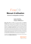
W210A WDAS Wireless Data Acquisition and Control Device W210A User’s Guide Ver 3.0 Sebine Technology Co., Ltd. W20A_20100611.hwp W210A Content 1. Overview 1.1 Product Overview 1.2 Specifications 2. Operation Mode 2.1 PC Mode 3. Device Connection 3.1 Power Supply 3.2 Analog Input Connection and Configuration 3.3 Antenna Connection 4. Configuration Settings 4.1 Hardware Connection 4.2 Configuration Setting as per Operation Mode 5. Carrier Sensing 6. Examples Appendix 1. Plan View Appendix 2. Version Update History W20A_20100611.hwp W210A 1. Overview 1.1 Product Overview W20A, one of the WDAS (Wireless Data Acquisition and Control Device) products, wirelessly transmits analog input data acquired on the field. Using W20A, a user can set a communication channel through a configuration setting program. When shipped, such data as bandwidth, channel number and serial number are written on the product. Figure 1. W20A W20A_20100611.hwp W210A 1.1.1 Product Application Cases Figure 2. Wireless Transmission of Sensor Value through W20A and M10A 1.1.2 Product Uses Replacement with existing wired systems : Solution for difficult maintenance related to complex cable connection Conditions where cable connection is problematic : Long cables, etc Conditions where wired data gathering is troublesome : Volume monitoring on an outdoor water storage tank, etc 1.1.3 Product Application Scope Pump, pipeline, fluid monitoring system Tank level, temperature monitoring system 1.1.4 Product Components W20A mainframe, λ/4 dipole antenna 1, power connector 1, analog input connector 1 W20A_20100611.hwp W210A 1.2 Specifications Item Specification Model W20A Size 109mm(L)×69mm(W)×18.6mm(H) (Antenna excluded) Case Aluminum case Weight 150g (Antenna excluded) Power Supply +12Vdc ±10%, Embedded with circuit breaker against backward voltage, over-voltage and over-current Power 5[P$7[P$:'75HVHWP$#9GF Consumption Operation -10℃ ~ +0℃ Temperature RF Features • Frequency : 40+]a0+] • Transmitter Power : 10mW • Receiver Sensitivity : aG%PG%PW\S • Modulation : FSK • Bandwidth : <KHz Performance • Expected Line-Of-Sight Range : Up To 1.5km with λ/4 Dipole Antenna • RF Data Rate:.%DXG.%DXG I/O Interface Analog Input 2 Channel Analog Input • Data Splitting : 16 bit • Analog Input Type Jumper Setting Option : Current / Voltage • Range Selection Option through Jumper at Voltage Inputting : 0~5V, 0~10V, 4~20mA Antenna • SMA connector Interface • Impedance 50Ω Table 1. W20A Specifications W20A_20100611.hwp W210A 2. Operation Mode W20A enables a user to select PC mode or device mode in accordance with his or her needs and confines a function code and function for the selected mode. Please refer to the Programmer Guide for detailed protocol and function code. 2.1 PC Mode 2.1.1 Definition of PC Mode Data shall be transferred via a serial port at a designated function protocol and then transmitted. Figure 3. W20A in PC Mode 2.1.2 Function Codes used in PC mode - READ : Instructs WDAS device to read status of DI[Digital Input] and AI[Analog Input] - READ_RESPONSE : Used when WDAS device receives READ function code and transmits current input status 2.1.3 Configuration Items to be set prior to Use of PC Mode - Selection of PC mode at PC/device mode setting W20A_20100611.hwp W210A 2.2 Device Mode 2.2.1 Definition of Device Mode If you set a device installed with usable serial port for PC mode or device mode as destination and input data to the serial port at once, then the data shall be automatically transmitted. Figure 4. W20A in Device Mode 2.2.2 Function Codes used in Device Mode - DEVICE_READ : Receives data of DI[Digital Input] and AI[Analog Input] from WDAS in device mode and outputs the data to a serial port 2.2.3 Configuration Items to be set prior to Use of Device Mode - Selection of device mode at PC/device mode setting - Selection of destination ID at destination ID setting W20A_20100611.hwp W210A 3. Device Connection Figure 5. Exterior of W20A W20A_20100611.hwp Figure 6. Interior of W20A W210A 3.1 Power Supply W20A operates at +12Vdc and is embedded with a circuit breaker against backward voltage, over-voltage and over-current. Power is supplied through power connector as depicted in the figures below. W20A does not have a separate power switch so that it will be in operation mode soon after power is supplied through power connector. Power supply indicator LED will twinkle when power supply is normal. ① As depicted in Figure 7, peel off sheath of cable about 7mm, place it on the socket and fasten upper screw. ② Connect to the power supply as depicted in Figure 8. ③ Connect the socket to W210A’s power unit as described in Figure 9. Figure 7. Power Supply-1 W20A_20100611.hwp Figure 8. Power Supply-2 Figure 9. Power Supply-3 W210A 3.2 Analog Input Connection and Configuration W20A is compatible with 2 channel analog input. To use analog input function, analog input connector shown in Figure 10 shall be used. Analog input connector shall be included in the product package, and its connection is same as that of power supply connector. Figure 10. W20A Analog Input Connector 3.2.1 Analog Input Connection Analog input channel is measured by the difference between AGND and relevant analog input channel pins. Therefore, each side of a device for analog inputting is connected to relevant channel pins and AGND, respectively. 3.2.2 Analog Input Channel Setting In order to use analog input, it is required for AI#0 voltage input level setting jumper, AI#1 voltage input level setting jumper, AI#0 voltage/current input setting jumper and AI#1 voltage/current input setting jumper to be set. W20A_20100611.hwp W210A Figure 11. W20A Analog Input Channel Setting Diagram AI#0 : AI#0 is capable of selecting voltage or current input. For voltage input, set J8 jumper at V, use J6 jumper for voltage input range setting, and input voltage through analog input connector’s #1 pin. For current input, set J8 jumper at C and input current through analog input connector’s #4 pin. AI#1 : AI#1 is capable of selecting voltage or current input. For voltage input, set J9 jumper at V, use J7 jumper for voltage input range setting, and input voltage through analog input connector’s #2 pin. For current input, set J9 jumper at C and input current through analog input connector’s #5 pin. W20A_20100611.hwp W210A 3.3 Antenna Connection Connect SMA-J(Female) connector attached to W20A to SMA-P(Male) connector antenna. Default antenna is λ/4 Dipole Antenna. Figure 12. SMA-J Antenna Connector W20A_20100611.hwp W210A 4. Configuration Settings Configuration settings for device shall be implemented through SetModemEnv.exe program. Refer to the corresponding manual for details. 4.1 Hardware Connection Use DBG port in Figure 13 for PC connection. Figure 13. Hardware Connection-1(W20A) Figure 14. Hardware Connection-2(PC) For communication frequency setting, the port in Figure 13 and PC should be connected through serial communication program. Figure 15. Hardware Connection-3 Hardware connection between W20A and PC shall be completed as depicted in Figure 15. W20A_20100611.hwp W210A 4.2 Configuration Setting as per Operation Mode 4.2.1 PC Mode - PC/DEVICE MODE Setting : PC MODE Setting - Channel Setting : Communication Frequency Setting - Tx Power Level Setting : Communication Output Level Setting - UART Configuration : Selection of RS232/RS485 & Setting of Data Bit, Parity Bit, Stop Bit 4.2.2 Device Mode - PC/DEVICE MODE Setting : DEVICE MODE Setting - Channel Setting : Communication Frequency Setting - Tx Power Level Setting : Communication Output Level Setting - DESTINATION ID Setting : DESTINATION ID Setting - UART Configuration : Selection of RS232/RS485 & Setting of Data Bit, Parity Bit, Stop Bit 4.2.3 Configuration Setting Program 1) PC/Device Mode Setting (Mode Setting) Figure 16. Configuration Setting Program – Mode Setting W20A_20100611.hwp W210A 2) Channel Setting (Communication Frequency Setting) Figure 17. Configuration Setting Program – Channel Setting 3) Tx Power Level Setting (Communication Output Level Setting) Figure 18. Configuration Setting Program – Tx Power Level Setting W20A_20100611.hwp W210A 4) DESTINATION ID Setting Figure 19. Configuration Setting Program – DESTINATION ID Setting 5) Period Setting (Transmission Cycle Setting) Figure 20. Configuration Setting Program – Period Setting W20A_20100611.hwp W210A 5. Carrier Sensing To avoid a collision with other RF systems using the same communication channel, W20A attains Received Signal Strength Indication (RSSI) prior to RF transmission and checks if there is a carrier in the channel. Standard for RSSI prescribed in the Radio Wave Laws and Regulation is 2uV, which is equivalent to -101dBm if converted into dBm. If RSSI > 2uV, then W20A shall not transmit any data through RF communication. W20A_20100611.hwp W210A 6. Examples (Example 1) Communication between W20A (PC MODE/DEVICE MODE) and M10A (PC MODE) Figure 21. Communication between W20A & M10A (Example 2) Communication between W20A (DEVICE MODE) and W50A (PC MODE) Figure 22. Communication between W20A & W50A W20A_20100611.hwp W210A Appendix 1. Plan View Front Bottom W20A_20100611.hwp Right W210A Appendix 2. Version Update History Version H/W Version Date Changes 1.0 RF1-AE-AI Ver1.2 02/23/2010 Initial Release Version 2.0 RF1-AE-AI Ver1.2 06/14/2010 Modified W210A_20100611.hwp W210A Sebine Technology Co., Ltd. Homepage : http://www.sebinetech.com E-mail : [email protected] Room #202, Daedeok Radio Engineering Center, 694, Tamnip-dong, Yuseonggu, Daejeon, Korea 305-510 Tel : 82-42-935-2084, 2085 Fax : 82-42-935-2088 W210A_20100611.hwp