1
MEA
3.1
Mesh Sensor Monitor
Users Guide
Document Revision 3.1.3
Mesh Enabled Architecture
Mesh Sensor Monitor
Copyrights
The Motorola products described in this document may include copyrighted Motorola computer programs. Laws in the
United States and other countries reserve for Motorola certain exclusive rights for copyrighted computer programs.
Accordingly, any copyrighted Motorola computer programs contained in the Motorola products described in this
document may not be copied or reproduced in any manner without the express written permission of Motorola.
Furthermore, the purchase of Motorola products shall not be deemed to grant either directly or by implication,
estoppels or otherwise, any license under the copyrights, patents or patent applications of Motorola, except for the
normal nonexclusive, royalty-free license to use that arises by operation of law in the sale of a product.
Disclaimer
Please note that certain features, facilities and capabilities described in this document may not be applicable to or
licensed for use on a particular system, or may be dependent upon the characteristics of a particular mobile
subscriber unit or configuration of certain parameters. Please refer to your Motorola contact for further information.
Trademarks
Motorola, the Motorola logo, and all other trademarks identified as such herein are trademarks of Motorola, Inc. All
other product or service names are the property of their respective owners.
Copyrights
© 2005 Motorola, Inc. All rights reserved. No part of this document may be reproduced, transmitted, stored in a
retrieval system, or translated into any language or computer language, in any form or by any means, without the
prior written permission of Motorola, Inc.
i
Mesh Enabled Architecture
Mesh Sensor Monitor
Table of Contents
OVERVIEW................................................................................................................................... 1
SUPPORTED OPERATING SYSTEMS ....................................................................................... 1
SYSTEM REQUIREMENTS ......................................................................................................... 1
INSTALLING MESH SENSOR MONITOR ................................................................................... 2
OPERATION................................................................................................................................. 5
Mesh Sensor Monitor Main Window .................................................................................. 5
Sensor ID Window ............................................................................................................... 6
Alert Window ........................................................................................................................ 7
Activity Window ................................................................................................................... 8
Node Data Summary Pane ............................................................................................... 9
Current Incoming Activity Window .................................................................................... 9
File Menu Options.............................................................................................................. 11
Open ............................................................................................................................... 11
Save As........................................................................................................................... 11
Workspace Configuration................................................................................................ 12
Open Workspace ............................................................................................................ 13
Save Workspace ............................................................................................................. 13
Close Workspace ............................................................................................................ 13
Recent Workspaces ........................................................................................................ 13
View Menu Options............................................................................................................ 14
Log Entries ...................................................................................................................... 14
Sensor Templates View Window ...................................................................................... 16
Sensor Template............................................................................................................. 17
ii
Mesh Enabled Architecture
Mesh Sensor Monitor
Tools Menu Option ............................................................................................................ 20
Toolbars Tab ................................................................................................................... 21
Button Icon ......................................................................................................................... 21
Command Tab ................................................................................................................ 23
Window Menu Options ...................................................................................................... 24
Help Menu Options ............................................................................................................ 24
CUSTOMER SERVICE INFORMATION .................................................................................... 25
Obtaining Support ............................................................................................................. 25
System Information ........................................................................................................... 25
Return Material Request.................................................................................................... 26
Radio Products and Services Division ............................................................................ 26
Radio Products and Services Division Telephone Numbers........................................... 26
Returning System Components to Motorola................................................................... 26
Returning FREs.................................................................................................................. 26
PRODUCT WARRANTY INFORMATION .................................................................................... 1
APPENDIX A ................................................................................................................................ 4
iii
Mesh Enabled Architecture
Mesh Sensor Monitor
List of Figures
Figure 1.
MeshSensor Systems Setup – Initial Installation Dialog .....................................2
Figure 2.
MeshSensor Systems Setup – License Agreement Dialog .................................2
Figure 3.
Ready to Install Dialog............................................................................................3
Figure 4.
Mesh Sensor Monitor Notice Dialog......................................................................3
Figure 5.
Performing Setup Actions Dialog ..........................................................................4
Figure 6.
MeshSensor Systems Installed Successfully Dialog...........................................4
Figure 7.
Mesh Sensor Monitor GUI ......................................................................................5
Figure 8.
Sensor ID Window...................................................................................................6
Figure 9.
Alert Window ...........................................................................................................7
Figure 10.
Sensor Activity Window .....................................................................................8
Figure 11.
Node Data Summary Pane..................................................................................9
Figure 12.
Current Incoming Activity Window....................................................................9
Figure 13.
Windows File Open Dialog ...............................................................................11
Figure 14.
Windows File Save As Dialog..........................................................................11
Figure 15.
An Example of Workspace Configuration.......................................................12
Figure 16.
Open Workspace Dialog ...................................................................................13
Figure 17.
Log Entries Window ..........................................................................................14
Figure 18.
Sensor Templates View Window......................................................................16
Figure 19.
Sensor Template Display Properties Dialog ...................................................17
Figure 20.
User Defined Data Columns Dialog .................................................................19
Figure 21.
Tools Customize Dialog Toolbars Tab ............................................................20
Figure 22.
New Toolbar Dialog ...........................................................................................21
Figure 23.
Large Button Display Option............................................................................21
Figure 24.
Tools Customize Dialog Command Tab..........................................................23
iv
Mesh Enabled Architecture
Geo-Location Reference Guide
Overview
The Mesh Sensor Monitor (MSM) application provides an interface that allows a user/operator
to send or receive data from a remote wireless sensor node within a Mesh Enabled Architecture
(MEA™) network. Sensor devices can be connected to the MEA wireless device via an RS-232
or an RS-485 interface. Mesh Sensor Monitor is designed as a debug tool for sensor network
development, sensor/network integration, or third party development of sensor management
applications. A Mesh Sensor API is available for third party development of custom sensor
management applications.
Although MSM is used as the means for communicating directly with remote sensor devices, the
MeshManager™ suite of Element Management software applications must be used to configure
the serial interface on the MEA hardware (MWR6300/WSM6300). Configurable parameters
include baud rate, packetization parameters (time interval, sync character, number of
characters), GPIO configuration (input/output) and server IP address (the IP address of the host
executing the MSM application).
Supported Operating Systems
•
Microsoft Windows 2000
•
Microsoft Windows XP
System Requirements
1
•
Motorola Device Manager version 9.x.x or higher
•
Mobile Wireless Router (MWR6300) / Mesh Sensor Monitor (MSM6300)
Mesh Enabled Architecture
Mesh Sensor Monitor
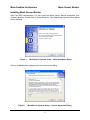
Installing Mesh Sensor Monitor
Insert the MEA Administration CD and install the Mesh Sensor Monitor application from
/Software directory. Double click on SensorSetup.exe. The MeshSensor Systems Setup dialog
will be displayed.
Figure 1.
MeshSensor Systems Setup – Initial Installation Dialog
Click on the Next button to display the License Agreement dialog.
Figure 2.
MeshSensor Systems Setup – License Agreement Dialog
2
Mesh Enabled Architecture
Geo-Location Reference Guide
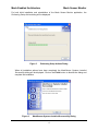
After reading the License Agreement, select the YES radio button and click on the Next button
to continue. When the Ready to Install dialog is displayed, confirm the default Install and
Shortcut folders and click on the Next button to proceed with the installation.
Figure 3.
Ready to Install Dialog
If you have previously installed the Mesh Sensor Monitor application, the Notice dialog will be
displayed. Click on the Yes button to confirm you wish to overwrite the existing MSM.mdb file.
Figure 4.
3
Mesh Sensor Monitor Notice Dialog
Mesh Enabled Architecture
Mesh Sensor Monitor
For both initial installation and reinstallation of the Mesh Sensor Monitor application, the
Performing Setup Actions dialog will be displayed.
Figure 5.
Performing Setup Actions Dialog
When all installation actions have been completed, the MeshSensor Systems Installed
Successfully dialog will be displayed. Click on the Finish button to dismiss the dialog and
complete the installation.
Figure 6.
MeshSensor Systems Installed Successfully Dialog
4
Mesh Enabled Architecture
Geo-Location Reference Guide
Operation
All functional operations for the MSM are performed using the Mesh Sensor Monitor Graphical
User Interface (GUI).
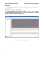
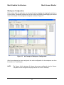
Mesh Sensor Monitor Main Window
The Mesh Sensor Monitor (MSM) main window is shown in Figure 7.. This is the display
configuration presented at application startup. This configuration presents four sub-windows,
which are described in detail in the following sections.
Figure 7.
5
Mesh Sensor Monitor GUI
Mesh Enabled Architecture
Mesh Sensor Monitor
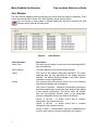
Sensor ID Window
The Sensor ID Window displayed on the Sensors tab shows a list of all sensors that have been
discovered. Only active sensors are available to the user for communication. Active sensors are
designated by a blinking green indicator displayed to the left of the corresponding MAC address.
Devices can be sorted or identified by MAC address, IP address, name, or activity. To manage
the device display attributes, right click on the device ID.
By default, any new sensor will initially be filed in the Unconfigured Sensors folder until
additional configuration parameters are applied.
Figure 8.
Sensor ID Window
6
Mesh Enabled Architecture
Geo-Location Reference Guide
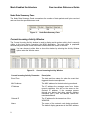
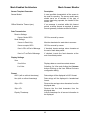
Alert Window
The Alert Window displays certain events that may occur while the system is operating. These
events are summarized by Event Time, MAC Address, Name, and the Status.
You can choose to either enable or disable display this window by selecting the Alert
Window option under the Window menu.
Figure 9.
Alert Window
Alert Parameter
Description
Event Time
The date and time stamp for when the event that triggered the
alert was captured.
MAC Address
The MAC address for the device being monitored.
Name
The name of the network node being monitored. The name
displayed here will vary depending on the display attributes
selected. The default display parameter is the MAC address
formatted to remove hyphenation.
Status
The current status of the sensor device. One of the following
Alert Status messages will be displayed:
New Sensor Detected – Additional configuration parameters
have been applied and a sensor has been detected and added
to the network configuration. The device name will migrate
from the Unconfigured Sensors folder to the appropriate
network configuration folder in the Sensor ID Window.
Sensor is On-Line – A sensor device that is currently
configured in the network is on-line.
Sensor is Off-Line – A sensor device that is currently
configured in the network is off-line.
Sensor is Dead – Communications cannot be established with
a sensor device that is currently configured in the network.
7
Mesh Enabled Architecture
Alert Parameter
Mesh Sensor Monitor
Description
Sensor is Resurrected – Communications have been restored
for a sensor device that is currently configured in the network
that was formerly unreachable.
Activity Window
The Activity Window displays message information, such as date and time, direction, sequence
#, message size, and message data (text & hex) for the selected sensor.
Figure 10.
Sensor Activity Window
Activity Parameter
Description
Data Style
Using the radio buttons on the Data Style panel directly below the
Activity Window, data to be transmitted to a sensor can be formatted
to be relayed either As Text or As Hex. Text (character based), Hex,
or a combination of Text and Hexidecimal messages can be sent to a
sensor node.
Message
The data string to be transmitted to a sensor is entered in the
Message field. The actual transfer of the data is initialized by clicking
on the Send button.
GPIO
The General Purpose I/O (GPIO) pin can be configured for input,
output, or transmit enable (RS-485 applications only) via
MeshManager. The GPIO radio buttons for Off, On, and Don’t
Change. The Insert button is used to insert unprintable characters
into a normal test message. See Appendix A for the ASCII character
set.
As depicted at the bottom left of Figure 10, multiple Sensor Activity windows can be displayed
simultaneously. Each window displayed will be identified by displaying a unique MAC address
on the window tab for easy identification.
8
Mesh Enabled Architecture
Geo-Location Reference Guide
Node Data Summary Pane
The Node Data Summary Panel summarizes the number of data packets and bytes received
and sent from the specified sensor node.
Figure 11.
Node Data Summary Pane
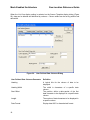
Current Incoming Activity Window
The Current Incoming Activity window is used to display serial modem activity that is currently
visible to the host device executing the MSM application. The node table is populated
automatically after active nodes have been selected from the Sensor ID window.
You can choose to either hide or show this window by selecting the Activity Window
option under the Window menu.
Figure 12.
Current Incoming Activity Window
Current Incoming Activity Parameter
Description
Event Time
The date and time stamp for when the event that
triggered the alert was captured.
MAC Address
The MAC address for the device being monitored.
IP Address
The IP address the message came from. Under
normal conditions, this will be the same as the
Claimed IP address. If the message passes
through any device that does network address
translation (NAT), then this address reflects the
translated address.
Claimed IP
The IP address for the transceiver of the
WSM6300.
Name
The name of the network node being monitored.
The default display parameter is the MAC address
9
Mesh Enabled Architecture
Current Incoming Activity Parameter
Mesh Sensor Monitor
Description
formatted to remove hyphenation.
The default name can be changed using the
sensor properties.
Direction
Messages being transmitted are identified as
Outbound or Inbound.
Msg Type
Messages will be categorized by the following
types:
Message Type #
Displayed Text
350
Serial Data
351
GPIO Status
352
Serial + GPIO
353
Serial + GPIO
354
Hello
Any Other
Unknown: nnn (where nnn
is the message type # that
was received)
Sequence
An increasing number that is created at the
transceiver. The first message begins with zero
and every new message increments by one.
Size
The size of the message in bytes. The actual
number of bytes that came in the payload from the
sensor. It does not include additional bytes added
by the transceiver for header information.
Message
Message content displayed in a printable text
format. Any nonprintable character in the message
will be displayed as a period.
10
Mesh Enabled Architecture
Geo-Location Reference Guide
File Menu Options
The MSM makes use of several file types. The *.msm file format is used to store sensor data
communications activity. The *.smw file format is used to store a specific workspace
configuration for future access.
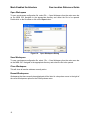
Open
To open a sensor data capture file, select File → Open from the main menu bar on the MSM
GUI: Navigate to the appropriate directory and select the file to be opened.
Figure 13.
Windows File Open Dialog
Save As
To save a sensor data capture file, select File → Save from the main menu bar on the MSM
GUI This will display the Windows Save As dialog. Navigate to the appropriate directory and
select an existing file specify a new file name or to be overwritten.
Figure 14.
11
Windows File Save As Dialog
Mesh Enabled Architecture
Mesh Sensor Monitor
Workspace Configuration
Each window within the application can be repositioned by dragging and dropping the window to
a new location. Workspace windows can also be resized by selecting and dragging the desired
corner. An example of a reconfigured workspace is shown in Figure 15.
Figure 15.
An Example of Workspace Configuration
After the workspace has been configured, the entire configuration for the workspace can then
be saved as a *.smw file type.
NOTE:
The Sensor Activity windows (4) shown above were configured using the Sensor
Template and are configured to display data as ASCII with Timestamp.
12
Mesh Enabled Architecture
Geo-Location Reference Guide
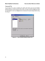
Open Workspace
To open a workspace configuration file, select File → Open Workspace from the main menu bar
on the MSM GUI. Navigate to the appropriate directory and select the file to be opened.
Double click on the file name or click on the Open button.
Figure 16.
Open Workspace Dialog
Save Workspace
To save a workspace configuration file, select File → Save Workspace from the main menu bar
on the MSM GUI. Navigate to the appropriate directory and select the file to be opened.
Close Workspace
This will close all monitor windows currently active.
Recent Workspaces
Workspaces that have recently been displayed will be listed in a drop-down menu to the right of
the recent Workspaces option on the File drop-down menu.
13
Mesh Enabled Architecture
Mesh Sensor Monitor
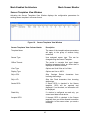
View Menu Options
In addition to options for viewing different windows and toolbars, the View menu allows you to
modify the parameters on the Display (Sensor) Template.
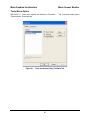
Log Entries
The Log Entries Window displays the following information for all current log entries.
Figure 17.
Log Entries Window
Log Entry Data Type
Description
Entry ID
A sequence number assigned by the system indicating the
order in which the log entry was made.
Time
Time stamp for when the message was received.
Direction
Indicates whether the message was received (Inbound) or
sent (Outbound).
MAC
MAC address for the device being monitored.
Source IP
Source IP address for the device being monitored.
Claimed IP
The IP address for the transceiver of the WSM6300.
14
Mesh Enabled Architecture
Geo-Location Reference Guide
Log Entry Data Type
Description
Msg Type
Messages will be categorized by the following types:
Message Type #
Displayed Text
350
Serial Data
351
GPIO Status
352
Serial + GPIO
353
Serial + GPIO
354
Hello
Any Other
Unknown: nnn (where nnn
is the message type # that
was received)
Sequence
An increasing number that is created at the transceiver. The
first message begins with zero and every new message
increments by one.
Size
The size of the message in bytes. The actual number of
bytes that came in the payload from the sensor. It does not
include additional bytes added by the transceiver for header
information.
Message
Message content displayed in a printable text format. Any
nonprintable character in the message will be displayed as
a period.
15
Mesh Enabled Architecture
Mesh Sensor Monitor
Sensor Templates View Window
Activating the Sensor Templates View Window displays the configuration parameters for
existing sensor template in columnar format.
Figure 18.
Sensor Templates View Window
Sensor Templates View Column Header
Description
Template Name
The name of the template whose parameters
will apply to the group of sensors being
monitored.
Sensor Type
User assigned sensor type. This can be
changed using the Sensor Template.
Offline Timeout
The period in seconds that must elapse
between messages before an offline alert is
displayed in the Alert window.
View Type
Options are Scroll View or List View.
Display Type
Options are Hex or ASCII.
Strip <CR>
Strip Carriage Return
incoming data strings.
Strip <LF>
Strip Line Feed characters from incoming
data strings.
Sends GPIO
If Sends GPIO is checked in the Sensor
template, GPIO will be reported and
displayed. If not checked, no information will
be displayed.
Read Only
If a device is configured as read only, you
cannot send data to that device.
Accepts GPIO
If Accepts GPIO is checked in the Sensor
template, then you will be allowed to send the
information to the sensor when you send a
message.
16
characters
from
Mesh Enabled Architecture
Geo-Location Reference Guide
Sensor Templates View Column Header
Description
Send <CR>
Send Carriage Return characters in outbound
data strings.
Send <LF>
Send Line Feed characters in outbound data
strings.
Display Timestamp
Display the timestamp.
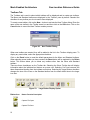
Sensor Template
Each sensor in the Sensor ID Window can be uniquely configured using a sensor template. The
template is accessed by double-clicking on the Sensor ID displayed in the Sensor ID Window.
The Sensor Template display properties window is shown in Figure 19.
Figure 19.
Sensor Template Display Properties Dialog
This template is used to configure many of the parameters used to transmit data to a specific
sensor.
Sensor Template Parameter
Description
Template Name:
Existing or new name to be applied to the
unique template developed for each sensor.
17
Mesh Enabled Architecture
Mesh Sensor Monitor
Sensor Template Parameter
Description
Sensor Model:
A user specified characteristic of the sensor to
be used for reporting. The sensor model name
should serve as a reminder of the type of
sensor data being reported, the location of the
sensor, etc.
Offline Detection Timeout (sec):
If no message is received within this timeout
period, a sensor timeout is reported. A sensor
timeout generally indicates a radio link failure.
Data Transmission:
Receive Settings:
Sensor Sends GPIO
GPIO is sourced by sensor.
Send Settings:
Sensor is Read-Only
Must be deselected to send data to a sensor.
Sensor accepts GPIO
GPIO is sourced by sensor.
Send <CR> at End-of-Message
If checked, inserts carriage return character at
the end of each data packet.
Send <LF> at End-of-Message
If checked, inserts line feed character at the
end of each data packet.
Display Settings:
View
Scroll View
Displays data as a continuous data stream.
List View
Selecting List View and clicking the Columns
button will bring up the User Defined Columns
configuration dialog.
Format
ASCII (with or without timestamp)
Data strings will be displayed in ASCII format.
Hex (with or without timestamp)
Data strings will be displayed in hexadecimal
format.
Strip <CR>
Remove the carriage return characters from the
displayed data.
Strip <LF>
Remove the line feed characters from the
displayed data.
Display Timestamp
Include timestamp for all sensor information to
be displayed.
18
Mesh Enabled Architecture
Geo-Location Reference Guide
When the List View display setting is selected on the Sensor Template display dialog (Figure
20), data can be labeled and delimited by columns. Column widths can be set by position and
data width.
Figure 20.
User Defined Data Columns Dialog
User Defined Data Columns Parameter
Definition
Heading
A logical title for the column of data to be
displayed.
Heading Width
The width in characters of a specific data
column.
Start Offset
The position, within a data packet, of the first
data character to be displayed in a specific data
column.
Length
The number of data characters to be displayed in
a specific column.
Data Format
Display data ASCII or hexadecimal format.
19
Mesh Enabled Architecture
Mesh Sensor Monitor
Tools Menu Option
With MEA 3.1, Tools menu options are limited to Customize… . The Customize dialog has a
Toolbars and a Command tab.
Figure 21.
Tools Customize Dialog Toolbars Tab
20
Mesh Enabled Architecture
Geo-Location Reference Guide
Toolbars Tab
The Toolbars tab is used to select which toolbars will be displayed and to create new toolbars.
The Menu and Standard toolbars are displayed in the Toolbars: pane by default. Deselect the
checkbox for any toolbar you do not want to have displayed.
To create a new toolbar, click on the New… button to activate the New Toolbar dialog. Enter the
name of the new toolbar in the Toolbar name: box and then click on the OK button. Click on the
Cancel button to cancel the New Toolbar creation process.
Figure 22.
New Toolbar Dialog
When new toolbars are created, they will be added to the list in the Toolbars: display pane. To
display any new toolbar, select the appropriate checkbox.
Click on the Reset button to reset the default parameters for the Menu and Standard toolbars.
When selecting a new toolbar you have created, the Reset button will be replaced by the Delete
button. This button allows you to delete any toolbars other than the Menu and Standard
toolbars.
There are three checkboxes on the Toolbar tab. Selecting the Show Tooltips box will display
information about the individual tool buttons on mouse over. Selecting Cool Look removes the
three-dimensional shading from the toolbars and buttons. Selecting the Large Buttons checkbox
changes the size of the icons on the Standard toolbar from the small default size to the larger
icon size.
Figure 23.
Button Icon
Button Function Description
Capture File Open
Capture File Save
21
Large Button Display Option
Mesh Enabled Architecture
Mesh Sensor Monitor
Display Template Properties
Change Font used for displaying sensor data
Enable or Disable Auto-Scroll in a Sensor Activity Window (only available in List View) Disables automatic scrolling of new messages in window
Clear messages in selected Sensor Activity Window
Select Scroll View display for active Sensor Activity Window
Select List View display for active Sensor Activity Window
Enable or Disable display of Alert Window
Enable or Disable display of Current Activity window
Display the About box
For a more convenient display configuration, application subwindows may be configured to float
on the desktop.
22
Mesh Enabled Architecture
Geo-Location Reference Guide
Command Tab
The Command tab is used to populate new toolbars with button icons from the Standard
(default) toolbar or selections from the Menu toolbar. Click on the desired selection and drag
and drop the button or menu selection item onto the new toolbar. Click on the OK button when
you are finished or click on the Cancel button to dismiss the Customize dialog without saving
the changes.
Figure 24.
23
Tools Customize Dialog Command Tab
Mesh Enabled Architecture
Mesh Sensor Monitor
Window Menu Options
The Windows menu allows you to activate or deactivate the display of the Activity and Alert
windows on the MSM GUI.
Help Menu Options
With MEA 3.1, the only Help option available is the About Mesh Sensor Monitor information
panel.
24
Mesh Enabled Architecture
Geo-Location Reference Guide
Customer Service Information
If you have read this document and made every effort to resolve installation or operation issues
yourself and still require help, please contact Motorola System Support Center (SSC) using the
following contact information:
Hours of Operation
7 days a week, 24 hours
Technical Support:
800-221-7144 (USA)
Obtaining Support
Motorola provides technical support services for your system and recommends that you
coordinate warranty and repair activities through the Motorola System Support Center (SSC).
When you consult the Motorola SSC, you increase the likelihood that problems are rectified in a
timely fashion and that warranty requirements are satisfied. Check your contract for specific
warranty and service information.
System Information
To be provided with the best possible opportunity for support, collect the following system
information and have it available when obtaining support.
•
Location of the system
•
Date the system was put into service
•
Software or firmware version information for components of your system
•
Serial number(s) of the device(s) or component(s) requiring support
•
A written description of the symptom or observation of the problem:
- When did it first appear?
- Can it be reproduced?
- What is the step-by-step procedure to cause it?
•
Do other circumstances contribute to the problem? For example, changes in weather or
other conditions?
•
Maintenance action preceding problem:
- Upgrade of software or equipment
- Change in the hardware or software configuration
- Software reload - from backup or from CD-ROM (note the version and date)
25
Mesh Enabled Architecture
Mesh Sensor Monitor
Return Material Request
After collecting system information, contact the Motorola System Support Center for assistance
or to obtain a Return Material Authorization (RMA) number for faulty Field Replaceable Entities
(FREs):
North America: 800-221-7144
Radio Products and Services Division
The Radio Products and Services Division is your source for manuals and replacement parts.
Radio Products and Services Division Telephone Numbers
The telephone numbers for ordering are: (800)-422-4210 (US and Canada orders)
The Fax numbers are: (800)-622–6210 (US and Canada orders)
The number for help identifying an item or part number is (800)-422-4210; select choice “3”
from the menu
Returning System Components to Motorola
Motorola's service philosophy is based on field replaceable entities (FREs). FREs are system
components identified by Motorola to be returned to Motorola for repair. In turn, Motorola sends
you a replacement FRE component to help you maintain maximum operating performance for
your system.
Returning FREs
Return faulty FREs to Motorola for repair. When you return an assembly for service, follow
these best practices:
•
Place any assembly containing CMOS devices in a static-proof bag or container for
shipment.
•
Obtain a return authorization (RA) number from the Motorola System Support Center.
•
Include the warranty, model, kit numbers, and serial numbers on the job ticket, as
necessary.
•
If the warranty is out of date, you must have a purchase order.
•
Print the return address clearly, in block letters.
•
Provide a phone number where your repair technician can be reached.
•
Include the contact person's name for return.
•
Pack this assembly tightly and securely, preferably in its original shipping container.
26
Mesh Enabled Architecture
Geo-Location Reference Guide
Product Warranty Information
This warranty applies within the fifty (50) United States, the District of Columbia and Canada.
LIMITED WARRANTY
MOTOROLA COMMUNICATION PRODUCTS
If the affected product is being purchased pursuant to a written Communications System
Agreement signed by Motorola, the warranty contained in that written agreement will apply.
Otherwise, the following warranty applies.
I. WHAT THIS WARRANTY COVERS AND FOR HOW LONG:
Motorola Inc. or, if applicable, Motorola Canada Limited ("Motorola") warrants the Motorola
manufactured Broadband Data communications product, against material defects in material and
workmanship under normal use and service for a period of One (1) Year from the date of
shipment.
Motorola, at its option, will at no charge either repair the Product (with new or reconditioned
parts), replace it with the same or equivalent Product (using new or reconditioned Product), or
refund the purchase price of the Product during the warranty period provided purchaser notifies
Motorola according to the terms of this warranty. Repaired or replaced Product is warranted for
the balance of the original applicable warranty period. All replaced parts of the Product shall
become the property of Motorola.
This express limited warranty is extended by Motorola to the original end user purchaser
purchasing the Product for purposes of leasing or for commercial, industrial, or governmental use
only, and is not assignable or transferable to any other party. This is the complete warranty for the
Product manufactured by Motorola. Motorola assumes no obligations or liability for additions or
modifications to this warranty unless made in writing and signed by an officer of Motorola. Unless
made in a separate written agreement between Motorola and the original end user purchaser,
Motorola does not warrant the installation, maintenance or service of the Product.
Motorola cannot be responsible in any way for any ancillary equipment not furnished by Motorola
which is attached to or used in connection with the Product, or for operation of the Product with
any ancillary equipment, and all such equipment is expressly excluded from this warranty.
Because each system which may use the Product is unique, Motorola disclaims liability for range,
coverage, or operation of the system as a whole under this warranty.
II. GENERAL PROVISIONS:
This warranty sets forth the full extent of Motorola's responsibilities regarding the Product.
Repair, replacement or refund of the purchase price, at Motorola's option, is the exclusive remedy.
THIS WARRANTY IS GIVEN IN LIEU OF ALL OTHER EXPRESS WARRANTIES. MOTOROLA
DISCLAIMS ALL OTHER WARRANTIES OR CONDITIONS, EXPRESS OR IMPLIED, INCLUDING THE
IMPLIED WARRANTIES OR CONDITIONS OF MERCHANTABILITY AND FITNESS FOR A
PARTICULAR PURPOSE. IN NO EVENT SHALL MOTOROLA BE LIABLE FOR DAMAGES IN
EXCESS OF THE PURCHASE PRICE OF THE PRODUCT, FOR ANY LOSS OF USE, LOSS OF TIME,
INCONVENIENCE, COMMERCIAL LOSS, LOST PROFITS OR SAVINGS OR OTHER INCIDENTAL,
SPECIAL, INDIRECT OR CONSEQUENTIAL DAMAGES ARISING OUT OF THE USE OR INABILITY
TO USE SUCH PRODUCT, TO THE FULL EXTENT SUCH MAY BE DISCLAIMED BY LAW.
III. HOW TO GET WARRANTY SERVICE:
Purchaser must notify Motorola's representative or call Motorola's Customer Response Center at
1-800-247-2346 within the applicable warranty period for information regarding warranty service.
IV. WHAT THIS WARRANTY DOES NOT COVER:
1
Mesh Enabled Architecture
Mesh Sensor Monitor
A) Defects or damage resulting from use of the Product in other than its normal and customary
manner.
B) Defects or damage from misuse, accident, water, or neglect.
C) Defects or damage from improper testing, operation, maintenance, installation, alteration,
modification, or adjustment.
D) Breakage or damage to antennas unless caused directly by defects in material workmanship.
E) A Product subjected to unauthorized Product modifications, disassemblies or repairs
(including, without limitation, the addition to the Product of non-Motorola supplied equipment)
which adversely affect performance of the Product or interfere with Motorola's normal warranty
inspection and testing of the Product to verify any warranty claim.
F) Product which has had the serial number removed or made illegible.
G) Batteries (they carry their own separate limited warranty).
H) Freight costs to the repair depot.
I) A Product which, due to illegal or unauthorized alteration of the software/firmware in the
Product, does not function in accordance with Motorola's published specifications or with the
FCC type acceptance labeling in effect for the Product at the time the Product was initially
distributed from Motorola.
J) Scratches or other cosmetic damage to Product surfaces that does not affect the operation of
the Product.
K) That the software in the Product will meet the purchaser's requirements or that the operation
of the software will be uninterrupted or error-free.
L) Normal and customary wear and tear.
M) Non-Motorola manufactured equipment unless bearing a Motorola Part
Number in the form of an alpha numeric number (i.e., TDE6030B).
N) Lift trucks for installation, removal, replacement or repair of the Motorola supplied products
from light, power, telephone poles etc.
O) Dispatch to remote site locations
P) Loading of software upgrades or fixes into the devices.
V. GOVERNING LAW
In the case of a Product sold in the United States and Canada, this Warranty is governed by the
laws of the State of Illinois and the Province of Ontario, respectively.
VI. PATENT AND SOFTWARE PROVISIONS:
Motorola will defend, at its own expense, any suit brought against the end user purchaser to the
extent that it is based on a claim that the Product or its parts infringe a United States patent, and
Motorola will pay those costs and damages finally awarded against the end user purchaser in any
such suit which are attributable to any such claim, but such defense and payments are
conditioned on the following:
A) that Motorola will be notified promptly in writing by such purchaser of any notice of such claim;
B) that Motorola will have sole control of the defense of such suit and all negotiations for its
settlement
or
compromise;
and
C) should the Product or its parts become, or in Motorola's opinion be likely to become, the
subject of a claim of infringement of a United States patent, that such purchaser will permit
Motorola, at its option and expense, either to procure for such purchaser the right to continue
using the Product or its parts or to replace or modify the same so that it becomes non-infringing
or to grant such purchaser a credit for the Product or its parts as depreciated and accept its
return. The depreciation will be an equal amount per year over the lifetime of the Product or its
parts as established by Motorola.
2
Mesh Enabled Architecture
Geo-Location Reference Guide
Motorola will have no liability with respect to any claim of patent infringement which is based
upon the combination of the Product or its parts furnished hereunder with software, apparatus or
devices not furnished by Motorola, nor will Motorola have any liability for the use of ancillary
equipment or software not furnished by Motorola which is attached to or used in connection with
the Product. The foregoing states the entire liability of Motorola with respect to infringement of
patents by the Product or any its parts thereof.
Laws in the United States and other countries preserve for Motorola certain exclusive rights for
copyrighted Motorola software such as the exclusive rights to reproduce in copies and distribute
copies of such Motorola software. Motorola software may be used in only the Product in which the
software was originally embodied and such software in such Product may not be replaced,
copied, distributed, modified in any way, or used to produce any derivative thereof. No other use
including, without limitation, alteration, modification, reproduction, distribution, or reverse
engineering of such Motorola software or exercise of rights in such Motorola software is
permitted. No license is granted by implication, estoppel or otherwise under Motorola patent
rights or copyrights.
3
Mesh Enabled Architecture
Mesh Sensor Monitor
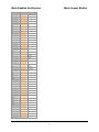
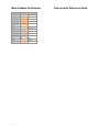
Appendix A
dec
ASCII
0
NUL
Null
1
SOH
2
STX
3
ETX
4
EOT
5
ENQ
Start of
Heading (CC)
Start of Text
(CC)
End of Text
(CC)
End of
Transmission
(CC)
Enquiry (CC)
6
ACK
7
BEL
Acknowledge
(CC)
Bell
8
BS
Backspace (FE)
9
HT
Horizontal
Tabulation (FE)
10
LF
Line Feed (FE)
11
VT
Vertical
Tabulation (FE)
12
FF
Form Feed (FE)
13
CR
14
SO
Carriage Return
(FE)
Shift Out
15
SI
Shift In
16
DLE
17
DC1
18
DC2
19
DC3
20
DC4
21
NAK
22
SYN
23
ETB
24
CAN
Data Link
Escape (CC)
Device Control
1
Device Control
2
Device Control
3
Device Control
4
Negative
Acknowledge
(CC)
Synchronous
Idle (CC)
End of
Transmission
Block (CC)
Cancel
25
EM
End of Medium
26
SUB
Substitute
27
ESC
Escape
28
FS
29
GS
30
RS
31
US
File Separator
(IS)
Group
Separator (IS)
Record
Separator (IS)
Unit Separator
(IS)
4
Mesh Enabled Architecture
dec
ASCII
32
SP
Space
33
!
34
"
Exclamation
Point
Quotation Mark
35
#
36
$
Number Sign,
Octothorp,
"pound"
Dollar Sign
37
%
Percent
38
&
Ampersand
39
'
40
(
Apostrophe,
Prime
Left Parenthesis
41
)
42
*
Right
Parenthesis
Asterisk, "star"
43
+
Plus Sign
44
,
Comma
45
-
46
.
Hyphen, Minus
Sign
Period, Decimal
Point, "dot"
47
/
48
0
0
49
1
1
50
2
2
51
3
3
52
4
4
53
5
5
54
6
6
55
7
7
56
8
8
57
9
58
:
59
;
Semicolon
60
<
Less-than Sign
61
=
Equal Sign
62
>
63
?
Greater-than
Sign
Question Mark
64
@
At Sign
65
A
A
66
B
B
67
C
C
68
D
D
69
E
E
70
F
F
71
G
G
72
H
H
5
Slash, Virgule
9
Colon
Geo-Location Reference Guide
Mesh Enabled Architecture
dec
Mesh Sensor Monitor
ASCII
73
I
I
74
J
J
75
K
K
76
L
L
77
M
M
78
N
N
79
O
O
80
P
P
81
Q
Q
82
R
R
83
S
S
84
T
T
85
U
U
86
V
V
87
W
W
88
X
X
89
Y
Y
90
Z
Z
91
[
92
\
Opening
Bracket
Reverse Slant
93
]
Closing Bracket
94
^
95
_
96
`
Circumflex,
Caret
Underline,
Underscore
Grave Accent
97
a
a
98
b
b
99
c
c
100
d
d
101
e
e
102
f
f
103
g
g
104
h
h
105
i
i
106
j
j
107
k
k
108
l
l
109
m
m
110
n
n
111
o
o
112
p
p
113
q
q
114
r
r
115
s
s
116
t
t
6
Mesh Enabled Architecture
dec
ASCII
117
u
u
118
v
v
119
w
w
120
x
x
121
y
y
122
z
z
123
{
Opening Brace
124
|
Vertical Line
125
}
Closing Brace
126
~
Tilde
127
DEL
Delete
128
7
Reserved
Geo-Location Reference Guide