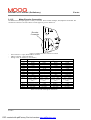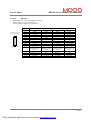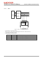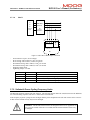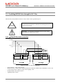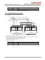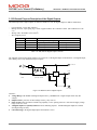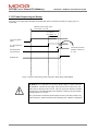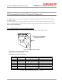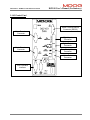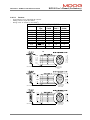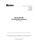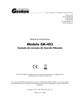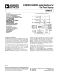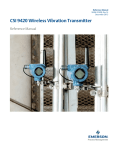
1
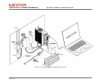
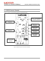
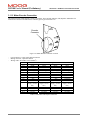
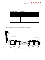
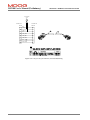
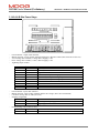
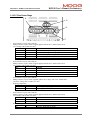
Section 3 - Wiring and Installation
DS2100
Digital Controller
PRELIMINARY
INSTALLATION
&
USER' S MANUAL
C7750-001 Rev. A 04/04
SECTION 3: WIRING AND INSTALLATION
SECTION 3:
DS2100 User's Manual (Preliminary)
WIRING AND INSTALLATION
PAGE 3-1
Errata Sheet
DS2100 User's Manual (Preliminary)
ERRATA E:
PAGE 1
PDF created with pdfFactory Pro trial version www.pdffactory.com
DS2100 User's Manual (Preliminary)
Errata
E.1 Introduction
This Errata sheet details changes to the preliminary release of the DS2100 Manual. The corrected information for the
manual is detailed below.
E.2 Changes
Page
1-5
3-54, 3-74
2-7
3-64
3-54, 3-74
Description
Update to DS2100 Boxcar
Error in Encoder connector wiring
diagram
Line fuses specified in manual for Size
C drives incorrect.
Figure 3.46 Incorrect. Lines labelled
incorrectly
Error in Encoder connector wiring
diagram
Change
Reference to Form 757 added to Boxcar for valid
ordering numbers.
Clock + & Data + Lines swapped in wiring information
Clock - & Data - Lines swapped in wiring information
Changed line fuse requirements for Size C drives from
160 FEE 690V to 100 FE 690V Bussmann Fuses.
Receive and Transmit lines re-labelled to show Receive
on DS2100 side is connected to Transmit in PC side &
Transmit on DS2100 side is connected to Receive on
PC Side.
For Heidenheim endat encoder, necessary to swap
channel A and channel B signals. Required as
Heidenheim define positive direction phasing between
A & B channels in reverse to Stegmann.
PAGE 2
PDF created with pdfFactory Pro trial version www.pdffactory.com
DS2100 User's Manual (Preliminary)
3.11.5
Errata
Motor Encoder Connection
The DS2100 encoder input supports a variety of encoders. These include Analogue, SSI, Hiperface and Endat. The
connections to the drive for each of these encoder types are given in Table 3.25.
Encoder
Connector
-
Figure 3.38 Motor Encoder Connector Location
Fixed connector: 15 pin, female Sub-D connector
Mating connector, 15pin male Sub-D
Wiring: cable. 28-18AWG (0.14-0.82mm2)
Encoder Type
Pos
Analogue
SSI
Hiperface
J4.1
J4.2
J4.3
J4.4
J4.5
J4.6
J4.7
J4.8
J4.9
J4.10
J4.11
J4.12
J4.13
J4.14
J4.15
Shield
- Sine
- Cosine
Gnd Supply
- Channel Z (Zero)
NTC/PTC
+ Sine
+ Cosine
+5 V .. +12V
Supply (150 mA
max.)
- Fault
+ Channel Z (Zero)
Gnd Supply
NTC/PTC
Shield
Gnd Supply
- Clock
- Data
NTC/PTC
+5 V .. +12V
Supply (150 mA
max.)
+ Clock
+ Data
Gnd Supply
NTC/PTC
Shield
- Sine
- Cosine
Gnd Supply
RS485 NTC/PTC
+ Sine
+ Cosine
+5 V .. +12V
Supply (150 mA
max.)
RS485 +
Gnd Supply
NTC/PTC
Table 3.25 Encoder Cable Input Connections
PAGE 4
PDF created with pdfFactory Pro trial version www.pdffactory.com
Endat
Shield
- Channel B
- Channel A
Gnd Supply
- Clock
- Data
NTC/PTC
+ Channel B
+ Channel A
+5 V .. +12V
Supply (150 mA
max.)
+ Clock
+ Data
Gnd Supply
NTC/PTC
Errata Sheet
DS2100 User's Manual (Preliminary)
3.14.5.7
Encoder
- Fixed connector: 15 pin, female Sub-D connector
- Mating connector, 15pin male Sub-D
- Wiring: cable. 28-18AWG (0.14-0.82mm2)
15-Pin Sub-D Connector
Plug (male) on cable
DS2100 Cable End
J4
Encoder Type
Hiperface
Pos
Analogue
SSI
J4.1
J4.2
J4.3
J4.4
J4.5
J4.6
J4.7
J4.8
J4.9
J4.10
J4.11
Shield
- Sine
- Cosine
Gnd Supply
- Channel Z (Zero)
NTC/PTC
+ Sine
+ Cosine
+5 V .. +12V
Supply (150 mA
max.)
- Fault
+ Channel Z (Zero)
Gnd Supply
NTC/PTC
Shield
Gnd Supply
- Clock
- Data
NTC/PTC
+5 V .. +12V
Supply (150 mA
max.)
+ Clock
+ Data
Gnd Supply
NTC/PTC
J4.12
J4.13
J4.14
J4.15
Shield
- Sine
- Cosine
Gnd Supply
RS485 NTC/PTC
+ Sine
+ Cosine
+5 V .. +12V
Supply (150 mA
max.)
RS485 +
Gnd Supply
NTC/PTC
Endat
Shield
- Channel B
- Channel A
Gnd Supply
- Clock
- Data
NTC/PTC
+ Channel B
+ Channel A
+5 V .. +12V
Supply (150 mA
max.)
+ Clock
+ Data
Gnd Supply
NTC/PTC
PAGE 5
PDF created with pdfFactory Pro trial version www.pdffactory.com
Errata Sheet
DS2100 User's Manual (Preliminary)
3.13.1 RS232 Serial Communications Interface
The pin assignment enables use of a 9-pin Sub-D cable with all signals connected straight through.
Serial Communications
Connector (RS232)
Figure 3.45 RS232 Connector Location
-
Fixed connector: 9 pin, female Sub-D connector
Mating connector, 9 pin male Sub-D
Wiring: cable. 28-18AWG (0.14-0.82mm2)
Pos.
J1.1
J1.2
J1.3
J1.4
J1.5
J1.6
J1.7
J1.8
J1.9
DS2100 Signal
TxD
RxD
Gnd
-
Function
connected to pin 4
Transmit Data
Receive Data
connected to pin 1 and 6
Gnd
connected to pin 4
connected to pin 8
connected to pin 7
unused
PC Signal
DCD input
RxD input
TxD output
DTR output
Gnd
DSR input
RTS output
CTS input
RI input
Table 3.29 J1, DS2100 RS232 Serial Interface Connector
DS2100
PC
Tx
Rx
2
Rx
Tx
3
5
Gnd
2
3
5
Figure 3.46 DS2100's J1 RS232 Wire Pin-out
The RS232 Cable shield should be connected to the metal body of the D-Type connector.
PAGE 7
PDF created with pdfFactory Pro trial version www.pdffactory.com
DS2100 User's Manual (Preliminary)
SECTION 3: WIRING AND INSTALLATION
TABLE OF CONTENTS
SECTION 3:
WIRING AND INSTALLATION ........................................................................................................ 3-1
3.1
System Components ......................................................................................................................................... 3-4
3.1.1
A.C. Mains Power Interface...................................................................................................................... 3-4
3.1.2
A.C. Input Line Protection........................................................................................................................ 3-5
3.1.3
Line Filter Requirements .......................................................................................................................... 3-5
3.1.4
Serial Set-up Terminal (User-Supplied) ................................................................................................... 3-7
3.1.5
Control-Backup Power Input (User Supplied).......................................................................................... 3-7
3.1.6
Brushless Servo motors ............................................................................................................................ 3-8
3.1.7
Heatsinks and Climatic Control ................................................................................................................ 3-8
3.2
Equipment Mounting ........................................................................................................................................ 3-9
3.2.1
CE Items for Mechanical Installation ..................................................................................................... 3-16
3.3
Power Dissipation ........................................................................................................................................... 3-17
3.4
DS2100 Connector Terminals......................................................................................................................... 3-18
3.5
General System Wiring Guidelines ................................................................................................................ 3-22
3.5.1
Drive Contactor (User Supplied) ............................................................................................................ 3-23
3.5.2
Wiring notes for J6, J7, J9 connectors (Size C) ...................................................................................... 3-24
3.6
Sequence of Component Wiring Recommendations ...................................................................................... 3-25
3.7
Three-Phase A.C. Mains Power Source Configuration................................................................................... 3-26
3.7.1
AC Mains Power Source Connection ..................................................................................................... 3-28
3.7.2
Softstart & Power Cycling Frequency Limits......................................................................................... 3-31
3.8
24V Backup Connection................................................................................................................................. 3-32
3.8.1
Size mA 24V Input Connection............................................................................................................... 3-32
3.8.2
Size A,B,C & D 24V Input Connection.................................................................................................. 3-33
3.9
Paralleling DS2100 Units through the D.C. Bus............................................................................................. 3-34
3.9.1
mA Size DC Bus Inter-connection .......................................................................................................... 3-34
3.9.2
A & B Size DC Bus Inter-connection..................................................................................................... 3-35
3.9.3
C Size DC Bus Inter-connection............................................................................................................. 3-36
3.9.4
D Size DC Bus Inter-connection............................................................................................................. 3-37
3.10 Internal/External Regeneration (Regen) Resistors – Configurations .............................................................. 3-38
3.10.1 mA Size Regeneration Resistor Connection............................................................................................ 3-39
3.10.2 A, B Size Regeneration Resistor connection .......................................................................................... 3-39
3.10.3 C Size Regeneration Resistor connection ............................................................................................... 3-40
3.10.4 D Size Regeneration Resistor connection ............................................................................................... 3-41
3.11 Motors - Installation........................................................................................................................................ 3-42
3.11.1 Assembling Motor Resolver and Power Cables...................................................................................... 3-42
3.11.2 Motor Power Cable................................................................................................................................. 3-43
3.11.3 Motor Brake Connection......................................................................................................................... 3-48
3.11.4 Motor Resolver Connection.................................................................................................................... 3-51
3.11.5 Motor Encoder Connection..................................................................................................................... 3-54
3.11.6 Motor Rotation Direction........................................................................................................................ 3-56
3.12 DS2100 Control Input and Outputs ................................................................................................................ 3-57
3.12.1 General Purpose Description of the Digital Inputs ................................................................................. 3-58
3.12.2 General Purpose Description of the Digital Outputs............................................................................... 3-60
3.12.3 Power Sequencing on Startup ................................................................................................................. 3-62
3.13 Communications Interface Wiring and Configuration.................................................................................... 3-63
3.13.1 RS232 Serial Communications Interface ................................................................................................ 3-63
3.13.2 CAN Cable Wiring ................................................................................................................................. 3-64
3.14 Wiring Summary ............................................................................................................................................ 3-67
3.14.1 mA Size Power Stage .............................................................................................................................. 3-67
3.14.2 A & B Size Power Stage......................................................................................................................... 3-68
PAGE 3-2
SECTION 3: WIRING AND INSTALLATION
3.14.3
3.14.4
3.14.5
DS2100 User's Manual (Preliminary)
C Size Power Stage ................................................................................................................................ 3-69
D Size Power Stage ................................................................................................................................ 3-70
Control Card ........................................................................................................................................... 3-71
PAGE 3-3
DS2100 User's Manual (Preliminary)
SECTION 3: WIRING AND INSTALLATION
This section covers the installation, wiring and cabling of the Moog DS2100 Servo-drive series. A pictorial diagram of a
single-axis system, with typical components included, is shown in Figure 3.1. Users are directed to read Section 2,
Safety Instructions, before proceeding with wiring and installation.
WARNING - This equipment must be permanently and reliably connected to Earth and
all conductive parts in the IP54 rated enclosure in which the DS2100 Series Servo-drive
is installed must be reliably connected to Protective Earth. A Protective Earth connection
must come directly from an approved AC mains network. Stranded copper-wire is
recommended to carry the earth.
FAILURE TO PROVIDE AN ADEQUATE EARTH MAY CAUSE SERIOUS
PERSONAL INJURY AND EQUIPMENT MALFUNCTION.
3.1 System Components
The following components are required to build a Moog brushless motor digital control system (refer to Figure 3.1). The
user supplies all components besides the DS2100, EMC-Brackets, motor and other accessory cabling.
3.1.1 A.C. Mains Power Interface
The DS2100 should be connected to a three-phase AC supply. Operation with a single-phase supply is only allowed with
the G361-x003 and G361-x006 variants of the drive. For single-phase operation, the phase supply voltage must be
limited to 230V and the input power to the drive limited to 1.1kW.
PAGE 3-4
SECTION 3: WIRING AND INSTALLATION
DS2100 User's Manual (Preliminary)
3.1.2 A.C. Input Line Protection
Details of the recommended Line fuses are given in Section 2 of this manual. Alternatively an AC mains Circuit Breaker
(Instantaneous Trip Type) can be used as a protective device provide its ratings are equivalent to the recommended
fuses.
After a power loss to the servo-drive, the motor will continue running until its stored energy is dissipated through
friction alone, or will be stopped by a motor-equipped brake if a brake is available.
It is also recommended to install a contactor rated for the DS2100 input between the line fuses and the EMC filter at the
input of the DS2100 (refer to Figure 3.1). This contactor should be controlled directly by user supplied Emergency Stop
Buttons and other series connected safety switches to remove AC input power in any situation affecting personnel
safety.
WARNING - The supply-disconnecting device (circuit breaker) must be switched to
the OFF position before any service or maintenance activity is commenced.
3.1.3 Line Filter Requirements
Details of the recommended line filters for each of the DS2100 variants are given in Section 2 of this manual.
PAGE 3-5
DS2100 User's Manual (Preliminary)
SECTION 3: WIRING AND INSTALLATION
Figure 3.1 Typical DS2100 System Components (mA Size)
PAGE 3-6
SECTION 3: WIRING AND INSTALLATION
DS2100 User's Manual (Preliminary)
3.1.4 Serial Set-up Terminal (User-Supplied)
An RS-232 interface should be established for individual servo-drive communications, using a PC. The PC can run
Moog's WinDrive Windows-based user-interface program.
Required for
CE-Compliance
The personal computer using Windrive is a service engineering tool
only and must be installed so that use of the key sequences which allow
control of the machine functions is accessible to authorised qualified
service personnel only. All such service set-up computers must be CE marked as compliant with the EU EMC Directive.
3.1.5 Control-Backup Power Input (User Supplied)
The DS2100 requires a control power source to supply backup-power for the control electronics. This control-backup
power is useful where the user requires that the DS2100 does not loose absolute position data or status information when
AC mains power is removed from the DS2100.
The user is directed to the local Moog sales office or authorised distributor for a recommended list of these control
power source devices.
The G361-x003 &-x006 MUST have a 24Vdc logic backup supply
connected for the drive to operate. No internal high voltage backup is
provided on these smaller models.
The 24Vdc control power option allows high voltage motor power to be removed from a DS2100 Series Servo-drive
without losing control power.
The acceptable voltage range for this supply is 24Vdc ±10% with a minimum current rating of 2Adc per DS2100 Series
Servo-drive connected. A low cost unregulated DC supply is adequate.
Required for
CE-Compliance
NOTE - The 24Vdc power supply must be compliant with the
requirements of the EU EMC Directive. The 24Vdc output from the
power supply must be Safety Extra Low Voltage (SELV - as defined
by European standard EN 60950).
PAGE 3-7
DS2100 User's Manual (Preliminary)
SECTION 3: WIRING AND INSTALLATION
3.1.6 Brushless Servo motors
The DS2100 series Servo-drive is compatible with Moog brushless servomotors.
Normal connection to the motor requires two cables - a power and a signal cable. The power cable provides three-phase
stator power, protective earth and brake connections. The signal cable carries position transducer feedback signals and
motor temperature detection connections.
3.1.6.1
Brushless Motor Brake 24V Power Supply
The motor brake requires a 24Vdc supply for release. This should be rated to cover at least twice the sums of the rated
currents of all brakes connected.
3.1.7 Heatsinks and Climatic Control
The need for air conditioning will depend on the duty cycle of the system and the surrounding ambient temperature. The
maximum allowable ambient temperature is 40°C (104°F). The humidity range is 5-95% non-condensing.
All DS2100 Servo-drives incorporate internal cooling fans and integral heat sinks. Other than controlling ambient
conditions, additional heat sinking is not required.
PAGE 3-8
SECTION 3: WIRING AND INSTALLATION
DS2100 User's Manual (Preliminary)
3.2 Equipment Mounting
This section details the mechanical dimensions of the DS2100 chassis, as well as required clearances for cabling etc. The
DS2100 is designed to be panel or cabinet mounted. The DS2100 must be mounted in a vertical orientation. The DS2100
must be panel mounted within an enclosure or cabinet that provides a degree of ingress protection against liquids and
objects of at least IP54. Such enclosures or cabinets must be accessible to technically qualified service or maintenance
persons only. It is recommended that the cabinet be ventilated using filtered or conditioned air, free of corrosive or
electrically conductive contaminants. The accumulation of dust, dirt, etc. on the equipment must be avoided. A
minimum clearance above and below each of the DS2100 drive sizes is required. These distances are detailed in Table
3.1.
DS2100 Size
Minimum Clearance Top
(mm)
Minimum Clearance Bottom
(mm)
mA & A
60
100
B
60
100
C
80
160
D
100
200
Table 3.1 Minimum Clearance around DS2100 Drives
If any of the DS2100 units are mounted in a closed cabinet, allow 80mm clearance at the front for cable bends.
PAGE 3-9
DS2100 User's Manual (Preliminary)
SECTION 3: WIRING AND INSTALLATION
Figure 3.2 Typical DS2100 Cable Bend Radius Requirements
The DS2100 must be permanently and reliably connected to Earth and all conductive parts in the IP54 rated enclosure or
cabinet must be permanently connected to Earth. The impedance between the earth terminal and any accessible part of
the enclosure or cabinet should be less than or equal to 0.1 W.
NOTE - The DS2100 Series Servo-drives are system components that must
be installed in the correct manner to ensure that all electromagnetic
compatibility (EMC) requirements are met. (Refer to Section 2 of this User’s
Guide).
The DS2100 must be mounted on a panel with a flat solid surface in a manner
that ensures that EMC earthing requirements are met.
Required for
CE-Compliance
PAGE 3-10
There must be a clean flat conductive surface at all of the mounting points.
Remove paint or other insulating materials and provide conductive corrosion
protection at the mounting points. It is important that there is good highfrequency bonding between the panel and the DS2100 Servo-drive.
Conductive hex socket head bolts with conductive locking washers should be
used.
SECTION 3: WIRING AND INSTALLATION
DS2100 User's Manual (Preliminary)
Figure 3.3 DS2100 mA Mechanical & Mounting Dimensions
PAGE 3-11
DS2100 User's Manual (Preliminary)
SECTION 3: WIRING AND INSTALLATION
Figure 3.4 DS2100 A Mechanical & Mounting Dimensions
PAGE 3-12
SECTION 3: WIRING AND INSTALLATION
DS2100 User's Manual (Preliminary)
Figure 3.5 DS2100 B Mechanical & Mounting Dimensions
PAGE 3-13
DS2100 User's Manual (Preliminary)
SECTION 3: WIRING AND INSTALLATION
Figure 3.6 DS2100 C Mechanical & Mounting Dimensions
PAGE 3-14
SECTION 3: WIRING AND INSTALLATION
DS2100 User's Manual (Preliminary)
Figure 3.7 DS2100 D Mechanical & Mounting Dimensions
PAGE 3-15
DS2100 User's Manual (Preliminary)
SECTION 3: WIRING AND INSTALLATION
3.2.1 CE Items for Mechanical Installation
Additional electromagnetic compatibility (EMC) measures must be installed
on equipment associated with the DS2100 Servo-drive. The following
measures must be implemented:
Required for
CE-Compliance
·
All external Regen (Regenerative circuit) resistors used with the DS2100
must be installed in enclosures which provide a degree of ingress
protection against liquids and objects of at least IP22 and which are
accessible to technically qualified service or maintenance persons only.
Protection against electric shock must be maintained when installing
these resistors.
·
Use shielded cable to connect the external regen resistor (if installed) to
the DS2100 power supply. The length of this cable should be as short as
possible. The shields of these cables should be earthed to Chassis Earth
using the optional EMC Bracket kit or the panel earth bar. Alternatively,
if the cable is required to pass through an enclosure panel earthed to
Chassis Earth, the shield may be earthed to the panel by use of a 360
degree metal cable gland.
·
Cables supplying external d.c. supply voltages to the DS2100 Series
Servo-drives (for example, the 24 Vd.c. supply) must be as short as
possible. The supply wires should be twisted together or alternatively
shielded cable should be used.
·
Cables connecting the D.C. Bus from the DS2100 Power Supply to other
DS2100 Servo-drives must be as short as possible. The supply cables
should be shielded.
·
Motor power cables must be shielded with the cable shield securely
connected to Chassis Earth at both ends of the cable. At the DS2100
Servo-drive end of the cable, the shield should be earthed using the EMC
Bracket.
·
Motor feedback & signal cables must be shielded with the cable shield
securely connected to Chassis Earth at both ends of the cable.
·
Signal cables must be shielded with the cable shield securely connected
to make a good HF earth bond to Chassis Earth at both ends of the cable.
Further details for the correct installation and shielding of cables and
conductors are given in Section 2.
CAUTION - Enclosure or cabinet temperature control is critical for
performance, reliability and life of electrical components. Maintaining a
uniform temperature (check for hot spots) within the specified values for the
equipment will prevent premature failure due to temperature stress.
PAGE 3-16
SECTION 3: WIRING AND INSTALLATION
DS2100 User's Manual (Preliminary)
3.3 Power Dissipation
To calculate cabinet cooling requirements, Table 3.2 provides approximate equipment power dissipation values. If the
application employs regeneration, be sure to add the regen resistor power dissipation to the numbers quoted in Table 3.2
below, (use the continuous wattage rating of the regen resistor if the actual application regen dissipation is unknown).
DS2100
-003
53
-006
100
-008
110
Power Dissipation (Watts)
-014
-025
-030
180
300
400
-050
650
-060
800
Table 3.2 Estimated Power Dissipation for the DS2100 Servo-drives
PAGE 3-17
DS2100 User's Manual (Preliminary)
SECTION 3: WIRING AND INSTALLATION
3.4 DS2100 Connector Terminals
Figure 3.8 to Figure 3.12 below detail the connectors on the DS2100 (all sizes).
Serial Communications
Connector (RS232)
Motor Resolver
Connector
Digital Input
Connector
Digital Output
Connector
Motor Encoder
Connector
Drive Ready Relay
Connector
Motor Brake
Connector
CAN Field Bus
Interface
Figure 3.8 DS2100 Control Card Connector Terminals
PAGE 3-18
SECTION 3: WIRING AND INSTALLATION
DS2100 User's Manual (Preliminary)
Figure 3.9 DS2100 Size mA Power Connector Terminals
Figure 3.10 DS2100 Size A & B Power Connector Terminals
PAGE 3-19
DS2100 User's Manual (Preliminary)
SECTION 3: WIRING AND INSTALLATION
J6
J9
J8
J7
Figure 3.11 DS2100 Size C Power Connector Terminals
PAGE 3-20
SECTION 3: WIRING AND INSTALLATION
DS2100 User's Manual (Preliminary)
Figure 3.12 DS2100 Size D Power Connector Terminals
PAGE 3-21
DS2100 User's Manual (Preliminary)
SECTION 3: WIRING AND INSTALLATION
3.5 General System Wiring Guidelines
The following is a general reminder of the cable requirements for the DS2100 Series Servo-drives and related
equipment.
NOTE - Cabling and component wiring is critical in obtaining successful operation of the
system. Pay close attention to specified wiring practice, cabling information, earthing and
shielding requirements. Improper wiring can result in electrical noise generation and
unstable motor performance.
Size wire in accordance with standard wiring practice and local codes for amperage and wire length requirements.
Recommended wire sizes are given in Section 2.
Avoid close parallel routing of signal wires and power wires, both inside and outside of the control cabinet. High
voltage bus wires should be shielded and their length should be minimised.
Ensure proper chassis earths on all equipment. Terminate all individual chassis earths from power supply and servodrives to a single tie point, (i.e. cabinet earth bus). Keep the distance from earth bus to earth ground as short as possible.
Similarly, keep distance from servo-drive and power supply chassis earths to the tie point as short as possible. Chassis
earth should be run close to D.C. Bus wires to minimise EMI. The impedance between the earth terminal and any
accessible part of the equipment enclosure or cabinet should be less than or equal to 0.1W
Tighten all terminal screws securely to avoid faulty operation. Torque screws to the specified values
All power connections to the DS2100 mA, A, B & C Series Servo-drives are through removable plug-in mating
connectors. Do not solder the ends of the cables to be inserted into screw clamp terminals. All power connections to the
DS2100 D are via screw terminal connections.
WARNING – The removable plug-in mating connectors are for ease of wiring and are
not suitable for connection or dis-connection when power is applied. All disconnections must be made with power removed.
WARNING - All electrical supply wires and cables to this equipment must be installed
in conduits (cable routings) which are smooth and free from sharp edges.
CAUTION - Shielded cable is required to be installed by the user for many external
user cable connections to the DS2100 Servo-drive. Details of areas where shielded
cable must be installed and details of earthing arrangements which must be
implemented for the shields of such cables are given in the relevant sections.
PAGE 3-22
SECTION 3: WIRING AND INSTALLATION
DS2100 User's Manual (Preliminary)
CAUTION - All external electrical wiring
connected to this equipment must be color coded
in accordance with European Standard EN
60204-1 requirements..
Required for
CE-Compliance
CAUTION - Additional electromagnetic
compatibility (EMC) measures which must be
installed on equipment cables associated with the
DS2100 Servo-drive are given in Section 2 of this
User’s Guide.
CAUTION - All wires and cables entering and
leaving the IP54 rated enclosures or cabinets
containing the DS2100 Servo-drive and the
Regen resistor(s) must be protected and anchored
in accordance with the requirements of EN
60204-1.
3.5.1 Drive Contactor (User Supplied)
A contactor (suitably rated for the particular DS2100 should be installed just before the AC input line filter of the
DS2100. The contactor acts as a remote switch that may cut off the AC mains supply in the event of an emergency
shutdown. This contactor should be sized based on the continuous power of the system.
PAGE 3-23
DS2100 User's Manual (Preliminary)
SECTION 3: WIRING AND INSTALLATION
3.5.2 Wiring notes for J6, J7, J9 connectors (Size C)
The connectors used on the DS2100 Size C are are formed using crimp terminals. The appropriate crimps (Molex type
42815-0031) are supplied together the floating connectors for J6, J7, and J9. These crimps are sized for a 8 AWG (8.4
mm2) cable with a 10 mm wire stripping. It is recommended to use the appropriate Molex crimping tool (63814-0000, or
63811-1500, or equivalent). After crimping, the contact must be inserted into the floating connector with the correct
orientation and should be held in position by the TPA (Terminal Position Assurance) jumper, as shown in Figure 3.13.
Figure 3.13 DS2100 Size C Crimp Assembly
PAGE 3-24
SECTION 3: WIRING AND INSTALLATION
3.6
DS2100 User's Manual (Preliminary)
Sequence of Component Wiring Recommendations
The following sequence for wiring is a recommendation. Individual wiring steps are denoted by a box character, which
can be used as an installation check off list.
The terminal block layout on all power supplies and servo-drives has been designed to isolate low voltage from high
voltage circuits. Cabinet conduits should be arranged to maintain this physical separation.
a) Power Circuit Wiring
q
Wire a 24V Logic Supply to the drive (Required on mA size drives). Fit a suitable EMC filter on the 24V logic
Supply and fuse.
q
Wire a.c. mains input to a user supplied fuses. Make a secure and reliable connection between the chassis of the
equipment and Earth.
q
Fit a suitable EMC Mains Line Filter after the User supplied fuses and contactor.
q
Wire a.c. mains from the user-supplied contactor to the power input poles of the DS2100.
b) Servo-drive Wiring
q
Plug in Axis I/O cable to J2 and connect other end to user I/O equipment.
q
Plug in resolver cable at J5 (or Encoder Cable to J4).
q
Connect appropriate communications cabling (RS232 at J1, and/or Field Bus
c) Motor Wiring
q
Repeat the steps listed in this Section for each motor in the system.
q
Plug in and screw tight resolver/encoder cable to motor position connector.
q
Plug in and screw tight motor power cable to motor power connector. Also connect the brake terminations at J2D
(if provided).
q
Connect motor power cable to appropriate drive power terminals.
PAGE 3-25
DS2100 User's Manual (Preliminary)
SECTION 3: WIRING AND INSTALLATION
3.7 Three-Phase A.C. Mains Power Source Configuration
The DS2100 may be supplied from a three-phase a.c. mains input. In this case the following user supplied options are
required:1.
Three-Phase Mains Fusing
2.
Mains Line Filter
3.
24Vd.c. Power Source & Fuse
4.
24V d.c. EMC Filter
Note that for DS2100 sizes A,B,C & D, if the a.c. mains is still applied, and the control-backup power is removed, then
the DS2100 control section will still operate correctly. Control power can still be generated from the high voltage D.C.
Bus.
Figure 3.14 below outlines typical interconnect in a multi-axis DS2100 system, which is powered by 3-phase a.c. mains
supply.
PAGE 3-26
DS2100 User's Manual (Preliminary)
SECTION 3: WIRING AND INSTALLATION
AC Mains
Supply
24V
Supply
Mounting
Backplane
Line
Fuses
Contactor
24V
Supply
Fuse
24V EMC
Filter
Line Filter
3-Phase Supply
& Protective Earth
System Controller
DC Bus
Sharing
DS2100
DS2100
Notes
1) Keep all cables as short as
possible
2) Use Shielded\armourd cables
3) Ensure good HF bond to
earth or chassis
Regeneration
Resistor
Motor Position
Feedback Cable
Motor Position
Feedback Cable
Figure 3.14 DS2100 Multi-Axis system with 3-Phase A.C. Mains Inputs
PAGE 3-27
DS2100 User's Manual (Preliminary)
SECTION 3: WIRING AND INSTALLATION
3.7.1 AC Mains Power Source Connection
Size mA
3.7.1.1
a.c. Mains
L1
EMC Filter,
Fuses etc.
L2
L3
Protective
Earth
See
Section 2
Installation
4
5
L1 L2
6
L3
Connector J6
PE
Stud
4
5
6
L1
L2
L3
PE
Stud
Connector J6
mA
mA
Figure 3.15 mA AC Mains Input Connection
-
Fixed connector: 12 pins, male connector
Mating connector, 12 pins, female, supplied with the drive. Phoenix Combicon (Part # GMSTB 2.5/12-ST-7.62)
mA size wiring: cable 14 AWG (2.1 mm2). Wire stripping: 7 mm.
PE Stud wiring: cable 6 AWG (13mm2)
Tightening torque: 0.5Nm.
Pos.
J6.4
J6.5
J6.6
PE
Name
L1
L2
L3
PE
Function
Phase "L1", three-phase voltage input 230/460Vac ±10%
Phase "L2", ", three-phase voltage input 230/460Vac ±10%
Phase "L3", ", three-phase voltage input 230/460Vac ±10%
Protective Earth Stud on Chassis
Table 3.3 J6 AC Mains Power connector, mA Size
PAGE 3-28
DS2100 User's Manual (Preliminary)
SECTION 3: WIRING AND INSTALLATION
3.7.1.2
Size A & B
a.c. Mains
L1
EMC Filter,
Fuses etc.
L2
L3
Protective
Earth
See
Section 2
Installation
4
5
6
L1 L2 L3
PE
Stud
Connector J6
A&B
Figure 3.16 A & B AC Mains Input Connection
-
Fixed connector: 10 pins, male connector
Mating connector, 10 pins, female, supplied with the drive. Phoenix Contact (Part # PC4 HV/10-ST-7.62)
A size wiring: cable 14AWG (2.1 mm2). Wire stripping: 7 mm
B size wiring: cable 12AWG (3.3 mm2). Wire stripping: 7 mm
PE Stud wiring: cable 6 AWG (13mm2)
Tightening torque: 0.5Nm.
Pos.
J6.4
J6.5
J6.6
PE
Name
L1
L2
L3
PE
Function
Phase "L1", three-phase voltage input 230/460Vac ±10%
Phase "L2", ", three-phase voltage input 230/460Vac ±10%
Phase "L3", ", three-phase voltage input 230/460Vac ±10%
Protective Earth Stud on Chassis
Table 3.4 J6 AC Mains Power connector, A & B Size
PAGE 3-29
DS2100 User's Manual (Preliminary)
3.7.1.3
SECTION 3: WIRING AND INSTALLATION
Size C
a.c. Mains
L1
L2
L3
Protective
Earth
EMC Filter,
Fuses etc.
See
Section 2
Installation
3
2
1
L1 L2 L3
PE
Stud
Connector J6
C
Figure 3.17 Size C AC Mains Input Connection
-
Fixed connector: 5 pins, male connector
Mating connector, 5 pins, female, crimped supplied with the drive. (Molex 42816-0512)
C size wiring: cable 8 AWG (8.4 mm2).
PE Stud wiring: cable 6 AWG (13mm2)
Pos.
J6.3
J6.2
J6.1
PE
Name
L1
L2
L3
PE
Function
Phase "L1", three-phase voltage input 230/460Vac ±10%
Phase "L2", ", three-phase voltage input 230/460Vac ±10%
Phase "L3", ", three-phase voltage input 230/460Vac ±10%
Protective Earth Stud on Chassis
Table 3.5 J6 AC Mains Power connector, C Size
PAGE 3-30
DS2100 User's Manual (Preliminary)
SECTION 3: WIRING AND INSTALLATION
3.7.1.4
Size D
a.c. Mains
L1
EMC Filter,
Fuses etc.
L2
L3
Protective
Earth
See
Section 2
Installation
4
5
6
L1 L2 L3
3
PE
Connector J9
D
Figure 3.18 Size D AC Mains Input Connection
-
Fixed connector: 4 pole, screw terminal
D size wiring: cable 6 AWG (13 mm2) for 50/140
D size wiring: cable 4 AWG ( 21mm2) for 60/180
PE Terminal wiring: cable 6 AWG (13 mm2) for 50/140
PE Terminal wiring: cable 4 AWG (21 mm2) for 60/180
Stripping Length 16mm
Tightening Torque: 2-2.3Nm
Pos.
J9.3
J9.4
J9.5
J9.6
Name
PE
L1
L2
L3
Function
Protective Earth Screw Terminal
Phase "L1", three-phase voltage input 230/460Vac ±10%
Phase "L2", ", three-phase voltage input 230/460Vac ±10%
Phase "L3", ", three-phase voltage input 230/460Vac ±10%
Table 3.6 J9 AC Mains Power connector, D Size
3.7.2 Softstart & Power Cycling Frequency Limits
The DS2100 contain an internal soft-start function. The soft-start function limits the inrush current into the DS2100's
D.C. Bus smoothing capacitors after the a.c. mains has been switched on.
If the frequency of power cycling becomes too high, then the power dissipation in the soft-start resistor can be excessive.
In this case the softstart circuitry may become damaged.
CAUTION:- The internal softstart resistors are designed to allow an AC application of
once every 60 seconds. If this rate is exceeded, then the internal softstart resistors may
be damaged.
PAGE 3-31
DS2100 User's Manual (Preliminary)
SECTION 3: WIRING AND INSTALLATION
3.8 24V Backup Connection
The DS2100 is equipped with a 24V logic supply backup. This backup supply provides logic power to the drive when
AC mains power is removed.
For the mA size, this backup is mandatory for drive operation.
3.8.1 Size mA 24V Input Connection
24V Auxiliary
Supply
Fuse
Fairrite Clamp Core
p/n # 00443164151
(4-Turns of Supply
cable)
+24V
GND (0V)
11 12
11 12
Connector J6
Connector J6
mDS
mDS
Figure 3.19 Size mA 24V DC Input Connection
-
Fixed connector: 12 pins, male connector
Mating connector, 12 pins, female, supplied with the drive. Phoenix Combicon (Part # GMSTB 2.5/12-ST-7.62)
mA size wiring: cable 14 AWG (2.1 mm2).
Stripping Length 7mm
Tightening torque: 0.5Nm.
Pos.
J6.11
J6.12
Name
24V
0V
Function
+24V Logic Backup Supply
Logic Supply Return (Tied Internally to PE )
Table 3.7 J6 24V Logic Power connector, mA Size
PAGE 3-32
DS2100 User's Manual (Preliminary)
SECTION 3: WIRING AND INSTALLATION
3.8.2 Size A,B,C & D 24V Input Connection
24V Auxiliary
Supply
Fuse
+24V
GND (0V)
Schaffner
FN2070-3-06
Filter
1
2
Connector J8
A,B,C & D
Figure 3.20 Size A,B, C & D 24V DC Input Connection
-
Fixed connector: 2 pins, male connector
Mating connector, 2 pins, female, supplied with the drive. Wago (Part # 231-102/026-000)
A,B,C & D size wiring: cable 14 AWG (2.1 mm2).
Stripping Length 8mm
Pos.
J8.1
J8.2
Name
24V
0V
Function
+24V Logic Backup Supply
Logic Supply Return
Table 3.8 J8 24V Logic Power connector, A,B,C & D Size
PAGE 3-33
DS2100 User's Manual (Preliminary)
SECTION 3: WIRING AND INSTALLATION
3.9 Paralleling DS2100 Units through the D.C. Bus
DS2100 units can be paralleled via the D.C. Bus, in order to share regeneration power.
To comply with the EMC Directive, the DC Bus cable must be
shielded and the shield must be connected to the housing with a 360o
connection at both ends.
Required for
CE-Compliance
CAUTION – To connect drives through the DC bus, please contact
Moog application engineering for advice.
3.9.1 mA Size DC Bus Inter-connection
a.c. Mains
L1
L2
L3
Protective
Earth
Tie screen to chassis via
EMC bracket. See Section 2
L1 L2 L3 PE
(J6.4)(J6.5)(J6.6) Stud
DC- DC+
(J6.1)(J6.2)
Connector J6
DS2100 mA
L1 L2 L3
PE
(J6.4)(J6.5)(J6.6) Stud
DC- DC+
(J6.1) (J6.2)
Connector J6
DS2100 mA
Figure 3.21 Size mA DC Bus Inter-connection
-
Fixed connector: 12 pins, male connector
Mating connector, 12 pins, female, supplied with the drive. Phoenix Combicon (Part # GMSTB 2.5/12-ST-7.62)
mA size wiring: cable 14 AWG (2.1 mm2). Wire stripping: 7 mm.
PE Stud wiring: cable 6 AWG (13mm2)
Tightening torque: 0.5Nm.
PAGE 3-34
DS2100 User's Manual (Preliminary)
SECTION 3: WIRING AND INSTALLATION
Name
DCDC+
Pos.
J6.1
J6.2
Function
DC Bus (-)
DC Bus (+)
Table 3.9 J6, DC Bus connector, mA Size
3.9.2 A & B Size DC Bus Inter-connection
a.c. Mains
L1
L2
L3
Protective
Earth
Tie screen to chassis via
EMC bracket. See Section 2
L1 L2 L3
PE
(J6.4)(J6.5)(J6.6) Stud
DC- DC+
(J6.1) (J6.2)
Connector J6
DS2100 A, B
L1 L2 L3 PE
(J6.4)(J6.5)(J6.6) Stud
DC- DC+
(J6.1) (J6.2)
Connector J6
DS2100 A, B
Figure 3.22 Size A, B DC Bus Inter-connection
-
Fixed connector: 10 pins, male connector
Mating connector, 10 pins, female, supplied with the drive. Phoenix Contact (Part # PC4 HV/10-ST-7.62)
A size wiring: cable 14AWG (2.1 mm2). Wire stripping: 7 mm
B size wiring: cable 14AWG (2.1 mm2). Wire stripping: 7 mm
PE Stud wiring: cable 6 AWG (13mm2)
Tightening torque: 0.5Nm.
Pos.
J6.1
J6.2
Name
DCDC+
Function
DC Bus (-)
DC Bus (+)
Table 3.10 J6, DC Bus connector, A,B Size
PAGE 3-35
DS2100 User's Manual (Preliminary)
SECTION 3: WIRING AND INSTALLATION
3.9.3 C Size DC Bus Inter-connection
a.c. Mains
L1
L2
L3
Protective
Earth
Tie screen to chassis via
EMC bracket. See Section 2
L1 L2 L3 PE
(J6.3)(J6.2)(J6.1) Stud
DC+ DC(J9.2) (J9.1)
Connector J6, J9
L1
L2 L3 PE
(J6.3)(J6.2)(J6.1) Stud
DC+ DC(J9.2) (J9.1)
Connector J6, J9
DS2100 C
DS2100 C
Figure 3.23 Size C DC Bus Inter-connection
J6
J9
-
Fixed connector: 5 pins, male connector
Mating connector, 5 pins, female, crimped supplied with the drive. (Molex 42816-0512)
C size wiring: cable 8 AWG (8.4 mm2).
PE Stud wiring: cable 6 AWG (13mm2)
Fixed connector: 2 pins, male connector
Mating connector, 2 pins, female, crimped supplied with the drive. (Molex 42816-0212)
C size wiring: cable 8 AWG (8.4 mm2).
Pos.
J9.2
J9.1
PAGE 3-36
Name
DC+
DC-
Function
DC Bus (+)
DC Bus (-)
Table 3.11 J9, DC Bus connector, C Size
DS2100 User's Manual (Preliminary)
SECTION 3: WIRING AND INSTALLATION
3.9.4 D Size DC Bus Inter-connection
a.c. Mains
L1
L2
L3
Protective
Earth
Tie screen to chassis via
EMC bracket. See Section 2
L1 L2 L3
PE
(J9.4)(J9.5)(J9.6) (J9.3)
DC+ DC(J9.11) (J9.12)
Connector J9
L1 L2 L3
PE
(J9.4)(J9.5)(J9.6) (J9.3)
DC+ DC(J9.11) (J9.12)
Connector J9
DS2100 D
DS2100 D
Figure 3.24 Size D DC Bus Inter-connection
J9
-
Fixed connector: 2 pole, screw terminal
D size wiring: cable 6 AWG (13 mm2) for 50/140
D size wiring: cable 4 AWG ( 21mm2) for 60/180
PE Terminal wiring: cable 6 AWG (13mm2) for 50/140
PE Terminal wiring: cable 4 AWG (21 mm2) for 60/180
Stripping Length 16mm
Tightening Torque: 2-2.3Nm
Pos.
J9.11
J9.12
Name
DC+
DC-
Function
DC Bus (+)
DC Bus (-)
Table 3.12 J9, DC Bus connector, D Size
PAGE 3-37
DS2100 User's Manual (Preliminary)
SECTION 3: WIRING AND INSTALLATION
3.10 Internal/External Regeneration (Regen) Resistors – Configurations
Regeneration resistors can be fitted to all DS2100 servo-drives. All external Regen resistors should be mounted to allow
adequate heat dissipation and such that heat from the Regen resistor is not directed to air intakes of other equipment. The
mA size DS2100 is the only size with internal regen. All other drive sizes use external regen only.
Required for
CE-Compliance
For EMC purposes, use shielded cable to connect the external Regen resistor to
the DS2100. The length of this cable should be as short as possible. The shields
of these cables should be connected to Chassis Earth using the optional EMC kit
or the panel earth bar. Alternatively, if the cable is required to pass through an
enclosure panel earthed to Chassis Earth, the shield may be earthed to the panel
by use of a 360 degree metal cable gland.
Refer to Section 2 for further safety and EMC requirements for cable
installation.
NOTE - The regeneration resistor (internal and external) are protected by
software. Setting the regen power and resistance parameters, allows the drive to
calculate the maximum allowable duty cycle for the regen transistor. The
software will clamp the regen duty-cycle at this level. If the drive tries to regen
at a greater level, an overvoltage error will occur.
WARNING - External regen resistors are connected to the DS2100 D.C. Bus
voltage that can reach 800 V d.c. Exposed metallic mounting parts of external
regen resistors must be connected to protective earth and the electrically
conducting parts mechanically shielded for safety. High voltage warning
stickers are also recommended.
Model (Size)
G361-x003
G361-x006
G361-x008
G361-x014
G361-x020
G361-x025
G361-x030
G361-x050
G361-x060
(mA)
(mA)
(A)
(B)
(C)
(C)
(C)
(D)
(D)
DS2100 Regeneration Resistor Options
Internal Regen
Resistance
Continuous Peak Power
Resistance
Power (W) (@ 400VAC) (kW)
(W)
(W)
120
50
4.8
120
120
100
4.8
120
51
33
Internal Regen is available only on the DS2100 mA
12
Size.
12
12
10
10
Table 3.13 Recommended Regeneration Resistors
PAGE 3-38
External Regen
Continuous
Peak Power
Power (W)
(@ 400VAC) (kW)
50
4.8
100
4.8
200
12.5
250
19.4
370
53.3
370
53.3
370
53.3
750
64
750
64
SECTION 3: WIRING AND INSTALLATION
DS2100 User's Manual (Preliminary)
3.10.1 mA Size Regeneration Resistor Connection
Recovery
Resistor
J6.2 J6.3
DC+ RR
Tie Screen to
chassis via EMC
bracket. See
Section 2
Installation
Tie screen to
panel on
which resistor
is mounted.
Connector J6
DS2100 mA
Figure 3.25 DS2100 Size mA External Regeneration Connections
-
Fixed connector: 12 pins, male connector
Mating connector, 12 pins, female, supplied with the drive. Phoenix Combicon (Part # GMSTB 2.5/12-ST-7.62)
mA size wiring: cable 14 AWG (2.1 mm2). Wire stripping: 7 mm.
Tightening torque: 0.5Nm.
Pos.
J6.2
J6.3
Name
DC+
RR
Function
DC Bus (+)
Regeneration Resistor
Table 3.14 J6, Regeneration Resistor connector, mA Size
3.10.2 A, B Size Regeneration Resistor connection
Recovery
Resistor
J6.2 J6.3
DC+ RR
Tie Screen to
chassis via EMC
bracket. See
Section 2
Installation
Tie screen to
panel on
which resistor
is mounted.
Connector J6
DS2100 A, B
Figure 3.26 DS2100 Size A,B External Regeneration Connections
PAGE 3-39
DS2100 User's Manual (Preliminary)
-
SECTION 3: WIRING AND INSTALLATION
Fixed connector: 10 pins, male connector
Mating connector, 10 pins, female, supplied with the drive. Phoenix Contact (Part # PC4 HV/10-ST-7.62)
A size wiring: cable 14AWG (2.1 mm2). Wire stripping: 7 mm
B size wiring: cable 14AWG (2.1 mm2). Wire stripping: 7 mm
Tightening torque: 0.5Nm.
Pos.
J6.2
J6.3
Name
DC+
RR
Function
DC Bus (+)
Regeneration Resistor
Table 3.15 J6, Regeneration Resistor connector, A,B Size
3.10.3 C Size Regeneration Resistor connection
Recovery
Resistor
J6.4 J6.5
DC+(RR) RR
Tie Screen to
chassis via EMC
bracket. See
Section 2
Installation
Tie screen to
panel on
which resistor
is mounted.
Connector J6
DS2100 C
Figure 3.27 DS2100 Size C External Regeneration Connections
-
Fixed connector: 5 pins, male connector
Mating connector, 5 pins, female, crimped supplied with the drive. (Molex 42816-0512)
C size wiring: cable 8 AWG (8.4 mm2).
Pos.
J6.4
J6.5
PAGE 3-40
Name
Function
DC+(RR)
DC Bus (+)
RR
Regeneration Resistor
Table 3.16 J6, Regeneration Resistor connector, C Size
SECTION 3: WIRING AND INSTALLATION
DS2100 User's Manual (Preliminary)
3.10.4 D Size Regeneration Resistor connection
Recovery
Resistor
J9.2 J9.1
DC+(RR) RR
Tie Screen to
chassis via EMC
bracket. See
Section 2
Installation
Tie screen to
panel on
which resistor
is mounted.
Connector J9
DS2100 D
Figure 3.28 DS2100 Size D External Regeneration Connections
J9
-
Fixed connector: 2 pole, screw terminal
D size wiring: cable 6 AWG (13 mm2) for 50/140
D size wiring: cable 4 AWG ( 21mm2) for 60/180
Stripping Length 16mm
Tightening Torque: 2-2.3Nm
Pos.
J9.1
J9.2
Name
Function
RR
Regeneration Resistor
DC+(RR)
DC Bus (+)
Table 3.17 J9, Regeneration Resistor connector, D Size
WARNING - When performing any changes to the regen resistor configuration,
a.c. input power must be removed from the DS2100. Wait 5 minutes upon
removal of all power, to allow for D.C. Bus capacitors to discharge.
PAGE 3-41
DS2100 User's Manual (Preliminary)
SECTION 3: WIRING AND INSTALLATION
3.11 Motors - Installation
Motors should be sized by qualified personnel. Improper sizing will directly affect performance and reliability.
Motor performance data for Moog motors is shown in separate data sheets. Contact Moog Applications Engineering for
detailed motor technical information and application sizing, etc.
Standard motors should not be mounted directly onto a gearbox with the shaft inside the lubrication chamber. Motors
may be ordered with an optional shaft seal for these applications. When the motor is mounted, the lubricant level within
the gearbox must be below the shaft seal of the motor in order to avoid long term seepage and motor failure.
3.11.1 Assembling Motor Resolver and Power Cables
Use of the made-up cable sets is recommended for connecting the MOOG brushless servomotors. These cable sets are
available in standardized lengths.
If MOOG cables are not used, the values specified below with regard to the cable make-up must be maintained in all
cases.
Contact your local Moog sales office or authorised distributor for selection of pre-made motor cables.
The following are listed for convenience:Europe and Asia
MOOG GmbH
Hanns-Klemm-Strasse 28
71034 Boeblingen
GERMANY
phone: +0049 - 7031 - 622 -0
fax:
+0049 - 7031 - 622 - 100
PAGE 3-42
North America
MOOG.INC
Jamison Road
East Aurora, NY 14052
USA
phone: +001 - 716 - 652 - 2000
fax:
+001 - 716 - 687 - 4870
Italy
MOOG Italiana S.r.l.
Electric Division
Via Avossa 94
16015 Casella (Gevova)
Italy
phone: +0039 - 010 - 96711
fax:
+0039 - 010 - 9671280
SECTION 3: WIRING AND INSTALLATION
DS2100 User's Manual (Preliminary)
3.11.2 Motor Power Cable
Wire the motor power connector in accordance with Figure 3.29 to Figure 3.35.
Use wire sizes based on the motor’s continuous stall current (r m s) and wire length requirements.
Required for
CE-Compliance
Wiring must be in accordance with standard EN 60204-1 (See Section
2 of this Users Manual.)
For proper drive commutation of motors, it is required that the motor phase conductors, Phase U, Phase V , and Phase
W be wired exactly.
PAGE 3-43
DS2100 User's Manual (Preliminary)
SECTION 3: WIRING AND INSTALLATION
Size mA
3.11.2.1
DS2100 mA
Motor
U
U (J6.10)
V
V (J6.9)
W
W (J6.8)
PE
PE (J6.7)
J6
grounding of shield
via connector clamp
(or RF connection to
ground screw in
case of terminal board)
grounding of shield
via connector clamp
Figure 3.29 DS2100 mA Motor Power Connection
-
Fixed connector: 12 pins, male connector
Mating connector, 12 pins, female, supplied with the drive. Phoenix Combicon (Part # GMSTB 2.5/12-ST-7.62)
mA size wiring: cable 14 AWG (2.1 mm2). Wire stripping: 7 mm.
Tightening torque: 0.5Nm.
Pos.
J6.7
J6.8
J6.9
J6.10
Name
PE
W
V
U
Function
Motor Protective Earth
Motor Phase W
Motor Phase V
Motor Phase U
Table 3.18 J6, Motor connector, mA Size
PAGE 3-44
SECTION 3: WIRING AND INSTALLATION
3.11.2.2
DS2100 User's Manual (Preliminary)
Size A, B
DS2100 A, B
Motor
U
U (J6.10)
V
V (J6.9)
W
W (J6.8)
PE
GND (J6.7)
J6
grounding of shield
via connector clamp
(or RF connection to
ground screw in
case of terminal board)
grounding of shield
via connector clamp
Figure 3.30 DS2100 A, B Motor Power Connection
-
Fixed connector: 10 pins, male connector
Mating connector, 10 pins, female, supplied with the drive. Phoenix Contact (Part # PC4 HV/10-ST-7.62)
A size wiring: cable 14AWG (2.1 mm2). Wire stripping: 7 mm
B size wiring: cable 12AWG (3.3 mm2). Wire stripping: 7 mm
Tightening torque: 0.5Nm.
Pos.
J6.7
J6.8
J6.9
J6.10
Name
GND
W
V
U
Function
Motor Protective Earth
Motor Phase W
Motor Phase V
Motor Phase U
Table 3.19 J6, Motor connector, A,B Size
PAGE 3-45
DS2100 User's Manual (Preliminary)
3.11.2.3
SECTION 3: WIRING AND INSTALLATION
Size C
DS2100 C
Motor
U
U (J7.1)
V
V (J7.2)
W
W (J7.3)
PE
PE (J7.4)
J7
grounding of shield
via connector clamp
(or RF connection to
ground screw in
case of terminal board)
grounding of shield
via connector clamp
Figure 3.31 DS2100 C Motor Power Connection
-
Fixed connector: 4 pins, male connector
Mating connector, 4 pins, female, crimped supplied with the drive. (Molex 42816-0412)
C size wiring: cable 8 AWG (8.4 mm2).
Pos.
J7.4
J7.3
J7.2
J7.1
Name
PE
W
V
U
Function
Motor Protective Earth
Motor Phase W
Motor Phase V
Motor Phase U
Table 3.20 J7, Motor connector, C Size
PAGE 3-46
SECTION 3: WIRING AND INSTALLATION
3.11.2.4
DS2100 User's Manual (Preliminary)
Size D
DS2100 D
Motor
U
U (J9.1)
V
V (J9.2)
W
W (J9.3)
PE
PE (J9.4)
J9
grounding of shield
via connector clamp
(or RF connection to
ground screw in
case of terminal board)
grounding of shield
via connector clamp
Figure 3.32 DS2100 D Motor Power Connection
J9
-
Fixed connector: 4 pole, screw terminal
D size wiring: cable 6 AWG (13 mm2) for 50/140
D size wiring: cable 4 AWG ( 21mm2) for 60/180
Stripping Length 16mm
Tightening Torque: 2-2.3Nm
Pos.
J9.10
J9.9
J9.8
J9.7
Name
PE
W
V
U
Function
Motor Protective Earth
Motor Phase W
Motor Phase V
Motor Phase U
Table 3.21 J9, Motor connector, D Size
PAGE 3-47
DS2100 User's Manual (Preliminary)
SECTION 3: WIRING AND INSTALLATION
3.11.3 Motor Brake Connection
The DS2100 provides a motor break relay at connector J2D (on Control Card Interface). The user supplies a 24Vd.c.,
Power Supply Unit for the brake connections. Details of the motor brake current requirements are available from the
relevant motor datasheet.
Motor Brake
Connector
Figure 3.33 Motor Brake Connector Location
User
Supplied
24V PSU
Motor
Power
Cable
*
J2D
1 24V DC
2 +
3 4 24V RET
Figure 3.34 Motor Brake Cabling
-
Fixed connector: 4 pins, male connector
Mating connector, 4 pins spring cage, female, supplied with the drive. Phoenix Contact (Part # FK-MCP 1.5/4-ST3.81)
Wiring: cable. 28-16AWG (0.14-1.5mm2)
Wire stripping: 9 mm
Pos.
J2D.1
J2D.2
J2D.3
J2D.4
Name
24V DC
+
24V RET
Function
Brake 24V Supply
Brake +
Brake Brake 24V Supply Return
Table 3.22 J2D, DS2100 Brake connector
* The pins of the brake terminals at the motor cable connector end depend upon the cable size. Refer to Figure 3.35 for
details.
PAGE 3-48
DS2100 User's Manual (Preliminary)
SECTION 3: WIRING AND INSTALLATION
DS2100
J6 (mA, A,B),
J7 (C), J9 (D)
EMC
Bracket
J2D.2
J2D.3
A
G
H
F
E
F
B
C
G
E
D
A
A
D
D
B
C
C
97B 3100 RS 24-10P
PT00E16-8-PC2
97B 3102R 36-5P
A
E
B
A
B
B
C
D
D
C
PT0014-5PC
97B 3102R 24-22P
Figure 3.35 Motor Power and Brake Connectors
PAGE 3-49
DS2100 User's Manual (Preliminary)
DS2100
G4x2/3/4
G4x5
G4x6
U
V
W
Brake+
Brake-
2
4
1
5
6
U
V
W
+
-
U
V
W
+
-
PT00E 168-PC2
D
A
B
C
E
F
SECTION 3: WIRING AND INSTALLATION
97B3100R
S 24-10P
D
A
B
C
E
F
Table 3.23 Motor Power Connections
PAGE 3-50
97B3102R
36-SP
D
A
B
C
-
PT00E 145 PC
D
A
B
C
-
97B3102R
S 24-22P
D
A
B
C
-
SECTION 3: WIRING AND INSTALLATION
DS2100 User's Manual (Preliminary)
3.11.4 Motor Resolver Connection
Wire the DS2100 resolver cable in accordance with Figure 3.37 and Table 3.24.
Required for
CE-Compliance
For CE compliance, shield should be attached on both sides of resolver
cable.
NOTE:- Avoid running the resolver cable near other high
power wiring, especially the motor power cable, if possible.
NOTE:- Cable Length should not exceed 30m (100 feet).
PAGE 3-51
DS2100 User's Manual (Preliminary)
SECTION 3: WIRING AND INSTALLATION
Resolver
Connector
Figure 3.36 Motor Resolver Connector Location
-
Fixed connector: 9 pin, female Sub-D connector
Mating connector, 9 pin male Sub-D
Wiring: cable. 28-18AWG (0.14-0.82mm2)
Pos
J5.1
J5.2
J5.9
J5.7
J5.8
J5.6
J5.4
J5.5
J5.3
MOTOR RESOLVER CONNECTOR
Signal
FAS T/
FAS N/
Type
FAS K
FAS Y
C
1
Cosj (S2)
E
2
Cos j (S4)
V-Ref (R1)
0V (R2)
PTC\NTC
PTC\NTC
Sinj (S1)
Sin j (S3)
Shield
D
B
N
A
G
H
10
7
8
9
11
12
7
8
6
5
1
2
S
3
-
Table 3.24 Resolver connections to motor
PAGE 3-52
G4xx
(FASG)
3
4
SECTION 3: WIRING AND INSTALLATION
DS2100 User's Manual (Preliminary)
4 S1
5 S3
1
2
1
2
3
4
5
6
7
8
S2
S4
6 NTC
8 NTC
9 R1
7 R2
S1
S3
S2
S4
NTC
NTC
R1
R2
PE
DS2100 Cable End
Motor Cable End
for MOOG motors
G4xx
Connector
PT 00E 14-19 PC-10, PT06F 8AG 14-19S
1
2
cos
cos
9 V-ref
7 0V
8 PTC
6 PTC
4 sin
5 sin
3
M
L
K
A
N
U
J
P
V
T
H
C
R
D
E
S
G
C cos
E cos
D V-ref
B 0V
B
F
shield
N
A
G
H
PTC
PTC
sin
sin
S
shield
Motor Cable End
for MOOG motors
FAST & FASK
DS2100 Cable End
Connector
IPS02A 12-12PYC/SH
1
2
cos
cos
1
2
10
7
8
9
11
12
9 V-ref
7 0V
8 PTC
6 PTC
4 sin
5 sin
3
shield
DS2100 Cable End
3
cos
cos
V-ref
0V
PTC
PTC
sin
sin
shield
Motor Cable End
for MOOG motors
FASN & FASY
Figure 3.37 DS2100 Resolver Cables
PAGE 3-53
DS2100 User's Manual (Preliminary)
SECTION 3: WIRING AND INSTALLATION
3.11.5 Motor Encoder Connection
The DS2100 encoder input supports a variety of encoders. These include Analogue, SSI, Hiperface and Endat. The
connections to the drive for each of these encoder types are given in Table 3.25.
Encoder
Connector
Figure 3.38 Motor Encoder Connector Location
-
Fixed connector: 15 pin, female Sub-D connector
Mating connector, 15pin male Sub-D
Wiring: cable. 28-18AWG (0.14-0.82mm2)
Encoder Type
Hiperface
Pos
Analogue
SSI
J4.1
J4.2
J4.3
J4.4
J4.5
J4.6
J4.7
J4.8
J4.9
J4.10
J4.11
Shield
- Sine
- Cosine
Gnd Supply
- Channel Z (Zero)
NTC/PTC
+ Sine
+ Cosine
+5 V .. +12V
Supply (150 mA
max.)
+ Channel Z (Zero)
- Fault
Gnd Supply
NTC/PTC
Shield
Gnd Supply
- Data
- Clock
NTC/PTC
+5 V .. +12V
Supply (150 mA
max.)
+ Data
+ Clock
Gnd Supply
NTC/PTC
J4.12
J4.13
J4.14
J4.15
Shield
- Sine
- Cosine
Gnd Supply
RS485 NTC/PTC
+ Sine
+ Cosine
+5 V .. +12V
Supply (150 mA
max.)
RS485 +
Gnd Supply
NTC/PTC
Table 3.25 Encoder Cable Input Connections
PAGE 3-54
Endat
Shield
- Channel A
- Channel B
Gnd Supply
- Data
- Clock
NTC/PTC
+ Channel A
+ Channel B
+5 V .. +12V
Supply (150 mA
max.)
+ Data
+ Clock
Gnd Supply
NTC/PTC
SECTION 3: WIRING AND INSTALLATION
Re quire d for
C E-C ompliance
DS2100 User's Manual (Preliminary)
For CE compliance, shield should be attached on both sides of encoder
cable.
NOTE:- Avoid running the encoder cable near other high
power wiring, especially the motor power cable, if possible.
NOTE:- Cable Length should not exceed 30m (100 feet).
PAGE 3-55
DS2100 User's Manual (Preliminary)
SECTION 3: WIRING AND INSTALLATION
3.11.6 Motor Rotation Direction
The positive direction of rotation is clockwise, when the motor is viewed from the shaft end, as shown in the diagram
below.
M otor Front
Clockwise is Positive
Direction of Rotation
Figure 3.39 Rotational Convention for Mechanical Process Variables
NOTE:-. For operation with the encoder, positive rotation as
defined here corresponds to Channel A leading Channel B.
PAGE 3-56
SECTION 3: WIRING AND INSTALLATION
DS2100 User's Manual (Preliminary)
3.12 DS2100 Control Input and Outputs
The following section contains a description of the control related Input/Output (I/O) available to the user. Functionality
of this I/O is detailed later in this manual.
NOTE - An external 12Vd.c. to 32Vd.c. power source (user supplied) is required for the I/O
functions. The amperage rating of this power source will depend on the number of I/O
functions used. Supply currents can be calculated as a function of this number and the input
and output impedances quoted below.
Digital
Inputs
Digital
Outputs
Drive
Ready
Figure 3.40 DS2100 I/O Connections
PAGE 3-57
DS2100 User's Manual (Preliminary)
SECTION 3: WIRING AND INSTALLATION
3.12.1 General Purpose Description of the Digital Inputs
The DS2100 provides 8 digital inputs on connector J2A.
-
Fixed connector: 9 pins, male connector
Mating connector, 9 pins spring cage, female, supplied with the drive. Phoenix Contact (Part # FK-MC 0.5/9-ST2.5)
Wiring: cable. 28-20AWG (0.14-0.5mm2)
Wire stripping: 8 mm
Name
Pos.
Function
J2A.1
I1
Digital Input # 1
Drive Enable
J2A.2
I2
Digital Input # 2
User Configurable
J2A.3
I3
Digital Input # 3
User Configurable
J2A.4
I4
Digital Input # 4
User Configurable
J2A.5
I5
Digital Input # 5
User Configurable
J2A.6
I6
Digital Input # 6
User Configurable
J2A.7
I7
Digital Input # 7
User Configurable
J2A.8
I8
Digital Input # 8
User Configurable
J2A.9
RET
Digital Input Ground
Table 3.26 J2A, DS2100 Digital Input connector
The following electrical description applies to all the digital inputs of the DS2100.
+5V
Digital Input I1-I8
4K7
3V3
SIGNAL
RET
Optocoupler
Figure 3.41 DS2100 Generic Digital Inputs
PAGE 3-58
SECTION 3: WIRING AND INSTALLATION
DS2100 User's Manual (Preliminary)
Note that:§ Input Impedance > 5k W.
§ Voltage Range is 12V to 32V from Digital-Input to the I_COMMON line. Inputs are protected for input voltages
from –40V to +40V
§ Input voltages whose magnitude is less than 12V with respect to the I_COMMON line will not be
guaranteed to be recognised as an active signal input.
§ Input voltages whose magnitude is more than 5V with respect to the I_COMMON line will not be
guaranteed to be recognised as an inactive signal input
§ All digital inputs are optically isolated for noise immunity purposes. All DS2100 digital inputs are isolated from
high voltage circuitry internally
§
Current flowing in the digital input implies the 'safer' of the corresponding active/inactive functions. For
example, when current flows in the clockwise limit switch input, then the limit is NOT active.
PAGE 3-59
DS2100 User's Manual (Preliminary)
SECTION 3: WIRING AND INSTALLATION
3.12.2 General Purpose Description of the Digital Outputs
The DS2100 provides 4 digital outputs on connector J2B & J2C. Only the digital outputs on J2B are detailed here.
-
Fixed connector: 5 pins, male connector
Mating connector, 5 pins spring cage, female, supplied with the drive. Phoenix Contact (Part # FK-MC 0.5/5-ST2.5)
Wiring: cable. 28-20AWG (0.14-0.5mm2)
Wire stripping: 8 mm
Name
Ext 24V DC
O1
O2
O3
Ext 24V Ret
Pos.
J2B.1
J2B.2
J2B.3
J2B.4
J2B.5
Function
+24V Digital Output Supply
Digital Output #1
Digital Output #2
Digital Output #3
Digital Output Return
User Configurable
User Configurable
User Configurable
Table 3.27 J2B, DS2100 Digital Output connector
The following electrical description applies to all, except one, of the digital outputs of the DS2100. (One digital output,
Drive Ready, uses a relay rather than an opto-coupler).
Ext 24V DC
High Side
Switch
DGND
Optocoupler Isolation
O1-O3
47kW
47kW
Ext 24VRet
Figure 3.42 DS2100 Generic Digital Outputs
Note that:§ Voltage Range is 6V to 32V from Digital-Output to the O_COMMON line. Digital outputs switch only DC
voltages.
§ Output current ≥ 250 mA, off state leakage current ≤ 100 µA at 0 V.
§ Short circuit protected, inductive load driving capability, reverse polarity protected. Protected for supply voltage
range of -40 V to +40 V.
§ All digital outputs are optically isolated for noise immunity purposes. All DS2100 digital outputs are isolated
from high voltage circuitry.
§ Current flowing in the digital output implies the function is active.
PAGE 3-60
DS2100 User's Manual (Preliminary)
SECTION 3: WIRING AND INSTALLATION
3.12.2.1
Drive Ready Relay
The DS2100 provides 1 relay outputs on connector J2C. This relay closes when the drive is ready and no faults are
present.
-
Fixed connector: 2 pins, male connector
Mating connector, 2 pins spring cage, female, supplied with the drive. Phoenix Contact (Part # FK-MC 0.5/2-ST2.5)
Wiring: cable. 28-20AWG (0.14-0.5mm2)
Wire stripping: 8 mm
Pos.
J2C.1
J2C.2
Name
Drive Ready 1
Drive Ready 2
Function
Drive ready relay contact pin 1
Drive ready relay contact pin 1
Drive Ready Relay Contact
Drive Ready Relay Contact
Table 3.28 J2B, DS2100 Digital Output connector
The following electrical description applies to the Drive ready relay of the DS2100.
5V
J2C.1
Drive Ready 1
Drive Ready
Relay
J2C.2
Drive Ready 2
Figure 3.43 Drive Ready Relay Output
Note that:§ Closed when drive ready and no faults.
§ Max. voltage 36 V
§ Max. contact current 100 mA
PAGE 3-61
DS2100 User's Manual (Preliminary)
SECTION 3: WIRING AND INSTALLATION
3.12.3 Power Sequencing on Startup
The timing of the digital inputs ENABLE and PWR_RDY must be considered carefully for proper power-on
sequencing.
Minimum Time from Logic power
to Drive Ready 6 seconds
A.C. Mains to
Drive Ready < 4s
Logic Power applied
24Vd.c.
A.C. Mains applied to
DS2100
Drive Ready Relay
output of DS2100
Drive Ready activated to
ENABLE transition can
be < 6ms
ENABLE input
Figure 3.44 Power Sequencing control using Drive Ready Relay and ENABLE
WARNING - It is UNSAFE to use the Drive Ready output as a direct control for
the ENABLE. The Drive Ready output will switch off when a fault occurs, and
will switch on when the fault is cleared. This may result in an inadvertent enable
of high power to the DS2100 high power amplifier, resulting in unexpected high
voltage application or motion.
The System Motion Controller should examine the state of the Drive Ready relay
output separately, and then enable the DS2100 high power amplifier if appropriate
PAGE 3-62
SECTION 3: WIRING AND INSTALLATION
DS2100 User's Manual (Preliminary)
3.13 Communications Interface Wiring and Configuration
The DS2100 provides one serial interface (RS232) for communication between the drive and the Windrive graphical
user interface (GUI).
The drive also provides a CAN High speed (ISO11898-2) hardware-interface for higher bandwidth communications
between one System Motion Controller and many DS2100's (which can handle motion commands between the System
Motion Controller and DS2100's)
3.13.1 RS232 Serial Communications Interface
The pin assignment enables use of a 9-pin Sub-D cable with all signals connected straight through.
Serial Communications
Connector (RS232)
Figure 3.45 RS232 Connector Location
-
Fixed connector: 9 pin, female Sub-D connector
Mating connector, 9 pin male Sub-D
Wiring: cable. 28-18AWG (0.14-0.82mm2)
Pos.
J1.1
J1.2
J1.3
J1.4
J1.5
J1.6
J1.7
J1.8
J1.9
Name
TxD
RxD
Gnd
-
Function
connected to pin 4
Transmit Data
Receive Data
connected to pin 1 and 6
Gnd
connected to pin 4
connected to pin 8
connected to pin 7
unused
PC Signal
DCD input
RxD input
TxD output
DTR output
Gnd
DSR input
RTS output
CTS input
RI input
Table 3.29 J1, DS2100 RS232 Serial Interface Connector
PAGE 3-63
DS2100 User's Manual (Preliminary)
SECTION 3: WIRING AND INSTALLATION
PC
2
3
DS2100
Rx
Rx
Tx
Tx
5
Gnd
2
3
5
Figure 3.46 DS2100's J1 RS232 Wire Pin-out
The RS232 Cable shield should be connected to the metal body of the D-Type connector.
3.13.2 CAN Cable Wiring
The CAN-In and CAN-Out ports at J3A and J3B of the DS2100 provide the means to daisy-chain the CAN cabling
between DS2100 units and system controller. The CAN interface is equipped with driver and receiver for 24V systems.
These are optically isolated from the internal drive electronics for noise immunity. Internal supply of the isolated side
of the CAN is provided. No user supplied voltage is required. Two daisy chained 9-way D-Sub connectors, one male,
one female are also provided for ease of wiring.
Please refer to CAN Draft Standard 303, ‘Cabling and Connector Pin Assignment’ for further details of the CAN cabling
requirements.
CAN
Connectors
Figure 3.47 CAN Connector Location
PAGE 3-64
DS2100 User's Manual (Preliminary)
SECTION 3: WIRING AND INSTALLATION
-
Fixed connector: 9 pin, male & female Sub-D connector
Mating connector, 9 pin male & female Sub-D
Wiring: cable. 28-18AWG (0.14-0.82mm2)
Pos (x=A,B)
J3x.1
J3x.2
J3x.3
J3x.4
J3x.5
J3x.6
J3x.7
J3x.8
Signal
CAN_L
CAN_GND
CAN_SHLD
CAN_GND
CAN_H
-
J3x.9
-
Description
not connected
CAN_L bus line (dominant low)
CAN Ground
not connected
Chassis Ground
CAN Ground
CAN_H bus line (dominant high)
not connected
Optional CAN external positive supply, not connected.
Table 3.30 CAN Connector Pin Description
Note:· CAN lines must be terminated in a 120Ohm resistance, between the positive and negative terminals (CAN-High and
CAN-Low) at both ends of the CAN network for correct operation.
·
All pins of J3A and J3B are wired straight through the connectors of the DS2100.
User's PE
GND
CAN_L
CAN_H
Connect Cable Shields to
Metallic D-Sub Shell
7 CAN_H
2 CAN_L
3 CAN_GND
CAN_H 7
CAN_L 2
CAN_GND 3
Connector J3A
Connector J3B
Terminate CAN lines in
D-Shell with 120Ohms
at both ends of network
7 CAN_H
2 CAN_L
3 CAN_GND
Connector J3A
DS2100
CAN_H 7
CAN_L 2
CAN_GND 3
Connector J3B
DS2100
Figure 3.48 DS2100 CAN Wiring and Termination
PAGE 3-65
DS2100 User's Manual (Preliminary)
SECTION 3: WIRING AND INSTALLATION
To Controller
mPro
Controller J3A
CAN IN
Controller J3B
CAN OUT
NC
CAN_L
CAN_H
NC
CAN_SHLD
CAN_GND
CAN_GND
NC
NC (V_EXT)
Notes
Figure 3.49 CAN_L/CAN_H Connector (J3A and J3B) Wiring
PAGE 3-66
SECTION 3: WIRING AND INSTALLATION
DS2100 User's Manual (Preliminary)
3.14 Wiring Summary
3.14.1 mA Size Power Stage
-
Fixed connector: 12 pins, male connector
Mating connector, 12 pins, female, supplied with the drive. Phoenix Combicon (Part # GMSTB 2.5/12-ST-7.62)
mA size wiring: cable 14 AWG (2.1 mm2). Wire stripping: 7 mm.
Tightening torque: 0.5Nm.
Name
Pos.
Function
J6.1
DCDC Bus (-)
J6.2
DC+
DC Bus (+)
J6.3
RR
Regeneration Resistance
J6.4
L1
Phase "L1", three-phase voltage input 230/460Vac ±10%
J6.5
L2
Phase "L2", ", three-phase voltage input 230/460Vac ±10%
J6.6
L3
Phase "L3", ", three-phase voltage input 230/460Vac ±10%
J6.7
PE
Motor Protective Earth
J6.8
W
Motor Phase W
J6.9
V
Motor Phase V
J6.10
U
Motor Phase U
J6.11
24V
+24V Logic Backup Supply
J6.12
0V
Logic Supply Return
-
PE Stud wiring: cable 6 AWG (13mm2)
Name
Pos.
Function
PE
PE
Protective Earth Stud on Chassis
PAGE 3-67
DS2100 User's Manual (Preliminary)
SECTION 3: WIRING AND INSTALLATION
3.14.2 A & B Size Power Stage
-
Fixed connector: 10 pins, male connector
Mating connector, 10 pins, female, supplied with the drive. Phoenix Contact (Part # PC4 HV/10-ST-7.62)
A size wiring: cable 14AWG (2.1 mm2). Wire stripping: 7 mm
B size wiring: cable 12AWG (3.3 mm2). Wire stripping: 7 mm
Tightening torque: 0.5Nm.
Pos.
J6.1
J6.2
J6.3
J6.4
J6.5
J6.6
J6.7
J6.8
J6.9
J6.10
Name
DCDC+
RR
L1
L2
L3
PE
W
V
U
Function
DC Bus (-)
DC Bus (+)
Regeneration Resistance
Phase "L1", three-phase voltage input 230/460Vac ±10%
Phase "L2", ", three-phase voltage input 230/460Vac ±10%
Phase "L3", ", three-phase voltage input 230/460Vac ±10%
Motor Protective Earth
Motor Phase W
Motor Phase V
Motor Phase U
-
Fixed connector: 2 pins, male connector
Mating connector, 2 pins, female, supplied with the drive. Wago (Part # 231-102/026-000)
C & D size wiring: cable 14 AWG (2.1 mm2).
Stripping Length 8mm
Name
Pos.
Function
J8.1
24V
+24V Logic Backup Supply
J8.2
0V
Logic Supply Return
-
PE Stud wiring: cable 6 AWG (13mm2)
Name
Pos.
Function
PE
PE
Protective Earth Stud on Chassis
PAGE 3-68
SECTION 3: WIRING AND INSTALLATION
DS2100 User's Manual (Preliminary)
3.14.3 C Size Power Stage
J6
J9
J8
J7
-
Fixed connector: 5 pins, male connector
Mating connector, 5 pins, female, crimped supplied with the drive. (Molex 42816-0512)
C size wiring: cable 8 AWG (8.4 mm2).
Name
Pos.
Function
J6.1
L3
Phase "L3", ", three-phase voltage input 230/460Vac ±10%
J6.2
L2
Phase "L2", ", three-phase voltage input 230/460Vac ±10%
J6.3
L1
Phase "L1", three-phase voltage input 230/460Vac ±10%
J6.4
DC+(RR)
DC Bus (+) (Regeneration Resistor connection)
J6.5
RR
Regeneration Resistor
-
Fixed connector: 4 pins, male connector
Mating connector, 4 pins, female, crimped supplied with the drive. (Molex 42816-0412)
C size wiring: cable 8 AWG (8.4 mm2).
Name
Pos.
Function
J7.1
U
Motor Phase U
J7.2
V
Motor Phase V
J7.3
W
Motor Phase W
J7.4
PE
Motor Protective Earth
-
Fixed connector: 2 pins, male connector
Mating connector, 2 pins, female, supplied with the drive. Wago (Part # 231-102/026-000)
C & D size wiring: cable 14 AWG (2.1 mm2).
Stripping Length 8mm
Name
Pos.
Function
J8.1
24V
+24V Logic Backup Supply
J8.2
0V
Logic Supply Return
-
Fixed connector: 2 pins, male connector
Mating connector, 2 pins, female, crimped supplied with the drive. (Molex 42816-0212)
C size wiring: cable 8 AWG (8.4 mm2).
Name
Pos.
Function
J9.2
DC+
DC Bus (+)
J9.1
DCDC Bus (-)
2
PE Stud wiring: cable 6 AWG (13mm )
Name
Pos.
Function
PE
PE
Protective Earth Stud on Chassis
-
PAGE 3-69
DS2100 User's Manual (Preliminary)
SECTION 3: WIRING AND INSTALLATION
3.14.4 D Size Power Stage
-
Fixed connector: 4 pole, screw terminal
D size wiring: cable 6 AWG (13 mm2) for 50/140
D size wiring: cable 4 AWG ( 21mm2) for 60/180
PE Terminal wiring: cable 6 AWG (13 mm2) for 50/140
PE Terminal wiring: cable 4 AWG (21 mm2) for 60/180
Stripping Length 16mm
Tightening Torque: 2-2.3Nm
Name
Pos.
Function
J9.1
RR
Regeneration Resistance
J9.2
DC+(RR)
DC Bus (+)
J9.3
PE
Protective Earth Screw Terminal
J9.4
L1
Phase "L1", three-phase voltage input 230/460Vac ±10%
J9.5
L2
Phase "L2", ", three-phase voltage input 230/460Vac ±10%
J9.6
L3
Phase "L3", ", three-phase voltage input 230/460Vac ±10%
J9.7
U
Motor Phase U
J9.8
V
Motor Phase V
J9.9
W
Motor Phase W
J9.10
PE
Motor Protective Earth
J9.11
DC+
DC Bus (+)
J9.12
DCDC Bus (-)
-
Fixed connector: 2 pins, male connector
Mating connector, 2 pins, female, supplied with the drive. Wago (Part # 231-102/026-000)
D size wiring: cable 14 AWG (2.1 mm2).
Stripping Length 8mm
Pos.
J8.1
J8.2
PAGE 3-70
Name
24V
0V
Function
+24V Logic Backup Supply
Logic Supply Return
SECTION 3: WIRING AND INSTALLATION
DS2100 User's Manual (Preliminary)
3.14.5 Control Card
Serial Communications
Connector (RS232)
Motor Resolver
Connector
Digital Input
Connector
Digital Output
Connector
Motor Encoder
Connector
Drive Ready Relay
Connector
Motor Brake
Connector
CAN Field Bus
Interface
PAGE 3-71
DS2100 User's Manual (Preliminary)
3.14.5.1
SECTION 3: WIRING AND INSTALLATION
RS232
PC
2
3
5
-
DS2100
Rx
Rx
Tx
Tx
Gnd
Fixed connector: 9 pin, female Sub-D connector
Mating connector, 9 pin male Sub-D
Wiring: cable. 28-18AWG (0.14-0.82mm2)
Name
Pos.
Function
J1.1
connected to pin 4
J1.2
TxD
Transmit Data
J1.3
RxD
Receive Data
J1.4
connected to pin 1 and 6
J1.5
Gnd
Gnd
J1.6
connected to pin 4
J1.7
connected to pin 8
J1.8
connected to pin 7
J1.9
unused
2
3
5
PC Signal
DCD input
RxD input
TxD output
DTR output
Gnd
DSR input
RTS output
CTS input
RI input
3.14.5.2
Digital Inputs
- Fixed connector: 9 pins, male connector
- Mating connector, 9 pins spring cage, female, supplied with the drive. Phoenix Contact (Part # FK-MC 0.5/9-ST2.5)
- Wiring: cable. 28-20AWG (0.14-0.5mm2)
- Wire stripping: 8 mm
Name
Pos.
Function
J2A.1
I1
Digital Input # 1
Drive Enable
J2A.2
I2
Digital Input # 2
User Configurable
J2A.3
I3
Digital Input # 3
User Configurable
J2A.4
I4
Digital Input # 4
User Configurable
J2A.5
I5
Digital Input # 5
User Configurable
J2A.6
I6
Digital Input # 6
User Configurable
J2A.7
I7
Digital Input # 7
User Configurable
J2A.8
I8
Digital Input # 8
User Configurable
J2A.9
RET
Digital Input Ground
3.14.5.3
Digital Outputs
- Fixed connector: 5 pins, male connector
- Mating connector, 5 pins spring cage, female, supplied with the drive. Phoenix Contact (Part # FK-MC 0.5/5-ST2.5)
- Wiring: cable. 28-20AWG (0.14-0.5mm2)
- Wire stripping: 8 mm
Name
Pos.
Function
J2B.1
Ext 24V DC
+24V Digital Output Supply
J2B.2
O1
Digital Output #1
User Configurable
J2B.3
O2
Digital Output #2
User Configurable
J2B.4
O3
Digital Output #3
User Configurable
J2B.5
Ext 24V Ret
Digital Output Return
PAGE 3-72
DS2100 User's Manual (Preliminary)
SECTION 3: WIRING AND INSTALLATION
3.14.5.4
Drive Ready
- Fixed connector: 2 pins, male connector
- Mating connector, 2 pins spring cage, female, supplied with the drive. Phoenix Contact (Part # FK-MC 0.5/2-ST2.5)
- Wiring: cable. 28-20AWG (0.14-0.5mm2)
- Wire stripping: 8 mm
Pos.
J2C.1
J2C.2
Name
Drive Ready 1
Drive Ready 2
Function
Drive ready relay contact pin 1
Drive ready relay contact pin 1
Drive Ready Relay Contact
Drive Ready Relay Contact
3.14.5.5
Motor Brake
- Fixed connector: 4 pins, male connector
- Mating connector, 4 pins spring cage, female, supplied with the drive. Phoenix Contact (Part # FK-MCP 1.5/4-ST3.81)
- Wiring: cable. 28-16AWG (0.14-1.5mm2)
- Wire stripping: 9 mm
Pos.
J2D.1
J2D.2
J2D.3
J2D.4
Name
24V DC
+
24V RET
Function
Brake 24V Supply
Brake +
Brake Brake 24V Supply Return
3.14.5.6
CAN
- Fixed connector: 9 pin male & female, Sub-D connector
- Mating connector, 9 pin male & female Sub-D
- Wiring: cable. 28-18AWG (0.14-0.82mm2)
Pos (x=A,B)
J3x.1
J3x.2
J3x.3
J3x.4
J3x.5
J3x.6
J3x.7
J3x.8
Signal
CAN_L
CAN_GND
CAN_SHLD
CAN_GND
CAN_H
-
J3x.9
-
Description
not connected
CAN_L bus line (dominant low)
CAN Ground
not connected
Chassis Ground
CAN Ground
CAN_H bus line (dominant high)
not connected
Optional CAN external positive supply, not connected.
PAGE 3-73
DS2100 User's Manual (Preliminary)
SECTION 3: WIRING AND INSTALLATION
3.14.5.7
Encoder
- Fixed connector: 15 pin, female Sub-D connector
- Mating connector, 15pin male Sub-D
- Wiring: cable. 28-18AWG (0.14-0.82mm2)
15-Pin Sub-D Connector
Plug (male) on cable
DS2100 Cable End
J4
Analogue
SSI
J4.1
J4.2
J4.3
J4.4
J4.5
J4.6
J4.7
J4.8
J4.9
J4.10
J4.11
Shield
- Sine
- Cosine
Gnd Supply
- Channel Z (Zero)
NTC/PTC
+ Sine
+ Cosine
+5 V .. +12V
Supply (150 mA
max.)
+ Channel Z (Zero)
- Fault
Gnd Supply
NTC/PTC
Shield
Gnd Supply
- Data
- Clock
NTC/PTC
+5 V .. +12V
Supply (150 mA
max.)
+ Data
+ Clock
Gnd Supply
NTC/PTC
J4.12
J4.13
J4.14
J4.15
PAGE 3-74
Encoder Type
Hiperface
Pos
Shield
- Sine
- Cosine
Gnd Supply
RS485 NTC/PTC
+ Sine
+ Cosine
+5 V .. +12V
Supply (150 mA
max.)
RS485 +
Gnd Supply
NTC/PTC
Endat
Shield
- Channel A
- Channel B
Gnd Supply
- Data
- Clock
NTC/PTC
+ Channel A
+ Channel B
+5 V .. +12V
Supply (150 mA
max.)
+ Data
+ Clock
Gnd Supply
NTC/PTC
SECTION 3: WIRING AND INSTALLATION
DS2100 User's Manual (Preliminary)
3.14.5.8
Resolver
- Fixed connector: 9 pin, female Sub-D connector
- Mating connector, 9 pin male Sub-D
- Wiring: cable. 28-18AWG (0.14-0.82mm2)
MOTOR RESOLVER CONNECTOR
Pos
Signal
FAS T/
FAS N/
Type
FAS K
FAS Y
C
1
J5.1
Cosj (S2)
J5.2
E
2
(S4)
Cos j
G4xx
(FASG)
3
4
J5.9
J5.7
J5.8
J5.6
J5.4
J5.5
V-Ref (R1)
0V (R2)
PTC\NTC
PTC\NTC
Sinj (S1)
Sin j (S3)
D
B
N
A
G
H
10
7
8
9
11
12
7
8
6
5
1
2
J5.3
Shield
S
3
-
4 S1
5 S3
1
2
1
2
3
4
5
6
7
8
S2
S4
6 NTC
8 NTC
9 R1
7 R2
S1
S3
S2
S4
NTC
NTC
R1
R2
PE
DS2100 Cable End
Motor Cable End
for MOOG motors
G4xx
Connector
PT 00E 14-19 PC-10, PT06F 8AG 14-19S
1
2
cos
cos
9 V-ref
7 0V
8 PTC
6 PTC
4 sin
5 sin
3
M
L
K
A
N
U
J
P
V
T
H
C
R
D
E
S
G
C cos
E cos
D V-ref
B 0V
B
F
shield
N
A
G
H
PTC
PTC
sin
sin
S
shield
Motor Cable End
for MOOG motors
FAST & FASK
DS2100 Cable End
Connector
IPS02A 12-12PYC/SH
1
2
cos
cos
1
2
10
7
8
9
11
12
9 V-ref
7 0V
8 PTC
6 PTC
4 sin
5 sin
3
DS2100 Cable End
shield
3
cos
cos
V-ref
0V
PTC
PTC
sin
sin
shield
Motor Cable End
for MOOG motors
FASN & FASY
PAGE 3-75