1
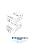
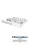
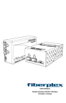
USER MANUAL Rack Mount Chassis RMC‐2101 / RMC‐3101 / RMC‐3102 Warning for Your Protection 1. Read these instructions. 2. Keep these instructions. 3. Heed all warnings. 4. Follow all instructions. 5. Do not use this apparatus near water. 6. Clean only with a dry cloth. 7. Do not block any of the ventilation openings. Install in accordance with the manufacturer’s instructions. 8. Do not install near any heat sources such as radiators, heat registers, stoves, or other apparatus (including amplifiers) that produce heat. 9. Only use attachments/accessories specified by the manufacturer. 10. Unplug this apparatus during lightning storms or when unused for long periods of time. 11. Refer all servicing to qualified service personnel. Servicing is required when the apparatus has been damaged in any way, such as power‐supply cord or plug is damaged, liquid has been spilled or objects have fallen into the apparatus, the apparatus has been exposed to rain or moisture, does not operate normally, or has been dropped. The apparatus shall not be exposed to dripping or splashing. No objects filled with liquids, such as vases, shall be placed on the apparatus. “WARNING: To reduce the risk of fire or electric shock, do not expose this apparatus to rain or moisture.” General Installation Instructions Please consider these general instructions in addition to any product‐specific instructions in the “Installation” chapter of this manual. Unpacking Check the equipment for any transport damage. If the unit is mechanically damaged, if liquids have been spilled or if objects have fallen into the unit, it must not be connected to the AC power outlet, or it must be immediately disconnected by unplugging the power cable. Repair must only be performed by trained personnel in accordance with the applicable regulations. Installation Site Install the unit in a place where the following conditions are met: The temperature and the relative humidity of the operating environment must be within the specified limits during operation of the unit. Values specified are applicable to the air inlets of the unit. Condensation may not be present during operation. If the unit is installed in a location subject to large variations of ambient temperature (e.g. in an OB‐van), appropriate precautions must be taken. Unobstructed air flow is essential for proper operation. Ventilation openings of the unit are a functional part of the design and must not be obstructed in any way during operation (e.g. ‐ by objects placed upon them, placement of the unit on a soft surface, or improper installation of the unit within a rack or piece of furniture). The unit must not be unduly exposed to external heat sources (direct sunlight, spot lights). Ambient Temperature Units and systems by FiberPlex are generally designed for an ambient temperature range (i.e. temperature of the incoming air) of +5...+40 °C. When rack mounting the units, the following facts must be considered: The permissible ambient temperature range for operation of the semiconductor components is 0 °C to +70 °C (commercial temperature range for operation). The air flow through the installation must allow exhaust air to remain cooler than 70 °C at all times. Average temperature increase of the cooling air shall be about 20 C°, allowing for an additional maximum 10 C° increase at the hottest components. If the cooling function of the installation must be monitored (e.g. for fan failure or illumination with spot lamps), the exhaust air temperature must be measured directly above the modules at several places within the enclosure. Grounding and Power Supply Grounding of units with mains supply (class I equipment) is performed via the protective earth (PE) conductor integrated in the mains cable. Units with battery operation (< 60 V, class III equipment) must be earthed separately. Grounding the unit is one of the measures for protection against electrical shock hazard (dangerous body currents). Hazardous voltage may not only be caused by defective power supply insulation, but may also be introduced by the connected audio or control cables. This equipment may require the use of a different line cord, attachment plug, or both, depending on the available power source at installation. If the attachment plug needs to be changed, refer servicing to qualified personnel. Class I Equipment (Mains Operation) Should the equipment be delivered without a matching mains cable, the latter has to be prepared by a trained person using the attached female plug (IEC320/C13 or IEC320/C19) with respect to the applicable regulations in your country. Before connecting the equipment to the AC power outlet, check that the local line voltage matches the equipment rating (voltage, frequency) within the admissible tolerance. The equipment fuses must be rated in accordance with the specifications on the equipment. Equipment supplied with a 3‐pole appliance inlet (protection conforming to class I equipment) must be connected to a 3‐pole AC power outlet so that the equipment cabinet is connected to the protective earth. WARNING: If the ground is defeated, certain fault conditions in the unit or in the system to which it is connected can result in full line voltage between chassis and earth ground. Severe injury or death can then result if the chassis and earth ground are touched simultaneously. Warranty, Service and Terms and Conditions of Sale For information about Warranty or Service information, please see our published ‘Terms and Conditions of Sale’. This document is available on fiberplex.com or can be obtained by requesting it from [email protected] or calling 301.604.0100. Disposal Disposal of Packing Materials The packing materials have been selected with environmental and disposal issues in mind. All packing material can be recycled. Recycling packing saves raw materials and reduces the volume of waste. If you need to dispose of the transport packing materials, recycling is encouraged. Disposal of Used Equipment Used equipment contains valuable raw materials as well as substances that must be disposed of professionally. Please dispose of used equipment via an authorized specialist dealer or via the public waste disposal system, ensuring any material that can be recycled has been. Please take care that your used equipment cannot be abused. After having disconnected your used equipment from the mains supply, make sure that the mains connector and the mains cable are made useless. Disclaimer The information in this document has been carefully checked and is believed to be accurate at the time of publication. However, no liability is assumed by FiberPlex for inaccuracies, errors, or omissions, nor for loss or damage resulting either directly or indirectly from use of the information contained herein. Introduction The FiberPlex Technologies RMC‐2101 / RMC‐3101 / RMC‐3102 chassis are standard 19” rack mountable chassis. Each chassis provides up to nine (9) available slots for any FiberPlex fiber optic isolator (FOI) or telephone disconnect unit. Note that the size 3 and TDU units will not fit in the RMC‐2101 chassis. The tenth available slot must be occupied by a power supply module. Each chassis will be shipped with one power supply module (PSM). A second power supply module may also be added for system power redundancy, leaving eight (8) available slots for the installation various combinations of FOI units. If the first power supply module fails, the second will assume the entire system load and carry on normally. The failed power supply module may be hot swapped with a new one without interruption of FOI operation. Each FOI must be mated to a chassis mount adapter (CMA), which interfaces the FOI with the slot and assures correct alignment of the isolator power connector and the chassis power bus. Key Features Up to nine fiber optic isolators may be mounted per chassis. Each fiber optic isolator is accessible and removable through the front of the chassis in the RMC‐ 3101 and on the rear in the RMC‐2101. One PSM‐2010 or ‐3010 power supply and power cord is included with chassis. Power redundancy is available through an optional second power supply module. A cable bay is provided below the module bay for cable routing on the RMC‐3101 and RMC‐3102. Enhanced air flow through two exhaust fans and a vented panel. Chassis Model Overview The following table is a summary of the various chassis models and features. Rack Height ST Optical Patch Panel Accommodate Size 2 & 4 FOI Models Accommodate Size 3 FOI and TDU Models Power Supply Model (1 included) Chassis Mount Adapter (sold separately) RMC‐2101 RMC‐2101R RMC‐3101 RMC‐3101R RMC‐3102 RMC‐3102R RFI Suppressed Power Model Number X X X 2U 2U 3U 3U 3U 3U X X X X X X X X X X X X PSM‐2010 PSM‐2010 PSM‐3010 PSM‐3010 PSM‐3010 PSM‐3010 CMA‐2001 CMA‐2001 CMA‐3002 CMA‐3002 CMA‐3002 CMA‐3002 Getting Started Initial Inspection Immediately upon receipt, inspect the shipping container for damage. The container should be retained until the shipment has been checked for completeness and the equipment has been checked mechanically and electrically. If the shipment is incomplete, if there is mechanical damage, or if the unit fails to operate notify FiberPlex and make the shipping materials available for the carrier's inspection. Chassis Mounting Mount the empty chassis using fasteners appropriate to your standard 19” rack enclosure. All four (4) mounting points MUST be utilized. Ensure that there exists adequate clearance for front and rear ventilation. The chassis should be located in an environment where an ambient temperature between 0° and 50° C can be maintained. A typical 78 inch equipment rack should be limited to a maximum of 17 RMC‐2101 chassis. When the model RMC‐3101 is preferred, then installation of a maximum of 12 units is advised. The worst case heat dissipation for 17 units is 2.3kW total; forced air rack ventilation is recommended. Power Requirements & PSM Mounting The power supply modules (PSM‐2010 / PSM‐3010) accept voltages from 100‐240 VAC, 50/60 Hz. Maximum power consumption is 125W per module. Although the power supply modules are designed to be hot swappable, it is optimal practice to insert a module into the chassis prior to the application of AC power. The power supplies must be installed in the slot left most slot when viewing the insertion end of the respective model chassis. A secondary redundant power supply may be installed in the next slot to the right. To access the fuses, disconnect power cord, and remove the power supply unit from the chassis. Replacement fuses must have the required current rating and must be of the specified type. Use of repaired fuses and/or bypass of the fuse holders is not recommended and will void the warranty. The system power requirement for a 17‐unit (maximum) rack configuration is 115 VAC @ 20 Amps; if supplied with 230 VAC, 10 Amps is required. Figure 1 PSM‐2010 install into the RMC‐2101 from the rear Figure 2 PSM‐3010 install into the RMC‐3101 from the front Power Supply Module Fuse Replacement The power supply modules are each protected by a single 2A time‐delay fuse (Littlefuse model 218.002 Slo‐ Blo). Replacement of the fuse requires the power cord to be disconnected from the power supply power inlet. Slide open the integral fuse holder, remove the blown fuse and replace. A spare fuse is stored on the outer position of the fuse holder. Replace only with identical or equivalent time‐delay fuse. Figure 3 Fuse replacement in both the PSM‐2010 and PSM‐3010 Inserting FOI Modules When chassis mounting is desired, the isolator must first be attached to a Chassis Mounting Adapter (CMA). Two CMA models are available. Model CMA‐2001 provides for FOI installation within the RMC‐2101 chassis and the model CMA‐3002 provides installation within the RMC‐3101 and RMC‐3102 chassis. Both CMA models attach to the isolator module in an identical manner. Two mounting holes on the CMA base plate flange align with corresponding threaded holes located on the isolator module above the power jack. One (1) threaded banana plug and one (1) 6‐32 thread Phillips pan‐head screw are supplied to mate the FOI to the adapter. The FOI unit may now be inserted into any available slot. The CMA will insure perfect alignment of the FOI and the chassis backplane connector. Figure 4 Attach FOI to appropriate CMA using banana plug and Philips screw Figure 5 FOI installs into the RMC‐2101 from the rear Figure 6 FOI installs into the RMC‐3101 from the front Features RMC‐2101 Front Features Figure 7 RMC‐2101 Front Face 1 Chassis Ventilation Fans (x2) – These fans provide forced air cooling to the mounted components. RMC‐2101 Rear Features Figure 8 RMC‐2101 Rear Face Power Supply Installation Positions (x2) – The first two chassis positions are spaced appropriately for the installation of redundant PSM‐2010 power supplies, which are hot‐swappable. FOI modules can be placed in this position if only a single power supply is used allowing for a total of 9 FOI modules. 2 3 FOI Module Installation Positions (x8) – The remaining positions are spaced appropriately for the installation of up to 8 FOI modules on their CMA‐2001 adapter plates. 4 Card Guides, Upper and Lower – Power supply and FOI modules are aligned with the guides for proper insertion with the mating connectors in the chassis wall. Module Grounding and Retention Fitting – All modules are equipped with a grounding lug which engages blind into this jack upon installation. This also aids retention of each module within the chassis. 5 Power Connector Jack – DC power is tapped from the power supplies and distributed to the FOI units via these connectors on a single bus. Designed for the blind mating application, the interface provides retention of the units as well. 6 RMC‐3101 Front Features with Cover Figure 9 RMC‐3101 Front Face with Cover Installed Front Cover Retention Thumbscrews (x2) – A pair of knurled thumbscrews allow access to the module mounting cavity without the use of tools. To remove, turn CCW to loosen, then continue to rotate the inner retention levers to disengage the mounting blocks. Installation of the front cover requires alignment of the retention levers to clear the inner blocks prior to replacement of the cover. 1 2 Front Ventilation Openings – These shall be kept clear of debris, papers, labels, etc. to allow cooling airflow required by the chassis components. RMC‐3101 Rear Face Figure 10 RMC‐3101 Rear Face 8 Chassis Ventilation Fans (x2) – These fans provide forced air cooling to the mounted components. 9 Grounding Lugs (x2) – Provisioned for a functional chassis ground from either side, the grounding points are either left or right. The unit ships with hardware on the right side. 10 Cable Routing Tray – Cable and optical fiber runs may be laid here to clear the cooling fan assembly. Allows for clean rear exit of all cables. RMC‐3101 Front without Cover Figure 11 RMC‐3101 Front Face, Cover Removed Power Supply Installation Positions (x2) – The first two chassis positions are spaced appropriately for the installation of redundant PSM‐3010 power supplies, which are hot‐swappable. FOI modules can be placed in this position if only a single power supply is used allowing for a total of 9 FOI modules. 3 4 FOI Module Installation Positions (x8) – The remaining positions are spaced appropriately for the installation of up to 8 FOI modules on their CMA‐3002 adapter plates. 5 Card Guides, Upper and Lower – Power supply and FOI modules are aligned with the guides for proper insertion with the mating connectors in the chassis wall. Module Grounding and Retention Fitting – All modules are equipped with a grounding lug which engages blind into this jack upon installation. This also aids retention of each module within the chassis. 6 Power Connector Jack – DC power is tapped from the power supplies and distributed to the FOI units via these connectors on a single bus. Designed for the blind mating application, the interface provides retention of the units as well. 7 PSM‐2010/3010 Front Face Figure 12 PSM‐2010 Front Face 1 Power Status LED – Indicates DC output for the power supply. A green LED indicates power good. An audible alarm will sound if one supply in a redundant system has failed. 2 Fuse Access Panel – Allows access to the 5 x 20mm fuse. The AC power path is interrupted when in the open position. 3 AC Mains Power Inlet – Conforming to IEC 320, standard power cords are attached here. PSM‐2010/3010 Rear Face Figure 13 PSM‐2010 Rear Face 4 Power Supply Grounding Plug – Pomona‐type plug provides a functional ground and aids retention of the module within the chassis. 5 Power Connector Plug – DC output to the chassis bus; this also provides retention of the power supply in the installed position. Specifications RMC‐2101 Figure 14 RMC‐2101 Dimensions FAN SPECIFICATIONS Fan Speed Min ‐ ‐ ‐ ‐ ‐ ‐ Air Pressure Air Flow Noise Typ 2500 ‐ ‐ 50.5 1.43 34 Max ‐ 3.5 0.14 ‐ ‐ ‐ Unit RPM mmH2O inH2O CFM m3/min dBA @ 1m PHYSICAL SPECIFICATIONS Case Dimensions RMC‐2101 Rack Spaces 2U Length 11.35 in (288 mm) Width 19 in (483 mm) Height 3.5 in (89 mm) Weight 16 lb (7.25 kg) RMC‐3101 Figure 15 RMC‐3101 Dimensions FAN SPECIFICATIONS Fan Speed Min ‐ ‐ ‐ ‐ ‐ ‐ Air Pressure Air Flow Noise Typ 2500 ‐ ‐ 50.5 1.43 34 Max ‐ 3.5 0.14 ‐ ‐ ‐ Unit RPM mmH2O inH2O CFM m3/min dBA @ 1m PHYSICAL SPECIFICATIONS Case Dimensions RMC‐3101 Rack Spaces 3U Length 12.75 in (234 mm) Width 19 in (483 mm) Height 5.25 in (133 mm) Weight 22 lb (10 kg) PSM‐2010 Figure 16 PSM‐2010 Overall Dimensions PSM‐3010 Figure 17 PSM‐3010 Overall Dimensions ELECTRICAL SPECIFICATIONS Input Output Voltage Frequency Power Voltage Supply Current Power Min 100 50 ‐ ‐ ‐ ‐ Typ ‐ ‐ ‐ 9 ‐ ‐ Max 240 60 125 ‐ 8.3 76.5 Unit VAC Hz W VDC A W Min ‐40 0 Typ ‐ ‐ Max 85 50 Unit °C °C ENVIRONMENTAL SPECIFICATIONS Storage Temperature Operating Temperature PHYSICAL SPECIFICATIONS Case Dimensions PSM‐2010 PSM‐3010 Length 6.375 in (162 mm) 9.56 in (243 mm) Width 1.57 in (40 mm) 1.57 in (40 mm) Height 2.84 in (72 mm) 3.49 in (88 mm) Weight 1.6 lb (0.7 kg) 1.6 lb (0.7 kg) UMRMC3010 150303 18040-412 Guilford Rd. • Annapolis Junction, MD 20701 fiberplex.com • [email protected] • 301.604.0100