1
FX Series Programmable Controllers
4.10.1
Devices in Detail 4
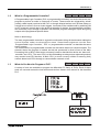
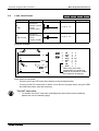
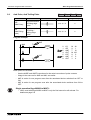
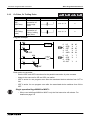
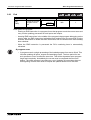
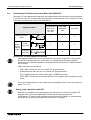
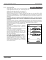
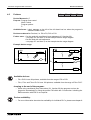
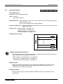
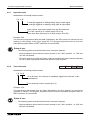
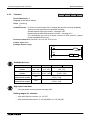
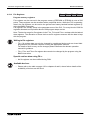
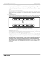
General/ Latched 16bit UP Counters
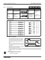
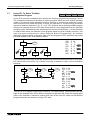
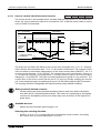
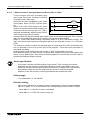
The current value of the counter increases
each time coil C0 is turned ON by X11. The
output contact is activated when the coil is
turned ON for the tenth time (see diagram).
After this, the counter data remains unchanged
when X11 is turned ON. The counter current
value is reset to ‘0’ (zero) when the RST
instruction is executed by turning ON X10 in
the example. The output contact Y0 is also
reset at the same time.
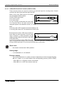
Counters can be set directly using constant K
or indirectly by using data stored in a data
register (ex. D). In an indirect setting, the
d es ig n a ti o n o f D 10 f o r e x am pl e , w h ic h
contains the value “123” has the same effect
as a setting of “K123”.
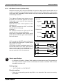
If a value greater than the counter setting is
written to a current value register, the counter
counts up when the next input is turned ON.
This is true for all types of counters.
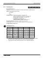
Generally, the count input frequency should be
around several cycles per second.
X10
RST C0
X11
C0
K10
Y0
C0
X10
X11
0
1
2
3
4
5
6
7
8
9
10
Y0
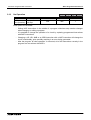
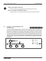
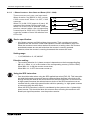
Battery backed/latched counters:
• Counters which are battery backed/ latched are able to retain their status information,
even after the PLC has been powered down. This means on re-powering up, the latched
counters can immediately resume from where they were at the time of the original PLC
power down.
Available devices:
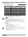
• Please see the information table on page 4-19.
4-20