1
MITSUBISHI ELECTRIC
MELSEC FX Series
Programmable Logic Controllers
Software Manual
FX-PCS/WIN-E
Art. no.: 068560
15 04 2003
JY992D66501
Version E
MITSUBISHI ELECTRIC
INDUSTRIAL AUTOMATION
FX Series Programmable Controllers
FX-PCS/WIN-E
Software Manual
Manual number
:
JY992D66501
Manual revision
:
E
Date
:
April 2003
Foreword
•
This manual contains text, diagrams and explanations which will guide the reader in the correct
installation and operation of the FX-PCS/WIN-E.
•
Before attempting to install or use the FX-PCS/WIN-E this manual should be read and understood.
•
If in doubt at any stage of the installation of the FX-PCS-/WIN-E always consult a professional electrical
engineer who is qualified and trained to the local and national standards which apply to the installation
site.
•
If in doubt about the operation or use of the FX-PCS/WIN-E please consult the nearest Mitsubishi Electric
distributor.
•
This manual is subject to change without notice.
i
FX Series Programmable Controllers
Registration
•
Microsoft Windows, MS, MS-Windows 3.1, Windows 95, Windows 98, Windows Millennium
Edition, Windows NT 4.0 Workstation, Windows 2000 and Windows XP are either registered
trademarks or trademarks of Microsoft Corporation in the United States and/or other countries.
•
The company name and the product name to be described in this manual are the registered trademarks
or trademarks of each company.
ii
FX Series Programmable Controllers
FAX BACK
Mitsubishi has a world wide reputation for its efforts in continually developing and pushing back
the frontiers of industrial automation. What is sometimes overlooked by the user is the care
and attention to detail that is taken with the documentation. However, to continue this process
of improvement, the comments of the Mitsubishi users are always welcomed. This page has
been designed for you, the reader, to fill in your comments and fax them back to us. We look
forward to hearing from you.
Fax numbers:
Your name: ...................................................
Mitsubishi Electric....
.....................................................................
America
(01) 847-478-2253
Your company: .............................................
Australia
(02) 638-7072
.....................................................................
Germany
(0 21 02) 4 86-1 12
Your location:................................................
Spain
(34) 93-589-1579
.....................................................................
United Kingdom
(01707) 278-695
Please tick the box of your choice
What condition did the manual arrive in?
!Good
!Minor damage
Will you be using a folder to store the manual? !Yes
!No
What do you think to the manual presentation?!Tidy
!Unfriendly
Are the explanations understandable?
!Yes
!Not too bad
!Unusable
!Unusable
Which explanation was most difficult to understand: ..................................................................
....................................................................................................................................................
Are there any diagrams which are not clear?
!Yes
!No
If so,which: ..................................................................................................................................
What do you think to the manual layout?
!Good
!Not too bad
!Unhelpful
If there one thing you would like to see improved, what is it? .....................................................
....................................................................................................................................................
....................................................................................................................................................
Could you find the information you required easily using the index and/or the contents, if
possible please identify your experience: ...................................................................................
....................................................................................................................................................
....................................................................................................................................................
....................................................................................................................................................
....................................................................................................................................................
Do you have any comments in general about the Mitsubishi manuals? .....................................
....................................................................................................................................................
....................................................................................................................................................
....................................................................................................................................................
....................................................................................................................................................
Thank you for taking the time to fill out this questionnaire. We hope you found both the product
and this manual easy to use.
iii
FX Series Programmable Controllers
iv
FX Series Programmable Controllers
Guidelines for the Safety of the User and Protection of the Programmable
Controller
This manual provides information for the use of the FX Series Communication Unit. The manual has been
written to be used by trained and competent personnel. The definition of such a person or persons is as
follows;
a ) Any engineer who is responsible for the planning, design and construction of automatic equipment
using the product associated with this manual should be of a competent nature, trained and qualified
to the local and national standards required to fulfill that role. These engineers should be fully aware
of all aspects of safety with regards to automated equipment.
b ) Any commissioning or service engineer must be of a competent nature, trained and qualified to the
local and national standards required to fulfill that job. These engineers should also be trained in the
use and maintenance of the completed product. This includes being completely familiar with all
associated documentation for the applicable product. All maintenance should be carried out in
accordance with established safety practices.
c ) All operators of the completed equipment (see Note) should be trained to use this product in a safe
manner in compliance to established safety practices. The operators should also be familiar with
documentation which is connected with the actual operation of the completed equipment.
Note: the term ‘completed equipment’ refers to a third party constructed device which contains or uses the
product associated with this manual.
Notes on the Symbols Used in this Manual
At various times throughout this manual certain symbols will be used to highlight points of information which
are intended to ensure the users personal safety and protect the integrity of equipment. Whenever any of the
following symbols are encountered its associated note must be read and understood. Each of the symbols
used will now be listed with a brief description of its meaning.
Hardware Warnings
1 )Indicates that the identified danger WILL cause physical and property damage.
2 )Indicates that the identified danger could POSSIBLY cause physical and property damage.
3 )Indicates a point of further interest or further explanation.
Software Warnings
1 )Indicates special care must be taken when using this element of software.
2 )Indicates a special point which the user of the associate software element should be aware of.
3 )Indicates a point of interest or further explanation.
v
FX Series Programmable Controllers
•
Under no circumstances will Mitsubishi Electric be liable responsible for any consequential damage that
may arise as a result of the installation or use of this equipment.
•
All examples and diagrams shown in this manual are intended only as an aid to understanding the text,
not to guarantee operation. Mitsubishi Electric will accept no responsibility for actual use of the product
based on these illustrative examples.
•
Please contact a Mitsubishi Electric distributor for more information concerning applications in life critical
situations or high reliability.
Abbreviations
The following definitions or abbreviations will be used throughout this manual.
•
The FX-PCS/WIN-E software will be referred to as the FX-PCS/WIN-E or FXGP/WIN-E.
•
The FX0, FX0S, FX0N, FX, FX2C, FX1S, FX1N, FX2N and FX2NC Series PLC may be referred to as the FX
Series PLC or FX Series PLC.
•
Input/Output may be referred to as I/O.
•
Personal Computer may be referred to as PC
•
Microsoft Windows, Windows 3.1, Windows 95, Windows 98, Windows Millennium Edition,
Windows NT 4.0 Workstation, Windows 2000 and Windows XP may be referred to generically as
Windows.
vi
FX Series Programmable Controllers
Contents
CONTENTS
1. Introduction ................................................................................................... 1-1
1.1 Main Software Features ................................................................................................. 1-1
1.2 Contents of Product Package and System Configuration .............................................. 1-3
1.2.1 Contents of product package .........................................................................................................1-3
1.2.2 Operation environment .................................................................................................................1-3
1.3 Compatibility of Data File Types .................................................................................... 1-5
1.4 Comment Control ........................................................................................................... 1-7
2. Installing FXGP/WIN-E .................................................................................. 2-1
2.1 Install Procedure (for Windows 3.1) ............................................................................... 2-1
2.2 Install Procedure (for Windows 95 or after) .................................................................... 2-2
3. Main Operation .............................................................................................. 3-1
3.1 Starting method .............................................................................................................. 3-1
3.1.1 Starting FXGP/WIN-E for Windows 3.1 .........................................................................................3-1
3.1.2 Starting FXGP/WIN-E for Windows 95 or After .............................................................................3-1
3.2 Initial Screen Operation ................................................................................................. 3-2
3.3 Main screens .................................................................................................................. 3-3
3.4 Terminating method (Exit) .............................................................................................. 3-4
4. Work Windows and their Functions ............................................................... 4-1
4.1 Construction and Types of Windows .............................................................................. 4-1
4.1.1 Construction of windows and relation between windows ..............................................................4-1
4.1.2 Handling of opened FXGP/WIN-E softwares at a time ..................................................................4-2
4.1.3 Split window ...................................................................................................................................4-3
4.1.4 Selecting a window from tool menu ...............................................................................................4-4
4.2 Functions of the Programming Window Group: View .................................................... 4-5
4.3 Functions of the Comment Window Group: View → Comment View ............................ 4-6
4.4 Functions of the Register Window: View → Register View ........................................... 4-8
4.5 Functions of the Device List Window Group: View → ................................................... 4−9
4.6 Functions of the Sampling Trace Window Group: PLC → Sampling Trace ................ 4-10
4.7 Functions of Device Monitor Window: Monitor/Test → ................................................ 4−11
5. Guidance of Main Operations ....................................................................... 5-1
5.1 Startup/Edit/window display ........................................................................................... 5-1
5.2 Program ......................................................................................................................... 5-2
5.3 Ladder circuit ................................................................................................................. 5-3
5.4 List ................................................................................................................................. 5-4
5.5 SFC ................................................................................................................................ 5-4
5.6 Instruction input .............................................................................................................. 5-4
5.7 PLC ................................................................................................................................ 5-5
5.8 Monitor ........................................................................................................................... 5-6
5.9 Comment ....................................................................................................................... 5-6
5.10 Printer .......................................................................................................................... 5-7
5.11 PC ................................................................................................................................ 5-8
5.12 Data compatibility and conversion ............................................................................... 5-8
5.13 Telephone line connection ........................................................................................... 5-8
5.14 Others .......................................................................................................................... 5-9
vii
Contents
FX Series Programmable Controllers
6. Menu Bar Commands ................................................................................... 6-1
6.1 File Menu Functions ....................................................................................................... 6-2
6.1.1 New ...............................................................................................................................................6-2
6.1.2 Open ..............................................................................................................................................6-3
6.1.3 Close and Open ............................................................................................................................6-5
6.1.4 Save ..............................................................................................................................................6-6
6.1.5 Save As .........................................................................................................................................6-7
6.1.6 Print ...............................................................................................................................................6-8
6.1.7 Print All ........................................................................................................................................6-16
6.1.8 Page Setup ..................................................................................................................................6-17
6.1.9 Print Preview ...............................................................................................................................6-18
6.1.10 Printer Setup .............................................................................................................................6-20
6.1.11 Displaying file use history .........................................................................................................6-20
6.1.12 Exit ............................................................................................................................................6-21
6.2 Edit Menu Functions .................................................................................................... 6-22
6.2.1 Undo ............................................................................................................................................6-23
6.2.2 Cut ...............................................................................................................................................6-23
6.2.3 Copy ............................................................................................................................................6-23
6.2.4 Paste ...........................................................................................................................................6-23
6.2.5 Delete ..........................................................................................................................................6-23
6.2.6 Line Delete ..................................................................................................................................6-24
6.2.7 Line Insert ....................................................................................................................................6-25
6.2.8 Block Select .................................................................................................................................6-26
6.2.9 NOP Overwrite ...........................................................................................................................6-28
6.2.10 NOP Insert ................................................................................................................................6-28
6.2.11 NOP Remove ...........................................................................................................................6-29
6.2.12 Device Name .............................................................................................................................6-30
6.2.13 Device Comment .......................................................................................................................6-31
6.2.14 Coil Comment ............................................................................................................................6-32
6.2.15 Block Comment .........................................................................................................................6-32
6.2.16 Device Registration ...................................................................................................................6-34
6.2.17 Edit cancel .................................................................................................................................6-35
6.3 Tools Menu Functions .................................................................................................. 6-36
6.3.1 Contact ........................................................................................................................................6-37
6.3.2 Coil ..............................................................................................................................................6-39
6.3.3 Function .......................................................................................................................................6-41
6.3.4 Wire .............................................................................................................................................6-44
6.3.5 Instruction ....................................................................................................................................6-46
6.3.6 All Clear .......................................................................................................................................6-47
6.3.7 Convert ........................................................................................................................................6-48
6.3.8 Default comments for special M/D ...............................................................................................6-49
6.3.9 Comment settings ........................................................................................................................6-50
6.3.10 Setting of step of comment ........................................................................................................6-52
6.4 Search Menu Functions ............................................................................................... 6-53
6.4.1 Go to Top, Go to End ..................................................................................................................6-54
6.4.2 Device Name Search ...................................................................................................................6-55
6.4.3 Device Search .............................................................................................................................6-55
6.4.4 Instruction Search ........................................................................................................................6-56
6.4.5 Contact/Coil Search .....................................................................................................................6-56
6.4.6 Go to Step ...................................................................................................................................6-57
6.4.7 Go to State ..................................................................................................................................6-57
6.4.8 Character Search ........................................................................................................................6-58
6.4.9 Character Exchange ....................................................................................................................6-58
6.4.10 Change Device Number ............................................................................................................6-59
6.4.11 Change Bit Device .....................................................................................................................6-60
6.4.12 Swap Device Number ................................................................................................................6-60
6.4.13 Tag Set ......................................................................................................................................6-61
6.4.14 Tag Jump ..................................................................................................................................6-61
viii
FX Series Programmable Controllers
Contents
6.5 View Menu Functions ................................................................................................... 6-62
6.5.1 Ladder View ................................................................................................................................6-63
6.5.2 Instruction View ...........................................................................................................................6-64
6.5.3 SFC View .....................................................................................................................................6-65
6.5.4 Inner Ladder View .......................................................................................................................6-66
6.5.5 Comment View ............................................................................................................................6-67
6.5.6 Register View ..............................................................................................................................6-71
6.5.7 Tool Bar Status Bar Function Keys .............................................................................................6-75
6.5.8 Palette .........................................................................................................................................6-76
6.5.9 Contact/Coil List ..........................................................................................................................6-77
6.5.10 Device Used List ........................................................................................................................6-77
6.5.11 TC Setting List ...........................................................................................................................6-78
6.5.12 Comment display .......................................................................................................................6-79
6.5.13 Display Setting ...........................................................................................................................6-82
6.5.14 Zoom .........................................................................................................................................6-82
6.6 PLC Menu Functions ................................................................................................... 6-83
6.6.1 Transfers .....................................................................................................................................6-84
6.6.2 Register Data Transfers ..............................................................................................................6-86
6.6.3 PLC Memory Clear ......................................................................................................................6-88
6.6.4 Serial Setting (D8120) .................................................................................................................6-88
6.6.5 PLC Keyword Current or Delete ..................................................................................................6-89
6.6.6 Runtime Program Changes .........................................................................................................6-91
6.6.7 Remote Run/Stop ........................................................................................................................6-94
6.6.8 PLC Diagnostics ..........................................................................................................................6-94
6.6.9 Sampling Trace ...........................................................................................................................6-95
6.6.10 Ports ..........................................................................................................................................6-99
6.7 Monitor/Test Menu Functions ..................................................................................... 6-100
6.7.1 Start monitor ..............................................................................................................................6-101
6.7.2 Stop Monitor ..............................................................................................................................6-103
6.7.3 Dynamic Monitor ........................................................................................................................6-104
6.7.4 Entry Device Monitor .................................................................................................................6-105
6.7.5 Forced Y Output ........................................................................................................................6-108
6.7.6 Forced On/Off ............................................................................................................................6-109
6.7.7 Change Current Values .............................................................................................................6-110
6.7.8 Change Setting Values ..............................................................................................................6-112
6.7.9 Display change of monitor data(""") ..................................................................................6-113
6.8 Option Menu Functions .............................................................................................. 6-114
6.8.1 Program Check ..........................................................................................................................6-115
6.8.2 Parameter Settings ....................................................................................................................6-116
6.8.3 Keyword Setting ........................................................................................................................6-119
6.8.4 PLC’s Mode Setting ...................................................................................................................6-119
6.8.5 Serial Setting (Parameter) .........................................................................................................6-120
6.8.6 Printer Title ................................................................................................................................6-121
6.8.7 Device range Setting .................................................................................................................6-122
6.8.8 Comment Move .........................................................................................................................6-123
6.8.9 PLC Type Change .....................................................................................................................6-124
6.8.10 Preferences .............................................................................................................................6-125
6.8.11 EPROM Transfer .....................................................................................................................6-126
6.8.12 Font .........................................................................................................................................6-127
6.9 Window Menu Functions ............................................................................................ 6-128
6.10 Help Menu Functions ............................................................................................... 6-129
ix
Contents
FX Series Programmable Controllers
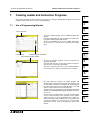
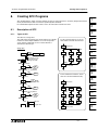
7. Creating Ladder and Instruction Programs ................................................... 7-1
7.1 Use of Programming Window ....................................................................................... 7-1
7.2 Creating Ladder Programs ............................................................................................. 7-2
7.2.1 Main operations necessary for entering ladder circuit symbols .....................................................7-2
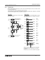
7.2.2 Instruction type ladder circuit entry ..............................................................................................7-11
7.2.3 Essentials for programming .........................................................................................................7-13
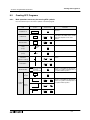
7.2.4 Creating ladder circuit ladder diagram .........................................................................................7-16
7.3 Creating Instruction List Program ................................................................................. 7-20
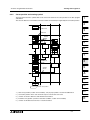
7.3.1 Main operations necessary for entering instruction words ..........................................................7-20
7.3.2 Creating instruction list ................................................................................................................7-29
8. Creating SFC Programs ................................................................................ 8-1
8.1 Description of SFC ......................................................................................................... 8-1
8.1.1 Types of SFC ................................................................................................................................8-1
8.1.2 Program types ...............................................................................................................................8-2
8.1.3 Structure of SFC section ...............................................................................................................8-3
8.2 Creating SFC Programs ................................................................................................. 8-4
8.2.1 Main operations necessary for entering SFC symbols ..................................................................8-4
8.2.2 Cursor position and entering symbol .............................................................................................8-5
8.2.3 Main items necessary for creating SFC .........................................................................................8-6
8.2.4 Creating SFC .................................................................................................................................8-9
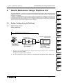
9. Remote Maintenance Using a Telephone Line ............................................. 9-1
9.1 System Configuration and Functions ............................................................................. 9-1
9.1.1 Remote access to PLC ..................................................................................................................9-1
9.1.2 Sending/receiving files ...................................................................................................................9-3
9.1.3 Caution ..........................................................................................................................................9-4
9.2 Operation Procedures .................................................................................................... 9-5
9.2.1 Remote access to PLC ..................................................................................................................9-5
9.2.2 File transfer ....................................................................................................................................9-7
9.3 Functions on Remote Menu ......................................................................................... 9-10
9.3.1 Connect ......................................................................................................................................9-10
9.3.2 Disconnect ...................................................................................................................................9-14
9.3.3 File transfer .................................................................................................................................9-15
9.3.4 Environment → Modem .............................................................................................................9-17
9.3.5 Environment → Logging File ......................................................................................................9-20
9.4 Data Setting on PLC Side for Remote Access ............................................................. 9-21
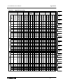
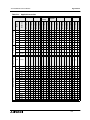
Appendix A:
PLC Device Tables................................................................................... A-1
A-1:
A-2:
A-3:
A-4:
A-5:
A-6:
A-7:
FX0/FX0S Series PLC ..........................................................................................A-2
FX0N Series PLC .................................................................................................A-3
FX Series PLC (Version 2.30 or earlier) ..............................................................A-4
FX (Version 3.07 or later)/FX2C (All version) Series PLC ....................................A-6
FX1S Series PLC .................................................................................................A-8
FX1N Series PLC .................................................................................................A-9
FX2N/FX2NC Series PLC....................................................................................A-11
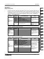
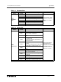
Appendix B:
PLC Instruction Tables ............................................................................. B-1
B-1: Basic Program Instruction Table .........................................................................B-1
B-2: SFC (STL) Program Instruction Table .................................................................B-1
B-3: Applied Instruction Table .....................................................................................B-2
x
FX Series Programmable Controllers
Contents
Appendix C:
Error Cord of PLC..................................................................................... C-1
Appendix D:
File converter............................................................................................ D-1
Appendix E:
Associated Manuals ................................................................................. E-1
xi
Contents
FX Series Programmable Controllers
xii
FX Series Programmable Controllers
1
Introduction
1
2
Installing FXGP/WIN-E
2
3
Main Operation
3
4
Work Windows and their Functions
4
5
Guidance of Basic Operations
5
6
Menu Bar Commands and their Functions
6
7
Creating Ladder and Instruction Programs
7
8
Creating SFC Programs
8
9
Remote Maintenance Using Telephone Line
9
A
Appendix A: Device Lists
A
B
Appendix B: Instruction List
B
C
Appendix C: Error Code Tables
C
D
Appendix D: File Convertor
D
E
Appendix D: Associated Manuals
E
FX Series Programmable Controllers
Introduction 1
1
Introduction
2
Installing FXGP/WIN-E
3
Main Operation
4
Work Windows and their Functions
5
Guidance of Basic Operations
6
Menu Bar Commands and their Functions
7
Creating Ladder and Instruction Programs
8
Creating SFC Programs
9
Remote Maintenance Using Telephone Line
A
Appendix A: Device Lists
B
Appendix B: Instruction List
C
Appendix C: Error Code Tables
D
Appendix D: File Convertor
E
Appendix D: Associated Manuals
FX Series Programmable Controllers
1.
Introduction 1
Introduction
This software manual describes the outline connection of the FX-PCS/WIN-E software and the construction of
the hardware system.
In addition, this manual describes the connection of various units and utilization of various the software
functions, such as data file compatibility. Please read this manual before installing the software.
1.1
Main Software Features
FX-PCS/WIN-E is designed for the creation of programs used on Mitsubishi FX series PLC. This software
runs on MS-Windows 3.1, Windows 95, Windows 98, Windows Millennium Edition, Windows NT 4.0
Workstation, Windows 2000, and Windows XP.
1
2
3
4
Programming:
•
Three types of programming windows
Three types of programming tools are available for simultaneous operation. They are the ladder program
edit window, list program edit window, and SFC program edit window. You can enter or edit data while
switching the active window between the three different methods of programing.
•
Selection of the operation type in creating ladder diagrams
To create ladder diagrams via the ladder diagram editing window, you can use the conventional keyboard
operation method. Using this method, use function keys to enter in ladder symbols. In addition to this
conventional operation method, use the mouse operation method. To support the mouse operation
method, there is a floating pallet of ladder symbols, menu commands, and function key guides.
In addition, use the list editing window, You can create ladder diagrams by directly entering instructions.
•
Importance placed on keyboard operation
In some work places, the use of a mouse or pointing device may be difficult, however considering such a
problem, we have designed this software so that most of operation can be performed using the keyboard.
•
6
7
Various tools for selecting instructions from list
This software has various tools that facilitate entry of instructions, such as contact symbols, coil
instructions, and application instructions.
Particularly for application instruction entry, the list of instructions will be displayed, and desired
instructions can be selected from the list. Such interactive functionality will facilitate instruction entry
operation.
•
5
Entire ladder diagram edit function
8
9
A
Modifying part of the diagram while looking the front and rear of the ladder block currently edited.
•
Splitting screen into two
Splitting the ladder diagram editing window, ladder circuit monitoring window, comment editing window,
etc. into two (upper and lower windows) using the split handle at the lower section of the screen is
possible. Each window can display the different sections of the document, and each screen can be
scrolled individually. Use this function to display the separate sections of a document concurrently, or to
monitor two sections simultaneously.
B
C
D
E
1-1
FX Series Programmable Controllers
Introduction 1
Monitoring, connection via telephone line, and others:
•
Monitoring function
•
Remote access to the FX1S, FX1N, FX2N and FX2NC Series PLC through telephone line
Using the ladder program edit window and SFC program edit window, directly monitor the PLC status.
Connect the FX1S, FX1N, FX2N and FX2NC Series PLC to the PC using the modem and telephone line.
You can transfer or monitor the programs through the telephone line even if the PLC is away from the PC.
This software has a telephone line connection and remote station control function, etc.
In addition, if two PCs are connected to each other through the telephone line, data files can be
transferred between PCs.
•
Activation of two or more application programs
The FX-PCS/WIN can activate two or more application programs at the same time, therefore, the uses
can display another program by switching the active window, and move or copy data between the
programs using the cut and paste functions
•
Preview of printed documents
Before printing, preview the images of the printed documents, such as ladder diagrams, command lists,
SFC diagrams, or other printable data.
1-2
FX Series Programmable Controllers
Introduction 1
1.2
Contents of Product Package and System Configuration
1.2.1
Contents of product package
1
The FX-PCS/WIN-E software package contains the following items:
1 ) 3.5- inch floppy disks (1.44 MB) (system disks that can activate the SW0PC- FXGP/ WIN- E system),
2 disks
2
2 ) This operation manual
The cable connecting the PC to the PLC and the interface unit are optional. Prepare a cable and interface unit
applicable to the system, while referring to the configuration shown on the next page.
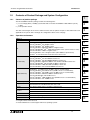
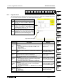
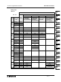
1.2.2
3
4
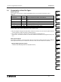
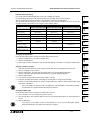
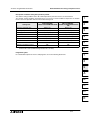
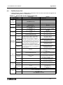
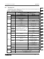
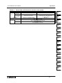
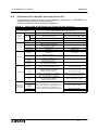
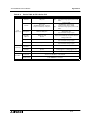
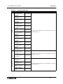
Operation environment
Table:1.1
Item
Description
OS
MS-Windows 3.1 (386 enhance mode) English version
Microsoft Windows 95*1 English version
Microsoft Windows 98*1 English version
Microsoft Windows Millennium Edition*1 English version
Microsoft WindowsNT 4.0*1*2 Workstation English version (Service Pack 3 or later)
Microsoft Windows 2000*1*2 English version
Microsoft Windows XP*1*2 English version (Home Edition or professional)
Operation of each OS shall be assured in the PC to be used.
PC main body
MS-Windows 3.1: 804 6SX or better one
Microsoft Windows 95: CPU i486SX or better one
Microsoft Windows 98: CPU i486DX (66 MHz) or better one
Microsoft Windows Millennium Edition: CPU Pentium 150 MHz or better one
Microsoft WindowsNT 4.0: CPU i486 (25 MHz) or better one
Microsoft Windows 2000: CPU i486 (133 MHz) or better one
Microsoft Windows XP: Pentiumn 300MHz or better one
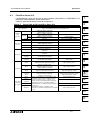
Required memory
MS-Windows 3.1: 8MB or more (16 MB or more is recommended.)
Microsoft Windows 95: 8 MB or more (16 MB or more is recommended.)
Microsoft Windows 98: 16 MB or more (32 MB or more is recommended.)
Microsoft Windows Millennium Edition: 32 MB or more
Microsoft WindowsNT 4.0: 16 MB or more
Microsoft Windows 2000: 32 MB or more (64 MB or more is recommended.)
Microsoft Windows XP: 128MB or more
Hard disk capacity
Free space of 6 MB or more
Floppy disk unit
3.5-inch (2HD) floppy disk drive × 1 unit
A disk formatted as 1.44 MB shall be able to be read.
Display
Video display adaptor whose resolution is VGA or better
Interface
5
6
7
8
9
A
B
C
RS-232C serial interface (COM1 to COM9 shall be able to be changed over.)
D
Printer interface
Printer
Printer in accordance with the OS above
Others
Mouse or other pointing device
Applicable PLC
FX0, FX0S, FX0N, FX (FX2), FX2C, FX1S, FX1N, FX2N and FX2NC series PLC
*1: Long file names cannot be used.
*2: Remote Maintenance cannot support with these operating systems.
1-3
E
Introduction 1
FX Series Programmable Controllers
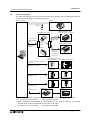
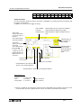
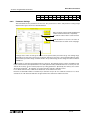
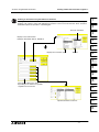
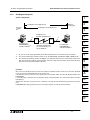
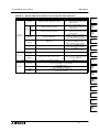
1.2.3
System configuration
The cable connecting the PC to the PLC and the interface unit is optional. Select an appropriate cable and
interface unit while referring to the following description.
<Personal Computer>
<Printer>
<Mouse>
<FX0,FX0S,FX0N,FX1S*1,FX1N*1,
FX2N*1,FX1NC,FX2NC series PLC>
RS-232C/RS-422 converter
FX-232AWC
FX-422CAB0
cable (1.5m)
Use the D-sub 9pin
as the RS-232C part
on PC
FX(RS-422)
<FX1,FX2,FX2C series PLC>
PC
F2-232CAB-1
cable (3m)
FX-232AW
FX-422CAB
cable (0.3m)
FX-422CAB-150
Cable (1.5m)
FX1N-232-BD(FX1S,FX1N)
FX2N-232-BD(FX2N)
<FX1S,FX1N,FX2N Series PLC>
Use the D-sub 9pin as the RS-232C
port on PC
+
FX-232CAB-1 cable (3m)
FX0N-232ADP
<FX1S*2,FX1N*2,FX2N*2,FX1NC,
FX2NC series PLC>
+
F2-232CAB-1 cable
FX2NC-232ADP
<FX1S*2,FX1N*2,FX2N*2,FX1NC,
FX2NC series PLC>
+
FX-232CAB-1 cable
<ROM writer>
<Socket>
F2-232CAB-1 cable
F X
R O M
S O C -1
M IT S U B IS H I
E L E C T R IC
*1 When using FX1S, FX1N or FX2N PLC, PLC can connect to PC via the following expansion board
- FX1S, FX1N PLC: FX1N-422-BD
- FX2N PLC: FX2N-422-BD
*2 When connecting the FX0N-232ADP or FX2NC-232ADP to FX1S, FX1N or FX2N PLC, the following
expansion board need to be installed to the FX1S, FX1N or FX2N PLC.
- FX1S, FX1N PLC: FX1N-CNV-BD
- FX2N PLC: FX2N-CNV-BD
1-4
FX Series Programmable Controllers
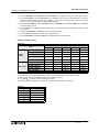
1.3
Introduction 1
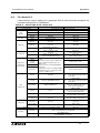
Compatibility of Data File Types
Windows Data files
The programs and comments created by FXGP/WIN-E will be stored using the following file names:
1
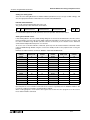
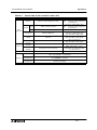
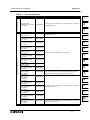
Table:1.2
File name
Extension
2
Data stored in file
Program file *1
PMW
Parameter, program, file register, and comments
Comment file *2
COW
Device comments, block comments, coil comments, and device
name
Register file *1
DMW
Data register and RAM file register
Sampling trace file
STW
Result of sampling trace
Printer title file
PTW
Printing style
Entry device monitor file
RMW
Content of Entry device monitor setting
3
4
For these data files, the special format for the FXGP/WIN-E is used.The SW1PC-FX/EE (AT compatible
machine, DOS version) and the A6GPP/PHP, cannot read these files.
*1: Only the program and register file data will be stored in the memory of the PLC and the optional memory
cassette. Other files will be stored in the peripheral devices.
*2: The comments stored in the comment file are controlled by the peripheral devices.
Refer to Sec. 1.4 "Comment Control", to control the comments to be written to the program memory of the
PLC.
5
6
7
Storing data in DOS file
To store data in a DOS file, select File and then Save As. Program files (.PMC) and comment files (.COK) are
saved. Up to sixteen characters are allowed as a file name, thus, excessive characters are deleted.
8
Applicable DOS application program:
• SW1PC-FXGP/ EE (designed for AT compatible machine)
9
A
B
C
D
E
1-5
FX Series Programmable Controllers
Introduction 1
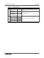
Reading various data files
FXGP/WIN-E has a data file conversion function that converts the data files created by peripheral devices into
Windows format.
Applicable software models:
• SW1PC-FXGP/EE (for AT compatible machine, DOS version)
Converted files:
• Program file (PMC)
• Data register file (DMD, DME, DMG)
• RAM file register (DMF)
• Comment file (COK)
• Sampling trace file (STA)
• Printer title file (PTL)
Unconverted files:
• Comment file (COH)
• Block comment file (COL)
• Diversion ladder circuit file (DAT)
Sequentially select File Open Save As Type and DOS Files (*.pmc) to open a file. When opened, the file will
be automatically converted. Converted data can be stored as the FXGP/WIN-E file described on the
previous page.
1-6
FX Series Programmable Controllers
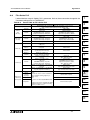
1.4
Introduction 1
Comment Control
FXGP/WIN-E V2.00 or above has enabled storage of device comments in the parameter-set comment area of
the program memory held in the PLC. The number of characters allowed in each comment written to the PLC
is 16 maximum.
2
Comment control using FXGP/WIN-E:
If the FXGP/WIN-E is used, the peripherals can control both types of comments as the device comments;
comments to be controlled by peripheral devices and comments to be written to the PLC.
These device comments can be entered using the input device comment window or comment list program
edit window (refer to Sec. 6.2.13 and Sec. 6.5.5).
Setting comments to be written to the PLC:
The device comments to be controlled by the peripheral devices can be written in the parameter-set comment
area of the program memory in the PLC.
The device comments can be written to the comment area until the comment area is fully loaded (the
comment storage capacity is parameter set). The minimum unit for device comment storage is one comment.
-
Parameter setting (see Sec. 6.8.2)
Device comment entry and specifications (see Sec. 6.2.13)
Setting of comments to be written to the PLC (see Sec. 6.3.9)
Editing and displaying of device comments using device comment/name window (see Sec. 6.5.5)
Programmable controller
•
9
Reading from program file:
A
Writing in program file:
Importing into comment file:
No comment data will be imported into the device comments if the comments are specified as the
comments to be written to the PLC (if the comments are marked with an asterisk * in the device
comment/name window).
•
6
Writing to PLC:
The device comments to be written in the PLC (comments marked with as asterisk *) will be written in the
comment area of the program memory in the PLC.
The device comments to be written to the PLC (comments marked with an asterisk *) will be written to
the program memory, and then stored in the file. All the device comments are stored in the comment file
(.COW).
•
5
8
Before opening a file, a confirmation message will appear and prompt whether the comments in the
program memory should be transferred to the device comment area of the FXGP/WIN-E.
Click “Yes” to transfer the comments to the device comment area of the FXGP/WIN-E. When clicking
“No”, the comments will be loaded to FXGP/WIN-E as program data, therefore, device comment area of
the FXGP/WIN-E will not be subject to change. Even if comments are loaded to FXGP/WIN-E, transfer
the comments into the device comment area later (refer to Sec. 7.8.8).
After clicking “Yes”, the comments are transferred to the device comment area, and regarded as the
comments to be written to the PLC. In addition, the corresponding device numbers displayed in the list
window will be marked with an asterisk *.
•
4
Reading from PLC:
The comments read from the PLC will be transferred to the device comment area of the FXGP/WIN-E. After
transfer, the comments will be set as comments to be written to the PLC, and the corresponding device
numbers shown in the list window will have an asterisk *.
File
•
3
7
Controlling programs including comments:
•
1
Exporting from the comment file:
All the device comments in FXGP/WIN-E will be stored in the file.
1-7
B
C
D
E
FX Series Programmable Controllers
Introduction 1
ROM writer
Data will be read/written to/from the ROM writer in the same way as the PLC.
Exporting and Importing a comment file export:
Only a comment file can be saved (expect) with a different name. An existing comment file can be
read (import) into opened a program file.
Select the comment window, and execute the following operation.
Exporting : [File (F)] → [Export (E)]
Reading : [File (F)] → [Import ( I )]
The comment type can be selected.
If there are comment types which should not be processed in import or export, remove a check
mark in such comment types.
When a program file is saved or read, comment files are handled together. The export and import
operations described above are required only when independent operations for comment files are
required. (Refer to section 6.1.2 and 6.1.4.)
1-8
FX Series Programmable Controllers
2.
Installing FXGP/WIN-E 2
Installing FXGP/WIN-E
This section describes the FXGP-WIN-E installation procedure.
Before installing FXGP/WIN-E, install the necessary system software, such as MS-DOS and MS-Windows.
2.1
1
2
Install Procedure (for Windows 3.1)
1 ) Turn on the power of the PC and start Windows.
3
2 ) Insert the SW0PC- FXGP/WIN system floppy disk (1.44 MB) into the floppy disk drive.
3 ) Click Icon in the Program Manager dialog box.
4 ) Click “Run”.
4
5 ) Click in the Command Line box, and type "A: SETUP EXE". (A= Floppy disk drive name)
6 ) Click the “OK” button.
7 ) Specify the directory where the FXGP/WIN-E should be installed. The default is C:\FXGPWIN
5
8 ) Follow the directions shown on the screen to install FXGP/WIN-E.
6
7
8
9
A
B
C
Uninstallation (for Windows 3.1):
•
To delete this software (application program) from the hard disk, delete all the files from the
installation directory, and FXGPWIN. INI files from the Windows directory using the file manager,
etc. If program files are stored in the directory, be sure to back up the files before deleting this
application program. If the program files are not deleted, it will be deleted together with the
application program.
Initialize of FXGP/WIN-E:
1) FXGP/WIN-E is ended.
2) Delete the FXGP/WIN.INI files from the Windows directory.
3) Restart FXGP/WIN-E.
2-1
D
E
FX Series Programmable Controllers
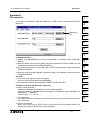
2.2
Installing FXGP/WIN-E 2
Install Procedure (for Windows 95 or after)
To install the FX-PCS/WIN-E component files from the 2 install disks. Note that this software cannot be run
from the install (floppy) disk; this components must be installed onto hard-drive and subsequently run the
software from the drive.
Note:
If the PC had been installed with FX-PCS/WIN-E, please uninstall it. If it is uninstalled before the install, the
FX-PCS/WIN-E may not operate correctly. For uninstall, refer to below.
To install FX-PCS/WIN-E:
1 ) Restart Windows, and do not start-up any other applications.
2 ) Insert the SW0PC-FXGP/WIN-E bellow disk 1 into floppy disk drive.
3 ) Execute “setup32.exe.”
4 ) During the FX-PCS/WIN-E Setup dialog box, click “NEXT” whenever ready thus proceeding to the next
panel.
5 ) If the destination folder need to be changed for the FX-PCS/WIN-E component files, click “Browse”, and
use the browser to locate the appropriate destination.
6 ) Click “NEXT”.
7 ) If the Program folders need to be changed for the FX-PCS/WIN-E, enter the program folder name.
8 ) Click “NEXT” to begin the installation. When the process is complete, a message will follow indicating. He
successful installation of the FX-PCS/WIN-E software.
9 ) Click “OK” to finish to install.
Uninstallation:
It is possible to remove all of the FX-PCS/WIN-E component files installed on your system with
the Install/Uninstall in the Control Panel.
To uninstall FX-PCS/WIN-E:
1 ) Click the “Start Menu”, choose “Setting” > “Control Panel”, and click it.
2 ) Double-click “Add/Remove Programs” icon.
3 ) Select “FX-PCS/WIN-E” in the “Install/Uninstall” tab, and click “Add/Remove”.
4 ) Click “Yes” to begin the uninstall of the FX-PCS/WIN-E component files. When the process
is complete, a FX-PCS/WIN-E is successfully uninstalled from your PC.
2-2
FX Series Programmable Controllers
3.
Main Operation 3
Main Operation
This section describes the main operation of FXGP/WIN-E.
Note that operation methods described in this section are not the special methods used for FXGPWIN-E, but
are the common operation methods used in a Windows environment.
For an inexperienced windows operator, it is recommended that the manual for operating system should be
used in conjunction with this manual.
3.1
Starting method
3.1.1
Starting FXGP/WIN-E for Windows 3.1
1
2
3
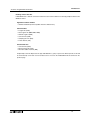
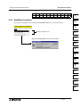
At the completion of install, the MELSEC-F FX application group will be created, and the FXGP/WIN-E start
icon will be stored.
The figure below shows the Windows 3.1 screen.
4
5
6
7
8
9
Double- click on this icon to start FXGP/WIN-E.
The FXGP/WIN-E can activate two or more programs at the same time. For this reason, after starting FXGPWIN-E, if the icon is double- clicked again, another FXGP/WIN-E will be started.
3.1.2
A
Starting FXGP/WIN-E for Windows 95 or After
This software cannot be run from the install (floppy) disk; this components must be installed onto hard-drive
and subsequently run the software from the drive.
B
To start FX-PCS/WIN-E:
•
Click the “Start Menu”, choose “Program” ⇒ “MELSEC-F FX Applications”, and click the name of the
program you want to start.
•
It is possible to also double-click a program icon to begin start-up.
C
D
E
3-1
FX Series Programmable Controllers
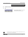
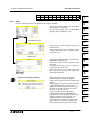
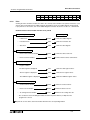
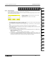
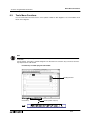
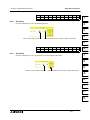
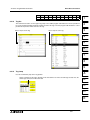
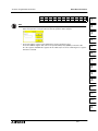
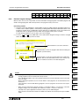
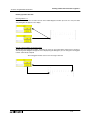
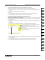
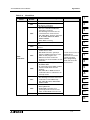
3.2
Main Operation 3
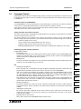
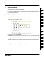
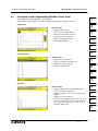
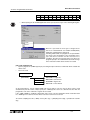
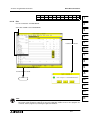
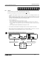
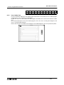
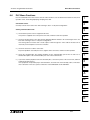
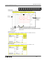
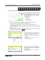
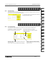
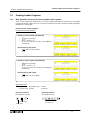
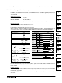
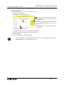
Initial Screen Operation
Read program from PLC
Remote access to PLC
via modem.
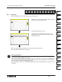
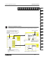
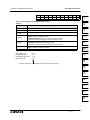
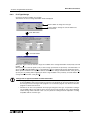
1 ) File menu
New
Use this function to create a new program.
Select the PLC type, and then click the “OK” button.
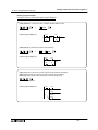
A new file will appear on the display, and data entry is then possible.
Open
Use this function to read out program file from a floppy or hard disk.
-
Select a file type from the Save As Type box, and then select a drive, directory, and file name.
-
From the Save As Type box, select FXGP/WIN-E type program files (*.pmw) or DOS type program
files (*.pmc).
2 ) PLC menu
Program read
This function reads the programs from the PLC connected to the PC.
Before reading the programs, be sure to connect the PC to the PLC using the appropriate cabling and
interface unit.
Ports
Use this function to select an RS-232 port from the PC in order to connect the PLC or ROM to the PC.
3 ) Remote
See.Sec.9.3 "Functions on Remote Menu"
3-2
FX Series Programmable Controllers
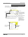
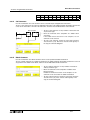
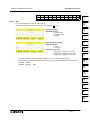
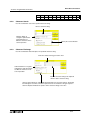
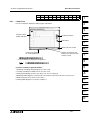
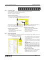
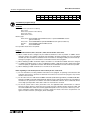
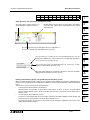
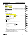
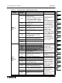
3.3
Main Operation 3
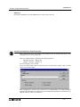
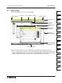
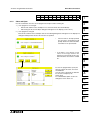
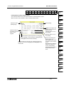
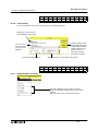
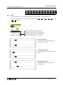
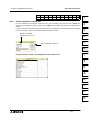
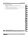
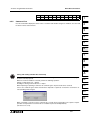
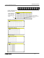
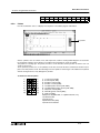
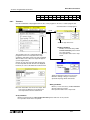
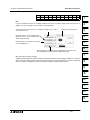
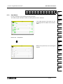
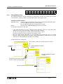
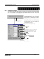
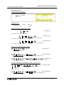
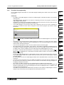
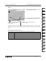
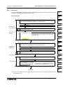
Main screens
1
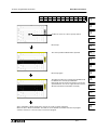
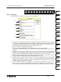
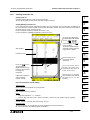
This section describes the main screens of FXGP/WIN-E.
Control menu box *1 Tool menu
Title of window
Tool bar
Minimize button *1
2
Maximize button *1
3
SFC program
edit window
List program edit
window
Ladder program
edit window
FXGP/WIN-E
application window
4
5
6
7
Status bar (Displays
the edit mode, step
number, etc.)
8
9
Function key guidance
The Minimize button shrinks the size of the ladder program edit window, list program edit window, etc.
*1: When either Windows 95, Windows 98, Windows Millennium Edition, WindowsNT 4.0 Workstation,
Windows 2000 or Windows XP are used, the FX icon will be displayed in place of the control menu box. In
addition, the Minimize, Maximum, and Close buttons are different from those shown above.
A
B
C
D
E
3-3
FX Series Programmable Controllers
3.4
Main Operation 3
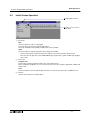
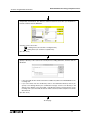
Terminating method (Exit)
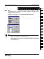
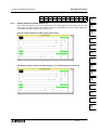
There are two program termination methods for FXGP/WIN-E.
For either method, if there is a non-stored file, the following confirmation dialog box will appear on the display:
1 ) Sequentially select File and then Exit.
2 ) Click in the control menu box of the application window, and then select Close.
When either Windows 95, Windows 98, Windows Millennium Edition, Windows NT 4.0 Workstation,
Windows 2000 or Windows XP are used, click on the FX icon at the upper left corner of the box, or the
Close button (×) at the upper right corner of the box.
The FXGP/WIN-E can open two or more the application windows.
Note that the Exit command is valid only for the application window currently active. If two or more
programs are activated, sequentially end the programs by simultaneously activating the application
windows.
3-4
FX Series Programmable Controllers
4.
Work Windows and their Functions 4
Work Windows and their Functions
FXGP/WIN-E has six work windows that ensures efficient programming, thus, various form of operations can
be performed using such windows.
To create a program, open the appropriate window, then create the program. Monitoring is also possible.
Various function that can be executed in each window will be shown in the menu bar. The menu bar, therefore,
is optimized for each work window.
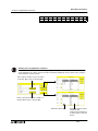
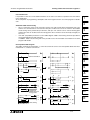
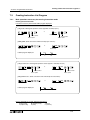
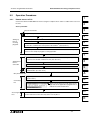
Construction and Types of Windows
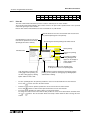
4.1.1
Construction of windows and relation between windows
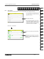
The windows of FXGP/WIN-E can be divided into six types as shown below.
Each window group can display two or more windows at the same time, and the active window can be
switched in each group to proceed to the next Window. Minimize the unused windows to keep it on screen
until you use it. The minimized window looks like an icon.
Programming window group
Comment window group
Ladder
Instruction
SFC
Inner Ladder
Device
Device
Block
Coil
Register window
4
5
6
Name
Comment
Comment
Comment
7
Device list window group
Contact / Coil
Device used
TC setting
Device monitor window
2
3
4.1
View
View
View
View
1
8
list
list
list
9
Sampling trace window
A
B
C
D
E
4-1
FX Series Programmable Controllers
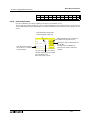
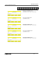
4.1.2
Work Windows and their Functions 4
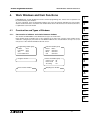
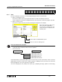
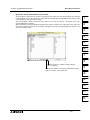
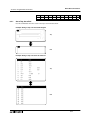
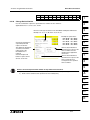
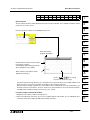
Handling of opened FXGP/WIN-E softwares at a time
In the FXGP/WIN-E, up two or more program files can open at a time.
When either of the following operations is executed while the FXGP/WIN-E has been already started up and a
program file is open, the second FXGP/WIN-E program can be started up.
•
Started up a FXGP/WIN-E.
•
Select [File (F)] → [New (N)].
•
Select [File (F)] → [Open (O)].
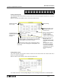
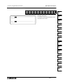
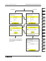
Each of opened FXGP/WIN-E software at a time acts as an independent program file when changing over the
active window. Or such programs can be displayed at a time when the window size is adjusted as shown in
the figure below.
Among different application windows, programs and comments can be shared by using the cut & paste
operation.
Application window 1
Application window 2
4-2
FX Series Programmable Controllers
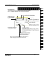
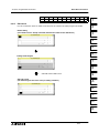
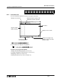
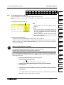
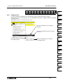
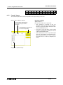
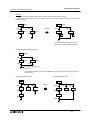
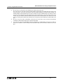
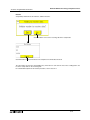
4.1.3
Work Windows and their Functions 4
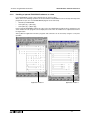
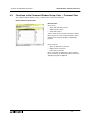
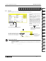
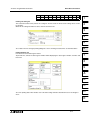
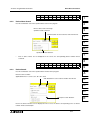
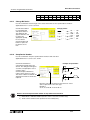
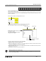
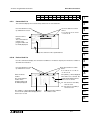
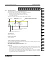
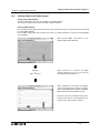
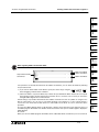
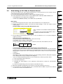
Split window
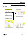
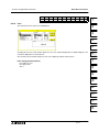
The ladder program edit, list program edit, comment and register windows can be split.
Split the window into two; upper and lower windows.These windows can display the respective sections.
1
Example of a ladder program edit window (in monitoring mode)
2
3
4
5
Move the split handle using the mouse
to the split position.
Adjust the split position to adjust the
upper and lower areas.
6
7
8
Use the scroll bar of each window to
select the section to be displayed.
9
A
B
C
D
E
After you edit a ladder diagram in a split window, store the changed data, and then move to another
window.
4-3
FX Series Programmable Controllers
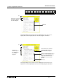
4.1.4
Work Windows and their Functions 4
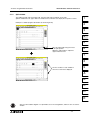
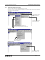
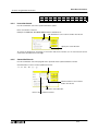
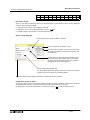
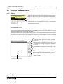
Selecting a window from tool menu
Select every work window of the FXGP/WIN-E from the menu bar.
Because the menu bar is always optimized according to the contents of work, some menu items cannot be
selected on the active work window.
View menu
Programming window
group
(Refer to Section 4.2.)
Comment window group
(Refer to Section 4.3.)
Register window (Refer to Section 4.4.)
Device list window group (Refer to Section 4.5.)
PLC menu
Sampling trace window
(Refer to Section 4.6.)
Monitor/Test menu
Device monitor window
(Refer to Section 4.6.)
4-4
FX Series Programmable Controllers
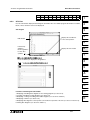
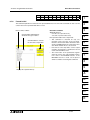
4.2
Work Windows and their Functions 4
Functions of the Programming Window Group: View
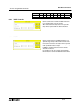
1
The programming windows displays or edits programs.
When a ladder or SFC program edit window is displayed, monitor the operation of the PLC.
Ladder View
2
Main functions:
•
Displays ladder circuits.
•
Creates or edits ladder circuits.
•
Monitors the operation of the PLC.
•
Displays or stores comments.
•
Writes data during run mode.
•
Prints ladder diagrams.
3
4
5
6
Instruction View
Main functions:
•
Displays the instruction list.
•
Creates or ediats the instruction list.
•
Displays or stores comments.
•
Prints the instruction list.
7
8
9
A
SFC View
B
Main functions:
•
Displays ladder circuits using the SFC format.
•
Creates or edits SFC diagrams.
•
Monitors operation of the PLC using the SFC
diagram.
•
Displays or stores comments.
•
Prints the SFC diagrams Execute View (V) and
then Inner Ladder View (A) in the SFC program
e dit w ind ow to dis play t he in ne r sta t e o r
transition ladder circuit.
C
D
E
4-5
FX Series Programmable Controllers
4.3
Work Windows and their Functions 4
Functions of the Comment Window Group: View → Comment View
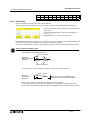
The comment windows displays, stores, or edits the device names and comments.
Device comment / Device name
Main functions:
Device name
•
Stores and edits device names.
•
Displays device names.
•
Prints device names.
A device name can be stored for each device number.
Device names are can be used instead of the device
numbers when creating a program or displaying a
program.
Device comment
•
Stores or edits device comments.
•
Displays device comments.
•
Prints device comments.
Device comments are added to the device numbers.
Devise comments are attached to all devices when the
appropriate program is displayed.
4-6
FX Series Programmable Controllers
Work Windows and their Functions 4
Block comment
1
Main functions:
•
Stores and edits block comments.
•
Displays block comment.
A block comment can be stored for each circuit block.
2
3
4
5
Coil comment
6
Main functions:
• Stores or edits coil comments.
• Displays coil comments.
A coil comments can be stored for each OUT, SET,
RST and applied instruction.
7
8
9
A
B
C
D
E
4-7
FX Series Programmable Controllers
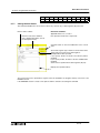
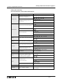
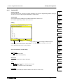
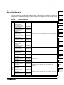
4.4
Work Windows and their Functions 4
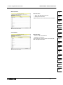
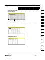
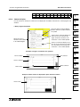
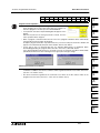
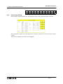
Functions of the Register Window: View → Register View
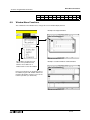
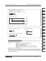
The register window displays data or file registers read from the PLC. Also, the register window edits data or
file registers. On the completion of data editing, FXGP/WIN-E writes edited data to the PLC.
Examples of displayed windows
16-bit table type
Main functions:
•
Displays or edits data or file registers read from the
PLC.
•
Creates or edits data or file registers, and writes
the created or edited data to the PLC.
•
Prints register data informat.
32-bit line type
There are two or more optional register display
methods. If a different display method is specified, the
displayed screen may differ from the example shown
in the left figure.
4-8
FX Series Programmable Controllers
4.5
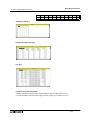
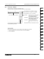
Work Windows and their Functions 4
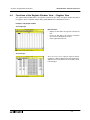
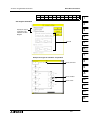
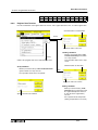
Functions of the Device List Window Group: View →
The device list windows search for devices (X, Y, M, S, T, C, D, P, I, N, V, Z, etc.) incorporated in to the PLC
and display the devices that are used in programs.
Contact/Coil list
1
2
Main functions:
•
Displays step numbers to clarify where the
contacts and the output coils of the specified
devices are used in the program.
•
Displays device names and comments.
•
Searches the program for specified contact or
output symbols.
•
Prints the list.
3
4
5
6
Device used list
Main functions:
•
Displays whether the specified contacts and
output coils are used in the program.
(Specify a device, and conditions of 24 contacts
and coils started from the specified device will be
displayed.)
•
Prints the list.
7
8
9
A
TC setting list
B
Main functions:
•
•
Displays the timer or counter setting values written
in the program.
(Specify a device, and the setting values of 24
timers and counters started from the specified
device will be displayed.)
Prints the list.
C
D
E
4-9
FX Series Programmable Controllers
4.6
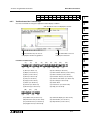
Work Windows and their Functions 4
Functions of the Sampling Trace Window Group: PLC → Sampling
Trace
The sampling trace windows to display the device on/ off operation and data change detected by the sampling
trace function. A time chart will be used as the display format.
Example of displayed window
Main functions:
•
Displays the operation history of the specified
device.
The on/ off operation of the bit devices and the
numeric values of the word devices will be
displayed.
•
Displays the detailed operation of the bar position.
•
Prints the sampling trace result.
4-10
FX Series Programmable Controllers
4.7
Work Windows and their Functions 4
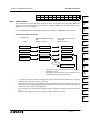
Functions of Device Monitor Window: Monitor/Test →
1
Use the device monitor window to monitor the operation of the PLC devices on the screen.
Entry device monitor
2
Main functions:
•
Monitors operation of the input relay (X), output
relay (Y), auxiliary relay (M), state (S), timer (T),
counter (C), data register (D), and index registers
(V and Z).
•
Up to 48 device numbers can be stored.
•
The data register display type can be selected
from the following types: 16/32 bit, binar y,
decimal, hexadecimal, ASCII, and floating point
display types.
3
4
5
6
7
8
9
A
B
C
D
E
4-11
FX Series Programmable Controllers
Work Windows and their Functions 4
MEMO
4-12
FX Series Programmable Controllers
5.
Guidance of Main Operations 5
Guidance of Main Operations
This section classifies, among explanation of operation methods and menu commands of the FXGP/WIN-E,
functions and operations often used by keywords, and summarizes the execution method for each item.
The contents described here may require a different operation or prerequisite depending on the actual
operation status. Refer to this section as basic operations for the FXGP/WIN-E software.
5.1
Startup/Edit/window display
1
2
3
[Starting up the FXGP/WIN-E]
Choose the "FXGP/WIN-E" icon in the "MELSEC-F FX application" in the “Start Menu → program”.
(Refer to Section 3.1)
[Starting up two or more FXGP/WIN-E programs]
While one or two FXGP/WIN-E programs are running, click again the "FXGP/WIN-E" icon or execute
[File (F)] → [New (N)] → [Open (O)]. (Refer to Sections 4.1.2 and 6.1.1.)
[Terminating the FXGP/WIN-E]
4
5
Choose [File (F)] → [Exit (X)]. (Refer to Sections 3.4 and 6.1.12.)
[Changing the display size of a ladder circuit or list on the edit window]
Choose [View (V)] → [Zoom (Z)]. Or [Option (O)] → [Font (F)]. (Refer to Sections 6.5.14 and 6.8.12.)
6
[Displaying the edit window in the split status]
Adjust the split handle provided at the bottom of the edit window in the vertical direction to split the
screen. (Refer to Section 4.1.3.)
7
[Editing two or more programs at a time]
Start up two or more FXGP/WIN-E applications, then edit them while changing over the application
window. Or edit them while collating them displayed side by side on the screen. (Refer to Section 4.1.2.)
8
[Changing over two or more windows efficiently]
In the Windows, use the key combinations "[GRPH] + [TAB]", "[GRPH] + [ESC]" and "[CTRL] + [TAB]" to
change over the windows and change over the active window efficiently. (Refer to the Windows manual.)
9
[Changing the edit window type]
A
Choose the edit window type in [View (V)] menu. (Refer to Section 6.5.)
B
C
D
E
5-1
FX Series Programmable Controllers
5.2
Guidance of Main Operations 5
Program
[Creating a new program]
Choose [File (F)] → [New (N)]. (Refer to Section 6.1.1.)
[All-clearing a program]
Choose [Tools (T)] → [All clear (A)]. (Refer to Section 6.3.6.)
[Transferring a program to the PLC]
Choose [PLC (P)] → [Transfer (T)]. (Refer to Section 6.6.1.)
[Reading a program from a file]
Choose [File (F)] → [Open (O)]. (Refer to Section 6.1.2.)
[Saving a program to a file]
Choose [File (F)] → [Save (S)] (or [Save as (A)]). (Refer to Sections 6.1.4 and 6.1.5.)
[Checking for errors in a program]
Choose [Option (O)] → [Program check (C)]. (Refer to Section 6.8.1.)
[Printing a program]
Display the window of item to be printed, then choose [File (F)] → [Print (P)]. When printing two or more
items at a time, execute [Print All (T)]. (Refer to Sections 6.1.6 and 6.1.7.)
[Setting/changing the program memory capacity]
Choose [Option (O)] → [Parameter Settings (P)]. (Refer to Section 6.8.2.)
[Overwriting NOP instructions to a program]
Choose [Edit (E)] → [NOP overwrite (W)] from the list program edit window. (Refer to Section 6.2.9.)
[Inserting NOP instructions into a program]
Choose [Edit (E)] → [NOP insert (S)] from the list program edit window. (Refer to Section 6.2.10.)
[Removing NOP instructions from a program]
Choose [Edit (E)] → [NOP remove (E)] from the list program edit window. (Refer to Section 6.2.11.)
[Displaying the program on the specified step]
Choose [Search (S)] → [Go to step (O)]. (Refer to Section 6.4.6.)
[Searching and displaying the specified device number]
Choose [Search (S)] → [Device name search (D)] (or [Contact/Coil search (O)]). (Refer to Sections 6.4.3
and 6.4.5.)
[Searching and displaying the specified the instruction, Contact or Coil]
Choose [Search (S)] → [Instruction search (I)] (or [Contact/Coil Search (O)]). (Refer to Sections 6.4.4
and 6.4.5.)
[Displaying program on the set position]
Select [Search (S)] → [Tag Set (G)] to store an arbitrary program position as the tag position. Select [Tag
jump (J)] to display the program portion in the stored tag position. (Refer to Sections 6.4.13 and 6.4.14.)
[Replacing a device No.]
Choose [Search (S)] → [Replace Device (V)]. (Refer to Section 6.4.10.)
[Exchanging an a-/b-contact]
Choose [Search (S)] → [Change AB Contact (A)]. (Refer to Section 6.4.11.)
[Exchanging a device Number]
Choose [Search (S)] → [Exchange Device (E)]. (Refer to Section 6.4.12.)
5-2
FX Series Programmable Controllers
5.3
Guidance of Main Operations 5
Ladder circuit
1
[Displaying the ladder program edit window]
Choose [View (V)] → [Ladder view (L)]. (Refer to Section 6.5.1.)
[Editing a ladder circuit]
Pressing a function key or choosing symbol from [Tools (T)] menu on the ladder program edit window.
(Refer to Sections 6.3 and 7.2.)
2
[Editing a ladder circuit symbol by an instruction word program]
Put the cursor in a symbol input position on the ladder program edit window, then input a instruction word
from the keyboard in the same way as inputs to a list. (Refer to Section 7.2.2.)
3
[Printing a ladder format]
Choose [File (F)] → [Print (P)] from the ladder program edit window. When printing two or more items at
a time, choose [Print All (T)]. (Refer to Sections 6.1.6 and 6.1.7.)
[Converting a ladder circuit and handling a ladder error]
Pressing the [f4] or choosing [Tools (T)] → [Convert (C)] from the ladder program edit window. (Refer to
Sections 6.3.7 and 7.2.3.)
When a ladder error occurs, modify the program to establish the ladder circuit. When destroying the
contents of change and terminating the conversion mode, first, open the list program edit window, close
the ladder program edit window once. (Refer to Sections 6.2.6, 6.2.7 and 7.2.3.)
4
5
6
[Specifying a range assignment by program circuit blocks]
Put the cursor in the range assignment start position, "[SHIFT] + [↑]/[↓]", "[SHIFT] + mouse dragging" or
"[Edit (E)] → [Block select (B)] → [Up (U)]/[Down (D)]" after convert circuit a ladder. (Refer to Sections
6.2.8 and 7.2.4.)
[Specifying a range assignment by ladder symbol]
Put the cursor in the range assignment start position, then drag the mouse to the range assignment end
position. (Refer to Section 7.2.4.)
[Copying and pasting a ladder circuit]
Put the cursor on a symbol to be copied or specify a range to be copied, then choose [Edit (E)] → [Copy
(C)] (or [Paste (P)]). (Refer to Sections 6.2.8 and 7.2.4.)
[Inserting a blank line for new ladder circuit]
Put the cursor in an insertion position, then choose [Edit (E)] → [Line insert (I)]. (Refer to Section 6.2.7.)
7
8
9
A
[Deleting the ladder circuit block]
Put the cursor in a deletion position, select a ladder circuit block to be deleted by operating "[SHIFT] +
[↑]/[↓]", "[SHIFT] + mouse dragging" or "[Edit (E)] → [Select Block (B)]", then choose [Edit (E)] → [Cut
(T)] (, [Delete (D)] or [DEL]). (Refer to Sections 6.2.8 and 7.2.4.)
B
[Deleting a Instruction symbol]
Put the cursor on a symbol to be deleted, then choose [Edit (E)] → [Cut (T)] (or [Delete (D)]). Or the
[DEL] and [BS] keys are available also. (Refer to Sections 6.2.2, 6.2.5 and 7.2.4.)
C
[Switching over the overwrite/insert mode for making program]
Press the [INS] key on the ladder program edit window. The input characteristics are displayed at the
lower right corner of the screen. (Refer to Section 7.2.4.)
D
[Deleting a vertical line symbol]
Put the cursor at the upper right corner of a vertical line, then pressing "[SHIFT] + [f8]", choosing "[Tools
(T)] → [Line (W)]" or "[| DEL] on the tool pallet". (Refer to Sections 6.3.4, 6.5.8 and 7.2.4.)
[Inputting the pointer "P" or "I"]
Put the cursor on the left side of a bus bar (that is, at the left edge of the screen), then press the [P] or [I]
key. (Refer to Section 7.2.1.)
5-3
E
FX Series Programmable Controllers
Guidance of Main Operations 5
[Inputting horizontal lines/vertical lines continuously]
[GRPH] + [→]/[←]: Inputs horizontal lines. (Refer to Section 7.2.1.)
[GRPH] + [↑]/[↓]: Inputs vertical lines. (Refer to Section 7.2.1.)
[Deleting horizontal lines/vertical lines continuously]
[CTRL] + [GRPH] + [→]/[←]: Deletes horizontal lines. (Refer to Section 7.2.4.)
[CTRL] + [GRPH] + [↑]/[↓]: Deletes vertical lines. (Refer to Section 7.2.4.)
[Destroying the contents of ladder circuit edition]
Choose [Edit (E)] → [Edit cancel (E)], before converting ladder program. (Refer to Section 6.2.17.)
5.4
List
[Displaying the list program edit window]
Choose [View (V)] → [Instruction list view (I)]. (Refer to Section 6.5.2.)
[Editing a list]
Input an instruction word directly on the list program edit window. Or using a function key or [Tools (T)] →
[Instruction (I)]. (Refer to Sections 6.3.5 and 7.3.2.)
[Printing a list]
Choose [File (F)] → [Print (P)] on the list program edit window. When printing two or more items at a time,
execute [Print All (T)]. (Refer to Sections 6.1.6 and 6.1.7.)
5.5
SFC
[Displaying the SFC program edit window]
Choose [View (V)] → [SFC view (S)]. (Refer to Section 6.5.3.)
[Editing an SFC diagram]
Using function keys on the SFC program edit window. (Refer to Sections 6.3 and 8.2.)
[Converting an SFC program]
Press the function key [f4] or choose [Tools (T)] → [Convert (C)] on the SFC program edit window. (Refer
to Sections 6.3.7 and 8.2.3.)
[Printing an SFC diagram]
Choose [File (F)] → [Print (P)] on the SFC program edit window. When printing two or more items at a
time, choose [Print All (T)]. (Refer to Sections 6.1.6 and 6.1.7.)
5.6
Instruction input
[Inputting a program in an device name comment]
In programming, a device No. such as X0 can be input in an device name comment. During the input
operation, input to the X0 an device name registered to the X0 while adding the "'" symbol on either side.
Example: LS1; "LS1" is an example of device name registered to the X0. (Refer to Sections 7.2.1 and
7.3.1.)
[Inputting an applied instruction by selecting it from a list]
On the ladder program edit window, choose [Tools (T)] → [Function (F)] → [Reference (R)].
In a list program edit window, choose [Tools (T)] → [Instruction (I)].
(Refer to Sections 6.3.3 and 6.3.5.)
5-4
FX Series Programmable Controllers
5.7
Guidance of Main Operations 5
PLC
[Selecting the PLC type]
When creating a new file, when reading (up-loading) a program from the PLC, or when reading a file in
the DOS version, the PLC type setting dialog box is displayed upon necessity. (Refer to Sections 6.1.1,
6.1.2 and 6.6.1.)
[Changing the PLC type]
1
2
Choose [Options (O)] → [PLC type change (H)]. (Refer to Section 6.8.9.)
3
[Writing (down-loading) a program to the PLC]
Choose [PLC (P)] → [Transfers (T)]. (Refer to Section 6.6.1.)
[Writing (down-loading) a register (data register/file register/RAM file register) to the PLC]
Choose [PLC (P)] → [Register data transfers (R)]. (Refer to Section 6.6.2.)
4
[Clearing the program, word device or bit devices in the PLC]
Choose [PLC (P)] → [PLC memory Clear (P)]. (Refer to Section 6.6.3.)
5
[Checking error status in the PLC]
Choose [PLC (P)] → [PLC diagnosis (D)]. (Refer to Section 6.6.8.)
6
[Checking the PLC operation time]
Choose [PLC (P)] → [PLC diagnosis (D)]. (Refer to Section 6.6.8.)
[Registering/changing the password for password protection in/to the PLC]
7
Choose [PLC (P)] → [PLC keyboard current, delete (K)]. (Refer to Section 6.6.5.)
[Changing the setting value of a timer/counter in the PLC]
Choose [Monitor/Test (M)] → [Change the setting value (C)]. (Refer to Section 6.7.7.)
Select one target device on the ladder program monitor window, then click the right button of the mouse
to display the shortcut menu. (Refer to Section 6.7.1.)
[Changing the current value of a timer/counter/register in the PLC]
8
9
Choose [Monitor/Test (M)] → [Change the current values (C)]. (Refer to Section 6.7.8.)
Select one target device on the ladder program monitor window, then click the right button of the mouse
to (switching) display the shortcut menu. (Refer to Section 6.7.1.)
A
[Forcing the output to ON/OFF]
Choose [Monitor/Test (M)] → [Force Y Output (F)]. (Refer to Section 6.7.5.)
[Forcing a device to set/reset]
B
Choose [Monitor/Test (M)] → [Force ON/OFF (R)]. (Refer to Section 6.7.6.)
Select one target device on the ladder program monitor window, then click the right button of the mouse
to display the shortcut menu. (Refer to Section 6.7.1.)
[Changing a program in RUN mode]
Change only one ladder circuit block on the ladder program edit window, then press "[SHIFT] + [f4]" or
choose "[Tools (T)] → [Runtime program changes (U)]" without converting the ladder circuit block. (Refer
to Section 6.6.6.)
C
D
[RUN/STOP the FX1S/FX1N/FX2N/FX1NC/FX2NC PLC]
Choose [PLC (P)] → [Remote RUN/STOP (O)]. (Refer to Section 6.6.7.)
E
5-5
FX Series Programmable Controllers
5.8
Guidance of Main Operations 5
Monitor
[Monitoring a ladder program]
Choose [PLC (P)] → [Start monitor (M)] on the ladder program edit window. (Refer to Section 6.7.1.)
[Monitoring an SFC diagram]
Choose [PLC (P)] → [Start monitor (M)] on the SFC program edit window. (Refer to Section 6.7.1.)
[Monitoring device status]
Choose [Monitor/Test (M)] → [Entry device monitor (cursor) (E)]. (Refer to Section 6.7.4.)
Select one target device on the ladder program monitor window, then click the right button of the mouse
to display the shortcut menu.
[Monitoring the value of the data register, timer or counter]
Choose [Monitor/Test (M)] → [Entry device monitor (T, C, D device) (T)]. (Refer to Section 6.7.4.)
Select one target device on the ladder circuit monitor screen, then click the right button of the mouse to
display the shortcut menu.
[Monitoring the SFC program automatically]
Choose [Monitor/Test (M)] → [Start auto monitor (A)] on the SFC program edit window.
(Refer to Section 6.7.3.)
[Stopping the monitor]
Choose [Monitor/Test (M)] → [Stop Monitor]. (Refer to Section 6.7.2.)
[Saving and reading the registered contents of the Entry device monitor]
Choose [File (F)] → [Export (E)] (or [Import (I)]) on the device monitor window. (Refer to Section 6.7.4.)
5.9
Comment
[Displaying a program with comments]
While the ladder/list/SFC program edit window is displayed, choose [View (V)] → [Comment display (M)].
(Refer to Section 6.5.12.)
[Printing a list of the device names or device comments]
Choose [View (V)] → [Comment view (C)] → [Device comment/Device name (D)], and display the device
name/device comment edit window.
Then choose [File (F)] → [Print (P)] (or [Print All (T)] for printing out two or more items at a time). (Refer
to Sections 6.1.6, 6.1.7 and 6.5.5.)
[Printing a program with a comment]
Choose [File (F)] → [Print (P)] (or [Print All (T)] for printing out two or more items at a time), then specify
comment type to be printed on the print setting dialog box. (Refer to Sections 6.1.6 and 6.1.7.)
[Registering an device name to a device]
While the ladder or list program edit window, etc. is displayed, choose [Edit (E)] → [Device name (N)]. Or
choose [View (V)] → [Comment view (C)], then input device name at a time. (Refer to Sections 6.2.12
and 6.5.5.)
[Registering a device comment]
While the ladder program list program edit window, etc. is displayed, choose [Edit (E)] → [Device
comment (V)]. Or choose [View (V)] → [Comment view (C)], then input device comments at a time.
(Refer to Sections 6.2.13 and 6.5.5.)
[Registering a coil comment]
While the ladder program edit window is displayed, put the cursor on a coil for which a comment is to be
registered, then choose [Edit (E)] → [Coil Comment (O)]. (Refer to Section 6.2.14.)
5-6
FX Series Programmable Controllers
Guidance of Main Operations 5
[Registering a block comment]
While the ladder program edit window is displayed, put the cursor on a ladder circuit block for which a
comment is to be registered, then choose [Edit (E)] → [Block comment (M)]. (Refer to Section 6.2.15.)
1
[Inputting a device comment efficiently while making program]
Choose [Options (O)] → [Preferences (I)], then add check mark to “Executes consecutively during
instruction input.” By this setting, the dialog box for device comment input is displayed after instruction
was inputted. (Refer to Section 6.8.10.)
2
[Clearing comments]
Choose [View (V)] → [Comment view (C)] to display the device name/device comment edit window.
Then choose [Tools (T) → [All clear (A)] and then select the cleared comments type. (Refer to Sections
6.3.6 and 6.5.5.)
3
[Using an existing comment file]
4
To export a comment file, choose [File (F)] → [Export (E)] on the comment edit window. To import the
existence comment file, choose [File (F)] → [Import (I)] on the comment window. (Refer to Section 6.5.5.)
5.10
5
Printer
[Printing (active window)]
While an edit window to be printed is displayed, choose [File (F)] → [Print (P)]. (Refer to Section 6.1.6.)
6
[Printing (two or more windows)]
While an arbitrary edit window is displayed, choose [File (F)] → [Print All (T)]. (Refer to Section 6.1.7.)
[Previewing the print result]
While an edit window to be previewed is displayed, choose [File (F)] → [Print preview (V)]. Or click
“Preview (V)” button on the print setting dialog box. (Refer to Sections 6.1.9 and 6.1.6.)
[Selecting print items]
Choose [File (F)] → [Print (P)] (or [Print All (T)] for printing out two or more items at a time), then specify
an item (or items) to be printed. (Refer to Sections 6.1.6 and 6.1.7.)
[Limiting the print range]
Choose [File (F)] → [Print (P)] (or [Print All (T)] for printing out two or more items at a time), then specify
the range to be printed. (Refer to Sections 6.1.6 and 6.1.7.)
7
8
9
[Attaching the front cover or the parameter setting]
A
Choose [File (F)] → [Print (P)] (or [Print All (T)] for printing out two or more items at a time), then add
check mark to check box of the “Title (I)” or “Parameter settings list (E).“ (Refer to Sections 6.1.6 and
6.1.7.)
B
[Changing the print size]
Choose [File (F)] → [Print (P)] (or [Print All (T)] for printing out two or more items at a time), then choose
size from “Scale” pull down menu. (Refer to Sections 6.1.6 and 6.1.7.)
C
[Setting the margin, header and footer of the print paper]
Choose [File (F)] → [Paper setup (G)]. (Refer to Section 6.1.8.)
D
[Setting the paper size, direction and paper feed position]
Choose [File (F)] → [Printer setup (G)]. (Refer to Section 6.1.10.)
[Printing according to the paper size]
Choose “Auto” from “Scale” pull down menu on the print setting dialog box. By this setting, printing is
executed according to the lateral width of the specified paper. (Refer to Section 6.1.6.)
5-7
E
FX Series Programmable Controllers
5.11
Guidance of Main Operations 5
PC
[Connecting the PC to the PLC]
As the RS-232C/RS-422 conversion interface, use the FX-232AWC or FX-232AW. The connection cable
depends on the PC and connected PLC model; Refer to the corresponding explanation item. (Refer to
Section 1.2.3.)
[Connecting the PC to the ROM writer]
Connect the COM port (RS-232C) connector in the PC to the RS-232C port in the ROM writer with a
cable FX-232CAB-1. (Refer to Sections 1.2.3 and 6.8.11.)
[Selecting an RS-232C port in the PC]
Choose [PLC (P)] → [Ports (S)]. (Refer to Section 6.6.10.)
[Changing the password registered with a program in the PC]
Choose [Options (O)] → [Entry Code Setting (Y)]. (Refer to Section 6.8.3.)
5.12
Data compatibility and conversion
[Reading data in the DOS version]
Choose [File (F)] → [Open (O)], then select “*.PMC” from “File Type (T)” pull down menu. (Refer to
Sections 6.1.2 and 3.1.3.)
[Saving data in a DOS format file]
Choose [File (F)] → [Save As (A)], then select “*.PMC” from “File Type (T)” pull down menu. (Refer to
Sections 6.1.2 and 3.1.1.)
[Handling comments in the program memory]
Comments can be transferred to device comments. In this case, comments to be written to the PLC need
to set. (Refer to Section 1.6.)
5.13
Telephone line connection
[Downloading, uploading and monitoring with the PLC through the telephone line]
Use the remote maintenance of the PLC. (Refer to Section 9.1.1.)
[Sending and receiving data through the telephone line]
Use the file transfer function. (Refer to Section 9.1.2.)
[Connecting to the telephone line]
For remote maintenance refer to Section 9.2.1.
For file transfer, refer to Section 9.2.2.
[Modem setting]
Choose [Remote (R)] → [Environment (E)] → [Modem (M)]. (Refer to Section 9.3.4.)
[Connecting the telephone line]
Choose [Remote (R)] → [Connect (C)]. (Refer to Section 9.3.1.)
[Setting the FX1S/FX1N/FX2N/FX2NC PLC for connection to the telephone line]
Set the PLC for remote maintenance. (Refer to Section 9.4.)
Note
The remote maintenance cannot be supported on the following operating systems.
Windows NT 4.0 Workstation
Windows 2000
Windows XP
5-8
FX Series Programmable Controllers
5.14
Guidance of Main Operations 5
Others
[Open recent file]
Displays the history of the file opened in the past. Select the arbitrary file from the displayed history and
clicking. The file that has been opened in the past can be opened again.
(Refer to Paragraphs 6.1.11 and 3.1.1.)
1
[Tracing the device status in PLC]
2
The FX/FX2C/FX2N/FX2NC PLC is equipped with the sampling trace function which traces the device
status in the PLC. For the condition settings and result display of the sampling trace function, choose
[PLC (P)] → [Sampling trace (M)]. (Refer to Paragraph 6.6.9.)
3
[Downloading the data register value to PLC from PC]
Choose [PLC (P)] → [Register data transfers (R)] to download the value of a data register and file
register created in the PC to the PLC. Because a file register is stored in the program memory, it can be
transferred also by [Write (W)]. (Refer to Paragraphs 6.5.6 and 6.6.2.)
[Setting the parameter]
Choose [Options (O)] → [Parameter setting (P)] to set parameters including the area to hold devices in
the program step/file register area in the PLC. (Refer to Paragraph 6.8.2.)
4
5
[Setting the file register area]
6
Choose [Options (O)] → [Parameter Setting (P)]. (Refer to Paragraph 6.8.2.)
[Specifying a display font]
Choose [Options (O)] → [Font (F)]. Specify "MS Sans Serif" usually because something may be wrong
with the display if an alphabetic font is selected. (Refer to Paragraph 6.8.12.)
7
[Using help file]
Select the [Help (H)] menu or pressing the function key (f1) to display help file. (Refer to Paragraph 6.10.)
[Checking the version]
8
Choose [Help (H)] → [About SW0PC-FXGP/WIN-E (A)]. (Refer to Paragraph 6.10.)
9
A
B
C
D
E
5-9
Guidance of Main Operations 5
FX Series Programmable Controllers
MEMO
5-10
FX Series Programmable Controllers
6.
Menu Bar Commands 6
Menu Bar Commands
This chapter describes the functions of the commands shown on each of the pull-down menus.
The commands shown on the pull-down menu depend on the edit window currently active and the operation
status. In addition, the function of the same command may be changed when the active window is switched.
1
2
Description of this section
This section describes all the commands of each pull-down menu.
The command-valid windows and the operation status will be shown first for each command.
3
Showing valid commands:
OPN
L/V
✓
L/M
I/V
S/V
✓
✓
S/M
C/V
R/V
D/L
✓
✓
✓
4
D/M SMP
✓
✓
5
Window or operation status
Check mark showing valid command
6
OPN : Opening
L/ V : Ladder View
L/ M : Ladder Monitor
I/ V : Instruction View
S/ V : SFC View
S/ M : SFC Monitor
C/ V : Comment View
R/ V : Register View
D/ L : Contact/Coil list, Device used list, TC setting list
D/ M : Device Monitor
SMP : Sampling trace
7
8
9
A
B
C
D
E
6-1
Menu Bar Commands 6
FX Series Programmable Controllers
6.1
File Menu Functions
6.1.1
New
OPN
L/V
L/M
I/V
S/V
S/M
C/V
R/V
D/L
✓
✓
✓
✓
✓
✓
✓
✓
✓
D/M SMP
✓
✓
Use this command to create new program files.
•
•
Choose “File” and then “New”. The PLC Type Setting
dialog box will appear on the display.
•
Select a PLC type, and then click the “OK” button.
Commands, internal devices, and number of steps usable for programming depend on the PLC
type specified in the PLC Type Setting dialog box.
6-2
FX Series Programmable Controllers
6.1.2
Menu Bar Commands 6
OPN
L/V
L/M
I/V
S/V
S/M
C/V
R/V
D/L
✓
✓
✓
✓
✓
✓
✓
✓
✓
D/M SMP
✓
✓
1
Open
2
Use this command to read out a program file from a floppy or hard disk.
•
Choose “File” and then “Open”. The Open dialog
box will appear on the display.
•
From the File Type box, select the FXGP/WIN-E
program (*.pmw) or DOS files (*.pmc).
3
4
FXGP/WIN-E file open
5
•
Check the items set in the window, and then click
the “OK” button.
•
Any file types shown in the File Type box can be
read.The dimmed file types, cannot be read as
they do not exist.
6
7
DOS file open
To open a file including comments:
•
The data in the DOS file will be converted into the
FXGP/WIN-E data, and read.
•
Any file types shown in the File Type box can be
converted.
The dimmed file types, however, cannot be
converted as they do not exist.
•
Check the items set in the window. Then, after
that, select the PLC type from the PLC Type box,
and click the “OK” button.
•
When a program is opened, if the program
includes comments stored in the program
memory, the message shown in the left figure will
appear.
In the dialog box, click “Yes” to transfer comments
to the FXGP/WIN-E device comment area. In
addition, the comments transferred will be set as
the device comments to be written to the PLC.
(See Sec. 1.4 and Sec. 6.3.9.)
If “No” is clicked in the message window,
comments will be loaded in FXGP/WIN-E as
program data, therefore the device comment area
will not be subject to change. However, after
loading the comments as program data,
converting them into the device comments is an
option. In this case, convert the comments into
device comments with reference to Sec. 6.8.8.
6-3
8
9
A
B
C
D
E
Menu Bar Commands 6
FX Series Programmable Controllers
•
OPN
L/V
L/M
I/V
S/V
S/M
C/V
R/V
D/L
✓
✓
✓
✓
✓
✓
✓
✓
✓
D/M SMP
✓
✓
When opening the file for DOS application format, specify the PLC type on the following dialog box.
When the specified the PLC type is disagreement
b e t w e e n F X G P / W I N - E a n d F X G P / AT- E E ( D O S )
application, left dialog box is appeared.
If clicking “YES” button, the program file is opened within
the range of the specification of the specified the PLC
type (The device number and the instruction are
excluded.). Therefore, the program of the area where the
program capacity is exceeded is deleted, and the change
in the instruction and the device number is needed.
Files read simultaneously
•
Open a program file (*.PMW type file) by executing the Open and Close commands. All the related files
will be read.
•
Files to be read:
Specified file name
[TEST.PMW]
Files to be read
TEST.PMW Program file
TEST.COW Comment file
TEST.DMW Register file
TEST.PTW
Printer title file
As described above, specify TEST. PMW and execute Open, four files shown above will be read
simultaneously. For this reason, always specify the *.PMW type file even if an a alternate file other than the
program file, such as the comment or register file is needed.
If the *.COW, *.DMW, or *.PTW file is deleted for some reason, only the existing files will be read. Note that if
the *.PMW type file is deleted, no files will be read even if some files are stored.
To read the sampling trace file (*.STW), choose [PLC (P)] → [Sampling trance (M)] → [Read from result file
(R)].
6-4
FX Series Programmable Controllers
Menu Bar Commands 6
OPN
L/V
✓
6.1.3
L/M
I/V
S/V
✓
✓
S/M
C/V
R/V
D/L
✓
✓
✓
D/M SMP
✓
✓
1
Close and Open
2
Use this command to close the current program file and open another existing file.
1 ) If the program is not changed:
•
Execute File and then Close and Open. The current file will be closed immediately.
•
After closing the file, the File Open dialog box will appear on the display (see Sec.6.1.2).
2 ) If the program is changed:
Execute File and then Close and Open. One of the following dialog boxes will appear on the display. The
dialog box will depend on whether the file name is specified.
•
If the file name is already specified,
the message in the dialog box will
prompt whether the data should be
overwritten on the specified file.
3
4
5
6
• If the data is new and has no file
name, the message shown in the
dialog box will prompt whether the
data should be stored in the untitled
file.
7
8
To store the program data, specify the
directory and the file name, then click
the OK button.
If no file name is specified, the data will
be stored to a temporary file,
Untitl**.pmw.
For a detailed description of Save As
dialog box, refer to Sec.6.1.5.
9
A
B
C
D
E
6-5
Menu Bar Commands 6
FX Series Programmable Controllers
OPN
L/V
✓
6.1.4
L/M
I/V
S/V
✓
✓
S/M
C/V
R/V
D/L
✓
✓
✓
D/M SMP
✓
✓
Save
Use this command to overwrite the currently-displayed program data in the specified file.
1 ) When an existing file is open
Execute File and then Save.The program data will be overwritten immediately continuous.
At the completion of overwrite, the program will not be closed, therefore, edit of the program is possible.
2 ) When a new file is open
Execute File and then Save As. The Save As dialog box will appear on the display.
Specify the directory and the file
name, then click the OK button.
If no file name is specified, the data
will be stored to a temporary file,
Untitled**.pmw.
Stores data in a FXGP/ WIN-E type file.
Stores the data in a DOS type file.
Files to be stored at the same time
•
Store the program data in a *.PMW type file by executing the Close and Open, Save, and Save As
commands. All the related files will be created or updated.
•
Files to be stored
Specified file name
[TEST.PMW]
Files to be stored
TEST.PMW Program file
TEST.COW Comment file
TEST.DMW Register file
TEST.PTW Printer title file
As described above, specify TEST.PMW and then execute Save, four files shown above will be created or
updated at the same time. For this reason, always specify the *.PMW type even if you want to store a file other
than the program file, such as the comment or register file.
To save the sampling trace file (*.STW), choose [PLC (P)] → [Sampling trace (M)] → [Write to result file (W)].
6-6
FX Series Programmable Controllers
Menu Bar Commands 6
OPN
L/V
✓
6.1.5
L/M
I/V
S/V
✓
✓
S/M
C/V
R/V
D/L
✓
✓
✓
D/M SMP
✓
✓
1
Save As
2
Use this command to store current program data displayed in the specified file.
Stores data in the
DOS type file
Stores data in the FXGP/WIN-E type file.
•
To store data, specify the drive and
directory.
•
Enter the file name using the
keyboard, or select a file name from
the list of existing files.
•
Store the file in a new directory
(folder), enter the new directory
(folder) name in the File Name box
together with the file name. The
specified directory will be created,
and the file will be stored to the new
director y using the file name
entered.
Example: C:\DATA1\TEST.PMW
If a directory non-existing on the
C drive is specified, the directory
will be created.
3
4
5
6
7
8
The name of the file to be stored,
PLC type, and the other files stored
at the same time will be displayed.
Use up to 32
characters to specify
the program title.
9
A
How to assign a file name
•
Input a file name in up to 16 characters. The FXGP/WIN-E does not support long file names
available in the Windows.
Due to the restriction in the operating system, the following characters are not allowed in file
names.
. , : ; ” < > | / \ * ?
B
C
D
E
6-7
Menu Bar Commands 6
FX Series Programmable Controllers
OPN
L/V
✓
6.1.6
L/M
I/V
S/V
✓
✓
S/M
C/V
R/V
D/L
✓
✓
✓
D/M SMP
✓
✓
Print
Clicking the Print command, enables the data in the currently-active window to be printed. Therefore, if you
click the Print command when the ladder program edit window is active, the ladder diagram will be printed.
If you print two or more items, such as the ladder diagram, instruction list, device use list, etc., click Print All.
Relation between active window and items to be printed
Programming window group
Print dialog box
•
Ladder View
Print
Prints the ladder diagram.
•
Instruction View
Print
Prints the instruction list.
•
SFC View
Print
Prints the SFC diagram.
Comment window group
•
Device name comment window
Print
Prints the device name list.
•
Device comment window
Print
Print Prints the device comment list.
The data register is displayed:
Print
Prints the data register values.
The file register is displayed:
Print
Prints the file register values.
The RAM file register is displayed:
Print
Prints the RAM file register values.
Register window group
•
Register window
Device use list window group
•
Contact/ coil list window
Print
Prints the contact/ coil list.
•
Device use list window
Print
Prints the device use list.
•
TC setting value list window
Print
Prints the TC setting value list.
* The set data of each Print dialog box will be stored in the printer title file (*.PTW) when the
program file is stored.
To print two or more items, click File and then All Print in the corresponding window.
6-8
FX Series Programmable Controllers
Menu Bar Commands 6
OPN
L/V
✓
L/M
I/V
S/V
✓
✓
S/M
C/V
R/V
D/L
✓
✓
✓
D/M SMP
✓
✓
1
Printing ladder diagram
This section describes how to print programs using the format of ladder diagrams.
When the ladder program edit window is active, execute File and then Print.
2
Set the comment type to be printed.
3
Starts printing.
(1)
Reads the comment display
data set in the program edit
window.
Specify the contact
devices for printing.
Specify the coil devices
for printing.
Displays the image of the
printed document on the
preview screen.
Click this button to
reduce the line spacing.
The printing area of each
page will be increased.
Specify the program step
printing range.
Click this button to print
the title setting page.
Before printing, set the
title setting page by
clicking Option and
Printer Title.
(1)
Specify the comment
type to be added to the
ladder diagram.
Click this button to print the parameter
setting page. Before printing, set the
parameter setting page by clicking
Option and Parameter Setting.
Specify the printing size.
Specify "Auto" or a
percentage between "50%
and 150%" (in increments of
5%).
If Auto is specified, the
number of characters in one
line will be automatically
adjusted depending on the
width of the specified printing
sheet.
Select the device comment
printing position; above or
below the device symbol.
Set the device comment
display size. If the size is set
as shown in the figure, the
device comment of 10
characters × 5 lines will be
printed.
Set the coil comment display
size. If the size is set as
shown in the figure, the coil
comment of 20 characters × 7
lines will be printed.
Click Copy Settings on the previous screen to display this screen.This screen displays the comment display
data set in the program edit window.
6-9
4
5
6
7
8
9
A
B
C
D
E
Menu Bar Commands 6
FX Series Programmable Controllers
OPN
L/V
✓
L/M
I/V
S/V
✓
✓
S/M
C/V
R/V
D/L
✓
✓
✓
D/M SMP
✓
✓
Printing instruction list
This section describes how to print programs using list program format.
When the list program edit window is active, execute File and then Print.
Set the comment type to be printed.
(2)
Specify the program
step printing range.
Click this button to print the parameter setting page. Before
printing, set the parameter setting page by clicking Option and
Parameter Setting.
Click this button to print the title setting page. Before printing, set
the title setting page by clicking Option and Printer Title.
Starts printing.
Reads the comment display data
set in the program edit window.
Click Copy Settings to display the
comment display status set in the
program edit window.
Displays the image of the printed
document on the preview screen.
Specify the printing size.
Specify "Auto" or a percentage
between "50% and 150%" (in
increments of 5%).
Specifying Auto, adjusts the
number of characters in one line
automatically depending on the
width of the specified printing
sheet.
(2)
Specify the comment
type to be added to
the program list.
Unused
6-10
FX Series Programmable Controllers
Menu Bar Commands 6
OPN
L/V
✓
L/M
I/V
S/V
✓
✓
S/M
C/V
R/V
D/L
✓
✓
✓
D/M SMP
✓
✓
Printing SFC diagram
This section describes how to print programs using the format of SFC diagrams.
When the SFC diagram edit window is active, execute File and then Print.
2
Set the comment type to print the SFC diagram.
(3)
Set the internal ladder circuit printing data.
Click this button to print
the state internal ladder
circuit using ladder
format.
(4)
3
4
Starts printing.
Reads the comment display data
set in the program edit window.
Click Copy Settings to display the
comment display status set in the
program edit window.
Displays the image of the printed
document on the preview screen.
Click this button to reduce the
line spacing.The printing area of
each page will be increased.
1
Specify the printing size.
Specify "Auto" or a percentage between "50% and 150%"
(in increments of 5%).
Specifying auto, adjusts the number of characters in one
line automatically depending on the width of the specified
printing sheet.
Click this button to print the parameter
setting page. Before printing, set the
parameter setting page by clicking
Option and Parameter Setting.
5
6
7
8
9
A
Click this button to print the title setting page. Before printing, set
the title setting page by clicking Option and Printer Title.
B
C
D
E
6-11
Menu Bar Commands 6
FX Series Programmable Controllers
OPN
L/V
✓
L/M
I/V
S/V
✓
✓
S/M
C/V
R/V
D/L
✓
✓
✓
D/M SMP
✓
✓
(3)
Specify the comment
type to be added to
the SFC diagram.
Unused
Click Copy Settings on the previous screen to display this screen. This screen
displays the comment display data set in the SFC program edit window.
(4)
Specify the
comment type to
be added to the
inner ladder
diagram.
Select the device comment
printing position above or
below the device symbol.
Set the comment display size. If
the size is set as shown in the
figure, the comment of 10
characters × 5 lines will be
printed.
Unused
Click Copy Settings on the previous screen to display this screen. This screen
displays the comment display data set in the inner ladder program edit window.
6-12
FX Series Programmable Controllers
Menu Bar Commands 6
OPN
L/V
✓
L/M
I/V
S/V
✓
✓
S/M
C/V
R/V
D/L
✓
✓
✓
D/M SMP
✓
✓
1
Printing Device comment / Device names
2
This section describes how to print the list of Device comments/Device names.
When the device name window is active, click File and then Print.
3
Starts printing.
Specify the device
printing range.
4
Displays the image of the
printed document on the
preview screen.
Click this button to use 2
line printing.
Click this button not
to print the unused
devices in the
program.
Click this button to print the parameter setting page.
Before printing, set the parameter setting page by
clicking Option and Parameter Setting.
Click this button to print the title setting page. Before
printing, set the title setting page by clicking Option and
Printer Title.
Click this button to use 2
line printing.
Specify the printing size.
Specify "Auto" or a
percentage between "50%
and 150%" (in increments
of 5%).
Specifying auto, adjust the
number of characters in
one line automatically
depending on the width of
the specified printing
sheet.
5
6
7
8
9
A
B
C
D
E
6-13
Menu Bar Commands 6
FX Series Programmable Controllers
OPN
L/V
✓
L/M
I/V
S/V
✓
✓
S/M
C/V
R/V
D/L
✓
✓
✓
D/M SMP
✓
✓
Printing contact/coil list
This section describes how to print the contact/coil list. The list shows the program steps that use contacts or
coils of devices.
When the contact/coil list window is active, execute File and then Print.
Starts printing.
Specify the printing
device range.
Displays the image of the
printed document on the
preview screen.
Click the desired button in
this box to print the
comments added to the
respective device numbers.
Click this button not
to print the unused
devices in the
program.
Click this button to print the parameter setting page.
Before printing, set the parameter setting page by
clicking Option and Parameter Setting.
Click this button to print the title setting page. Before
printing, set the title setting page by clicking Option and
Printer Title.
Specify the printing size.
Specify "Auto" or a
percentage between "50%
and 150%" (in increments
of 5%).
Specifying Auto, adjusts
the number of characters
in one line automatically
depending on the width of
the specified printing
sheet.
Printing device use list
This section describes how to print the device used list. The list shows whether the contacts and coils of
devices are used in the program.
When the device use list window is active, click File and then Print.
To set data in the device used list printing dialog box, refer to "Printing contact/coil list" as described above.
6-14
FX Series Programmable Controllers
Menu Bar Commands 6
OPN
L/V
✓
L/M
I/V
S/V
✓
✓
S/M
C/V
R/V
D/L
✓
✓
✓
D/M SMP
✓
✓
1
Printing TC setting list
This section describes how to print the TC setting list. The list shows the timer/counter setting values used in
the program.
When the TC setting list window is active, click File and then Print.
2
3
4
5
To set data in the TC setting list printing dialog box, refer to "Printing contact/coil list" as described above.
6
Printing Register list
Print the list of current data register values.
To print this list, activate the data register window. While displaying the data register window, click File and
then Print.
7
8
9
A
B
C
To set the printing data in this window, refer to the data setting method as described in Sec. 6.5.6 "Register
View".
D
E
6-15
Menu Bar Commands 6
FX Series Programmable Controllers
OPN
L/V
✓
6.1.7
L/M
I/V
S/V
✓
✓
S/M
C/V
R/V
D/L
✓
✓
✓
D/M SMP
✓
✓
Print All
The Print command described in the previous section is valid only for the active window.
The Print All command described in this section, however, can print all the specified items in the specified
order while ignoring the active window.
Execute File and then Print All. Execute these commands in any edit window.
Click this button to move the selected item from the item list to
the print list.(Storing item in the print list)
Click this button to move the selected
item from the print list to the item list.
(Deleting item from the item list)
The printing item and the printing order will be stored.
Starts printing.
Printable items
Changes the printing
order.
The printing condition
setting dialog box will
appear on the display to
enable printing of the
selected item.
Displays the images of the printed pages
on the preview screen in the printing order.
Click this button to print the title
setting page. Before printing, set
the title setting page by clicking
Option and then Printer Title.
•
To store a printing item to the print list, position the cursor on the desired item in the Item List box.
Then, click
•
to move as item to the Print List box.
To delete an item from as print list, position the cursor on the item in the Print List box.
Then, click
•
Click this button to print the parameter setting page. Before
printing, set the parameter setting page by clicking Option
and Parameter Setting.
to delete as item from the print list and move it to the Item List box.
The items will be printed in the order of items set in the Print List box.
To change the order of items in the Print List box, position the cursor on the desired item, and click either
the
order.
or
buttons. The selected item will be moved up or down within the box to change the item
6-16
FX Series Programmable Controllers
6.1.8
Menu Bar Commands 6
OPN
L/V
✓
✓
L/M
I/V
S/V
✓
✓
S/M
C/V
R/V
D/L
✓
✓
✓
D/M SMP
✓
✓
1
Page Setup
Before printing use this command to set page settings. For example, set the margin, header, footer, and page
number printing position.
Use the Printer Setup command to set the paper size and printing direction.
2
3
4
5
6
7
8
9
A
B
Set the data for the header and footer without their own
appropriate windows, then click Option and Printer Title.
The header and footer will be printed at the upper and lower
sections of the page as specified in the respective windows.
C
D
E
6-17
Menu Bar Commands 6
FX Series Programmable Controllers
OPN
L/V
✓
6.1.9
L/M
I/V
S/V
✓
✓
S/M
C/V
R/V
D/L
✓
✓
✓
D/M SMP
✓
✓
Print Preview
Use this command to display the image of the printed document on the preview screen.
The image shown on the preview screen depends on the data set in the printing condition setting dialog box,
Page Setup window, and Printer Setup window.
To view the preview screen, open the related window, then click File and Print Preview.
Click this button to open the printing condition setting dialog box of the corresponding work window.
Click this button to go to the next page.
Click this button to go to the previous page.
Switches the number of pages displayed on the screen.You can
select 1 page or 2 pages.
Click this button to enlarge the screen size.
Click this button to reduce the screen size.
Displays the image of
the printed document.
6-18
FX Series Programmable Controllers
Menu Bar Commands 6
OPN
L/V
✓
L/M
I/V
S/V
✓
✓
S/M
C/V
R/V
D/L
✓
✓
✓
D/M SMP
✓
✓
Note
•
Clicking print and print all will allow for the preview screened to be viewed. Click Print and then
Print All.
•
If the preview screen reveals that the paper size is too small to contain all the data, adjust the
page data as follows:
Click Page Setup to open the Page Setup window, then adjust the margins.
Click Printer Setup to open the Printer Setup window, then adjust the paper size and printing
direction.
Open the printing condition setting dialog box of the corresponding item, and then adjust the
zoom rate.
1
2
3
4
5
6
7
8
9
A
B
C
D
E
6-19
Menu Bar Commands 6
FX Series Programmable Controllers
6.1.10
OPN
L/V
✓
✓
L/M
I/V
S/V
✓
✓
S/M
C/V
R/V
D/L
✓
✓
✓
D/M SMP
✓
✓
Printer Setup
Use this command to set the printer type, paper size, and printing direction.
Displays the main printer set
by the Windows control panel.
Click this button to open
the detailed printer data
setting dialog box. Data
setting depends on the
printer. Refer to the
instruction manual of
the printer to set data.
You can select
any printer from
those stored in
Windows.
Select the printing direction.
6.1.11
Specify the paper size and paper feed method.
OPN
L/V
L/M
I/V
S/V
S/M
C/V
R/V
D/L
✓
✓
✓
✓
✓
✓
✓
✓
✓
D/M SMP
✓
Displaying file use history
Click File to display the file use history. Four files
previously used will be displayed in the order of time
elapsing.
Click one of these files, to directly open the file.
6-20
✓
FX Series Programmable Controllers
6.1.12
Menu Bar Commands 6
OPN
L/V
L/M
I/V
S/V
S/M
C/V
R/V
D/L
✓
✓
✓
✓
✓
✓
✓
✓
✓
D/M SMP
✓
✓
1
Exit
2
Use this command to exit FXGP/WIN-E.
Select File and Exit to leave FXGP/WIN-E.
3
4
If a file is not stored.
5
6
7
8
9
If all the files are stored.
A
Exit
B
C
D
E
Note
•
FXGP/WIN-E can open two or more application windows simultaneously.
Note that the Exit command is valid only for the active application window. If two or more programs are
activated, end the programs by activating the application windows.
6-21
Menu Bar Commands 6
FX Series Programmable Controllers
6.2
Edit Menu Functions
The Edit menu has various commands as shown below. Note that the function of the same command may be
changed when the active window is changed.
(1) Cut-and-paste functions used for ladder diagrams, instruction lists, etc.
(2) Cut-and-paste functions used for comments in character strings.
(3) Line insert and delete functions used for ladder diagrams
(4) All edit functions for NOP instruction used in editing lists
(5) Comment storing and edit functions
Note
<How the cut & paste function works in the Windows environment>
•
1)
3)
5)
7)
9)
11)
13)
In the Windows environment, various editions are allowed using the cut & paste, copy and
deletion functions. The outline of such operations are as shown below.
DEL
2)
4)
6)
8)
10)
12)
14)
1) a-contact [LD, AND]
2) b-contact [LDI, ANI]
3) Parallel a-contact [OR]
4) Parallel b-contact [ORI]
5) Load/And pulse contact [LDP, ANP]
6) Load/And falling pulse contact [LDF, ANF]
7) OR pulse contact [ORP]
8) OR falling pulse contact [ORF]
9) OUT coil [OUT]
10) Special coil [SET, RST, or applid instruction, etc.]
11) Horizontal line
12) Vertical line
13) INV instruction [INV]
14) Vertical line deletion
* Because data transferred to the clipboard is expressed in a special format, its contents are not
displayed even if the clipboard is opened.
6-22
FX Series Programmable Controllers
Menu Bar Commands 6
OPN
L/V
L/M
✓
6.2.1
I/V
S/V
✓
✓
S/M
C/V
R/V
✓
✓
D/L
D/M SMP
1
2
Undo
Undo the last operation to return to the previous condition.
6.2.2
Cut
Cuts the selected program or characters.
The cut program or characters will be stored to the clip board, therefore, paste the cut program or characters
to another place.
6.2.3
6.2.5
4
Copy
Copies the selected program and characters to the Windows clip board.
The copied data can be pasted to another place using the Paste command.
6.2.4
3
5
Paste
Pastes the programs and characters to the cursor position only if the data is stored to the Windows clip board
via the Cut or Paste command.
6
Delete
7
Deletes the selected program and characters.
The deleted data will not be stored to the Windows clip board. For this reason, the Paste command will not be
valid for deleted data.
8
9
A
B
C
D
Note
•
E
The following command will not be valid in various windows.
Undo :
Invalid in the SFC diagram edit windows.
Copy :
Invalid in the device name comment and SFC diagram edit windows.
Cut
:
Invalid in the SFC diagram edit window.
Paste :
Invalid in the SFC diagram edit window.
6-23
Menu Bar Commands 6
FX Series Programmable Controllers
OPN
L/V
L/M
I/V
S/V
S/M
C/V
R/V
D/L
D/M SMP
✓
6.2.6
Line Delete
Use this function to delete the right side of the cursor position.
After deleting, enter a new program into the null section, or edit the ladder circuit so that the ladder circuit
block is valid. After that, click Convert.
Note, this command cannot be used for any one-line ladder circuit block in the program step-completed
status. To delete such one-line ladder circuit block, two or more ladder circuits, use the Block Select command
described later, and then execute Delete.
Position the cursor in any position along the line.
Execute Edit and then Line Delete.
In this condition, execute Tools and then Convert if the
intention to only delete are line.
If the circuit is not complete, complete the circuit first,
then execute Tools and then Convert.
The ladder circuit will be determined after conversion.
Remedy for Ladder conversion error
If a circuit error is detected after executing the ladder circuit conversion, correct the circuit, then convert the
circuit to determine the Ladder program.
To delete the circuit data you edited and to cancel the ladder diagram editing mode, click Edit and then Edit
Cancel. Or execute Edit Cancel using the right button on the mouse. Note that after executing Edit Cancel,
all the circuit data that was edited in the ladder diagram window will be deleted if the data is not converted.
6-24
FX Series Programmable Controllers
Menu Bar Commands 6
OPN
L/V
L/M
I/V
S/V
S/M
C/V
R/V
D/L
D/M SMP
1
✓
6.2.7
Line Insert
2
Use this command to insert a null line above the specified position.
Position the cursor on the line. A null line will be inserted
just above the cursor-positioned line.
3
4
5
Execute Edit and then Line Insert.
A null line will be inserted directly above the cursorpositioned line. To insert two or more null lines, simply
repeated Line Insert.
6
7
8
9
Enter a necessary circuit in the null line, then execute Tools and then Convert.
The circuit will be determined after conversion.
A
B
Line insert into step 0
If a null line is in front of step 0 or at the top line of the Ladder program, be sure to enter new program there,
then convert the ladder diagram of the circuit.
If there is a null section, execution of conversion will cause a circuit error. If a circuit error is displayed after
the conversion, click the control menu box at the upper left corner of the window to close the window, then
open the window to display the ladder diagram again.
Be careful! When you close the ladder diagram window, all the edited data will be erased if it is not
converted.
C
D
E
6-25
Menu Bar Commands 6
FX Series Programmable Controllers
OPN
L/V
L/M
I/V
S/V
S/M
C/V
R/V
D/L
D/M SMP
✓
6.2.8
Block Select
Use this command to specify a ladder circuit block above or below the cursor position.
This command can also be executed using the
+
/
keys or
keys + mouse dragging.
For the specified block, the following commands will be valid:
•
Edit → Cut
•
Edit → Copy :
Copies the specified block in the clip board.
•
Edit → Delete:
Deletes the specified block.
:
Cuts out the specified block, and then stores it in the clip board.
Specify the ladder circuit block above the cursor
including the cursor position.
Specify the ladder circuit block below the cursor
including the cursor position.
6-26
FX Series Programmable Controllers
Menu Bar Commands 6
OPN
L/V
L/M
I/V
S/V
S/M
C/V
R/V
D/L
D/M SMP
1
✓
2
Position the cursor on a line to specify a block.
3
4
Execute Up.
5
The cursor-positioned block will be specified.
6
7
8
9
Execute Up again.
The block just above the currently-specified block will
be added to the currently-specified block.
Repeatedly execute the Up command, to increase the
specified block area in the upper direction (lower
direction if the Down command is executed).
A
B
C
D
At the completion of block specification, execute Cut, Copy, or Delete command.
When the Cut or Delete command is executed, the cut or deleted result will be stored in the program
software, therefore, it is not necessary to convert the program.
6-27
E
Menu Bar Commands 6
FX Series Programmable Controllers
OPN
L/V
L/M
I/V
S/V
S/M
C/V
R/V
D/L
D/M SMP
✓
6.2.9
NOP Overwrite
Use this command to overwrite the NOP instructions
in the specified range of steps at a time.
All the instructions currently stored in the specified
range will be replaced with the NOP instructions.
6.2.10
NOP Insert
Use this command to insert NOP instructions to the
specified range of steps. When NOP instructions are
inserted, the instructions currently set in the specified
range will be shifted in the lower direction depending
on the specified number of steps.
In addition, the block and coil comments will be
shifted the instructions.
If the number of steps exceeds the specified upper
limit number, the insertion of NOP instructions will not
be possible.
6-28
FX Series Programmable Controllers
Menu Bar Commands 6
OPN
L/V
L/M
I/V
S/V
S/M
C/V
R/V
D/L
D/M SMP
1
✓
6.2.11
NOP Remove
Use this command to erase all the NOP instructions
from the entire program area or the specified range of
the steps. The non- erased instructions will be shifted
in the upper direction.
The step numbers of the non-erased instructions will
be reduced depending on the number of erased
steps.
In addition, the block and coil comments will also be
shifted following the shifted instructions.
2
3
4
5
Note
Specify the step range using the cursor on the list edit screen, thus, the specified step range will be
automatically displayed in the Setting Range box of the corresponding dialog box.
6
7
8
9
A
B
C
D
E
6-29
Menu Bar Commands 6
FX Series Programmable Controllers
OPN
L/V
L/M
✓
6.2.12
I/V
S/V
S/M
C/V
R/V
D/L
D/M SMP
✓
Device Name
Use this command to store the name of the selected device.
To store a device name, position the cursor on the device and then execute Edit and then Device Name.
•
Number of characters: Up to 8 characters can be used for the
device name.
•
Character type: Alphanumeric characters and symbols (+ - * /
= .? # $ % & : ; _)
•
Applicable devices: X, Y, M, S, T, C, D, P, and I.
In programming mode, device names can use in place of the device numbers, such as X000 and M10. For
this reason, use of the same names for two or more devices will not be possible.
You can also store the device name by sequentially executing View, Comment View, and then Device Name.
Device comment and Device name
•
Add device comments to the devices held in the PLC, and use the device comments when they
are displayed in the programs or printed.
Device numbers
X000
Example:
Device comments
START
displayed
SWITCH
(Y002)
BUZZER
OUTPUT
Device comments
•
The device names can be used in the programs in place of the device numbers.
Device names
Example:
Device name
displayed
START SW.
(BUZZER)
Device names can be displayed in the
programs in place of the device numbers.
Device names and device comments are added to the device numbers.
For this reason, when a step is subject to change or the cut-and-paste command is executed,
device names and comments will be erased or moved together with the respective device numbers.
6-30
FX Series Programmable Controllers
Menu Bar Commands 6
OPN
L/V
L/M
I/V
✓
6.2.13
S/V
S/M
C/V
R/V
D/L
D/M SMP
1
✓
Device Comment
Use this command to store the device comments for the selected device.
To store a device comment, position the cursor on the device in the ladder diagram display window, and then
execute Edit and then Device Comment.
•
Number of characters: Up to 50 characters can be used for
the device comment.
•
Applicable devices: X, Y, M, S, T, C, D, P, and I.
2
3
4
5
•
After inputting ladder circuit symbols on the ladder circuit edit screen, the device comment input window
can be displayed consecutively. (Refer to Section 6.8.10.)
•
Device comments can be edited in a list by choosing [View (V)] → [Comment (C)] → [Device Comment
(D)].
•
A device comment executed by this command is controlled on the peripheral equipment side.
When making a comment to be written to the PLC, observe the following cautions, and refer to section
1.4 and section 6.3.9.
•
Cautions on inputting a comment to be written to the PLC
6
7
1) When data should be shared by the A6GPP, A7PHP and programming software in the DOS version,
input a comment in the following range.
Number of characters :15
Character type
: Numbers, alphabets and some symbols (., -, +, ? and =)
8
2) If a comment is displayed in peripheral equipment not supporting characters of the comment, such
characters may be displayed abnormally. If a comment exceeds 16 characters, only the portion up to
16 characters is written to the PLC, and the 17th character and later are ignored.
9
A
B
C
D
E
6-31
Menu Bar Commands 6
FX Series Programmable Controllers
OPN
L/V
L/M
I/V
S/V
S/M
C/V
R/V
D/L
D/M SMP
✓
6.2.14
Coil Comment
Use this command to store coil comments for the selected output and application instructions.
To store a coil comment for an output or application instruction in the ladder program edit window, position the
cursor on the instruction or in front of the instruction, and then execute Edit and then Coil Comment.
Cursor position
(
6.2.15
)
•
To store a coil comment, use any number of characters and
any character type.
•
Enter coil comments at the completion of a ladder circuit
conversion.
If the ladder circuit conversion is not complete, no coil
comment can be entered.
•
To copy a coil comment, specify the copy range and then
execute Ctrl+C (cut). After that, execute Ctrl+V (paste) in
the copy-to comment dialog box.
Block Comment
Use this command to store block comments for the cursor-positioned ladder circuit block.
To store a block comment for a ladder circuit block in the ladder program edit window, position the cursor at
any position of the ladder circuit block, and then execute Edit and then Block Comment.
•
To store a block comment, use any number of characters
and any character type.
•
Block coil comments at the completion of ladder circuit
block conversion.
If ladder circuit block conversion is not complete, no coil
comment can be entered for the ladder circuit block.
•
To copy a block comment, specify the copy range and then
execute Ctrl+C (cut). Then, execute Ctrl+V (paste) in the
copy-to comment dialog box.
6-32
FX Series Programmable Controllers
Menu Bar Commands 6
Coil comment and block comment
Using the following ladder
circuit and the machine can
be started or stopped.
1
Block comment
(
)
(
)
2
START SIGNAL LATCH
BUSY LAMP
Coil comment
3
4
Coil and block comments can be added to step numbers if the steps include the corresponding coils or
blocks. For this reason, if a step is subject to change due to a coil or block insertion or deletion, the
corresponding coil or block comment will be also inserted or deleted. In addition, if an instruction step or
ladder circuit block itself is deleted, the comments stored in the step or block will be deleted at the same
time.
5
6
7
8
9
A
B
C
D
E
6-33
Menu Bar Commands 6
FX Series Programmable Controllers
OPN
L/V
L/M
I/V
S/V
S/M
C/V
R/V
D/L
D/M SMP
✓
6.2.16
Device Registration
Use this command to store device numbers in the device store/monitor screen.
To store a device number, position the cursor at a desired position on the device monitor screen, and then
execute Edit and then Device Registration. The device number will be stored in the cursor position on the
screen.
Enter the device number to be
stored, changed, or deleted.
Click this button to store the device
number in the monitor screen.
Deletes the device number from the
Device box.
The data set in the Number of
Devices box, however, will not be
deleted.
Click this button to delete
all the device numbers
currently stored.
You can store two or more device
numbers starting from the number
set in the Device box.
Data entry range: 1 to 48.
6-34
FX Series Programmable Controllers
Menu Bar Commands 6
OPN
L/V
L/M
I/V
S/V
S/M
C/V
R/V
D/L
D/M SMP
1
✓
6.2.17
Edit cancel
Use this command to delete the ladder circuit data that was edited in the ladder program edit window.
Before editing
(The Ladder circuit is already converted, therefore the Ladder circuit determined.)
2
3
4
5
6
Editing ladder diagram
7
8
Click Edit and then Edit Cancel.
9
After edit cancel
(The ladder diagram will return to the pre-editing condition.)
A
B
C
D
E
6-35
Menu Bar Commands 6
FX Series Programmable Controllers
6.3
Tools Menu Functions
Use the commands in the Tools menu to enter symbols in ladder or SFC diagrams or to convert ladder circuit
blocks in the diagrams.
Note
For preferential keyboard operation, use functions keys that has the same functions as the Tools menu
commands.
Circuit symbols, instructions, and SFC diagrams are allocated to the functions keys, and these functions
keys depend on the edit window.
Function keys in ladder program edit window
Floating tool box
Convert key
Circuit symbol entry key
+
6-36
FX Series Programmable Controllers
Menu Bar Commands 6
OPN
L/V
L/M
I/V
S/V
S/M
C/V
R/V
D/L
D/M SMP
1
✓
6.3.1
Contact
Use this command to enter the a-contact and b-contact.
Note that this command has the same function as function keys
(-l l-),
(-l/l-),
(-l↑l-), and
(-l↓l-).
2
3
Click this command to enter the a-contact.
Click this command to enter the b-contact.
Click this command to enter the rise contact.
4
Click this command to enter the fall contact.
Applicable devices
X (input relay) M (auxiliary relay)
Y (output relay) S (state)
5
T (timer)
C (counter)
6
Entering a-contact
Enter the device mnemonic and device number.
7
8
Entering b-contact
Enter the device mnemonic and device number.
9
A
Entering rise contact
Enter the device mnemonic and device number.
B
C
D
Entering fall contact
Enter the device mnemonic and device number.
E
•
In making program, an device name can be used instead of a device No. (Refer to Section 7.2 and "Note"
in the next page.)
6-37
Menu Bar Commands 6
FX Series Programmable Controllers
OPN
L/V
L/M
I/V
S/V
S/M
C/V
R/V
D/L
D/M SMP
✓
Entering contacts using Reference command
Click the Reference command. The following dialog box will appear on the display.
In this dialog box, the device names already stored will be displayed. Click a device name using the mouse
button to enter the device.
Shows the devices names
already stored.
Click the mouse button on
a device name to enter the
device.
Switch the devise type
6-38
FX Series Programmable Controllers
Menu Bar Commands 6
OPN
L/V
L/M
I/V
S/V
S/M
C/V
R/V
D/L
D/M SMP
1
✓
6.3.2
Coil
2
Use this command to enter output coil instructions.
Note that this command has the same function as function key
(-( )-).
Entering bit device
3
Applicable devices:
Y (output relay)
M (auxiliary relay)
S (state)
4
5
Entering timer and counter
Applicable devices:
T (timer)
C (counter)
Formats for data entry:
T0[space] K*** (Specifies a contact.)
T3[space] D*** (Specifies an interval.)
C5[space] K*** (Specifies a constant.)
•
Use device names in place of the device numbers (see Sec.7.2 and the following Note).
•
Use the Function command (as described in Sec.6.3.3) to enter the following special coil instructions:
SET/RST PLS/PLF
MC/MCR STL/RET END
6
7
8
9
A
B
C
D
E
6-39
Menu Bar Commands 6
FX Series Programmable Controllers
OPN
L/V
L/M
I/V
S/V
S/M
C/V
R/V
D/L
D/M SMP
✓
Entering coils using Reference command
Click the Reference command. The following dialog box will appear on the display.
In this dialog box, the device names already stored will be displayed. Click a device name using the
mouse button to enter the device.
Enter a device number, such as T* and C*,
in this box. Direct entry is also possible.
Enter a constant, such as K** and D**, in
this box. Direct entry is also possible.
Switch the devise type.
Shows the devices names
already stored.
Click the mouse button on
a device name to enter the
device.
6-40
FX Series Programmable Controllers
Menu Bar Commands 6
OPN
L/V
L/M
I/V
S/V
S/M
C/V
R/V
D/L
D/M SMP
1
✓
6.3.3
Function
2
Use this command to enter application and special coil instructions.
Note that this command has the same function as function key
(- [ ] -).
Entering special coil
Applicable instructions:
SET/ RST PLS/ PLF
STL/ RET
END
3
MC/ MCR
Formats for data entry:
SET[space] Y5
PLS[space] M200
MC[space] N0[space] M30
STL[space] S20
For the following instructions, it is not necessary to
enter device numbers:
RET, END
4
Entering application instructions
7
Formats for data entry:
MOV[space] K200[space] D0
(16-bit MOV instruction)
5
6
8
MOVP[space] K200[space] D0
(16-bit MOV instruction of pulse execution type)
9
A
B
DMOV[space] K40000[space] D0
(32-bit MOV instruction)
C
D
E
6-41
Menu Bar Commands 6
FX Series Programmable Controllers
OPN
L/V
L/M
I/V
S/V
S/M
C/V
R/V
D/L
D/M SMP
✓
DMOVP[space] K40000[space] D0
(32-bit MOV instruction of pulse execution type)
FNC12[space] K200[space] D0
(16-bit MOV instruction)
FNC12P[space] K200[space] D0
(16-bit MOV instruction of pulse execution type)
FNC12[space] K40000[space] D0
(32-bit MOV instruction)
FNC12[space] K40000[space] D0
(32-bit MOV instruction of pulse execution type)
6-42
FX Series Programmable Controllers
Menu Bar Commands 6
OPN
L/V
L/M
I/V
S/V
S/M
C/V
R/V
D/L
D/M SMP
1
✓
2
3
4
5
6
Entering coils using Reference command:
Click the Reference command. The following dialog box will appear on the display.
Using this dialog box, you can select instructions from the list, or look up the functions of operands.
Select an instruction from the list to enter
an instruction in this box. In addition,
directly enter an instruction or FNC number
in this box.
Example: ZCP, DZCP, FNC11, FNC11P
Select an instruction.
7
8
9
A
B
Shows the instruction
types.
Click this button to use the
instruction as the 32-bit type
or pulse execution type.
C
D
E
Describes the operand necessary for
each instruction type.
The system enters the data entry waiting
status.
Specify operands, or enter device names.
6-43
Menu Bar Commands 6
FX Series Programmable Controllers
OPN
L/V
L/M
I/V
S/V
S/M
C/V
R/V
D/L
D/M SMP
✓
6.3.4
Wire
Use this command to enter vertical and horizontal lines, INV instruction, or delete vertical lines.
Note that this command has the same function as function keys
+
+
( l ),
(-),
+
(-/-), and
(l Delete).
Click this command to enter a vertical line.
Click this command to enter a horizontal line.
Click this command to enter an INV command.
Click this command to delete a vertical line.
Entering vertical line
A vertical line will be entered at the lower
left section of the cursor.
Entering horizontal line
A horizontal line will be entered at the cursor
position.
Entering INV instruction
An INV instruction will be entered at the
cursor position.
6-44
FX Series Programmable Controllers
Menu Bar Commands 6
OPN
L/V
L/M
I/V
S/V
S/M
C/V
R/V
D/L
D/M SMP
1
✓
Deleting vertical line
A vertical line will be deleted from the lower
left section of the cursor.
2
3
4
5
6
7
8
9
A
B
C
D
E
6-45
Menu Bar Commands 6
FX Series Programmable Controllers
OPN
L/V
L/M
I/V
S/V
S/M
C/V
R/V
D/L
D/M SMP
✓
6.3.5
Instruction
From the list edit screen, directly enter instructions and device numbers using the keyboard. Use the
Instruction command to edit programs using lists or references displayed in the dialog box.
Shows the instruction types.
Select an instruction.
Select an instruction from the list to enter
an if into this box. In addition, it directly
enter an instruction or FNC number into
this box.
Example: LD, AND, OUT, ZCP, DZCP,
FNC11, FNCD11P
Describes the necessary operand for each
instruction type. The system enters the data
entry waiting status.
Click this button to use the instruction as
either a 32-bit or pulse execution type.
Specify operands, or enter device names.
6-46
FX Series Programmable Controllers
Menu Bar Commands 6
OPN
L/V
L/M
I/V
✓
6.3.6
S/V
S/M
✓
C/V
R/V
✓
✓
D/L
D/M SMP
✓
1
All Clear
2
Use this command to clear the active work window.
Clearing program area
3
Applicable windows:
Ladder program edit window
List program edit window
4
5
Clearing comment area
Applicable windows:
Device name comment window
Device comment window
Specify the item to be
erased by clicking the
button.
6
To erase coil comments and block comments, open the device name
comment window or device comment window.
Note that the set comment data to be written in the PLC will be erased
also.
Clearing register area
8
9
Applicable windows:
Specify the item to be
erased by clicking the
button.
7
Register window
When data registers are displayed
When file registers are displayed
When RAM registers are displayed
A
B
C
D
E
6-47
Menu Bar Commands 6
FX Series Programmable Controllers
OPN
L/V
L/M
I/V
✓
6.3.7
S/V
S/M
C/V
R/V
D/L
D/M SMP
✓
Convert
Use this command to convert ladder or SFC program data into list program.
Note that this command has the same function as function key
(Convert).
•
If a ladder or SFC program created on screen is not converted, it is only a diagram, therefore it is not
valid.
To make the diagram valid, the diagram should be converted into a program (list program). If the list edit
function is used for programming, thus, conversion will not be needed. This is due to the list edit mode,
that requires a direct creation of instruction list by entering instructions.
•
Convert the diagram when:
1 )The created data of the ladder or SFC diagram is checked.
2 ) After creating a ladder or SFC diagram convert the diagram into instruction list, then edit the list.
3 ) Close the ladder or SFC program edit window when minimizing the window, conversion will not be
needed.
4 ) Finish programming with FXGP/WIN-E by executing Close or Exit.
•
Be careful! Non-converted ladder or SFC diagrams may be erased if an operation error is made.
•
When "Convert and run time program changes" is selected via "Option → Preferences", "Run time
program changes" is executed after "CNV F4" or "Tools → convert" is executed.
Conversion of ladder or SFC diagram into instruction list:
(
)
(
)
Conversion
Creation of
instruction list
Reverse conversion will be
performed to display the ladder
diagram from instruction list.
Instruction list
LD
X000
OR
Y010
OUT
Y010
LD
M20
X003
ANI
OUT
M20
Reverse conversion will be
performed to display the ladder
diagram from instruction list.
6-48
FX Series Programmable Controllers
Menu Bar Commands 6
OPN
L/V
L/M
I/V
S/V
S/M
C/V
R/V
D/L
D/M SMP
1
✓
6.3.8
Default comments for special M/D
Use this command to store default comments in the special auxiliary relay comment area (M8000 and
onwards) or the Diagnostic register comment area (D8000 and onwards) using the device comment/name
window.
If device comments are already stored in the specified area, executing this command will overwrite the default
comments, therefore, device comments previously stored will be erased.
Specify the intended
comments to be stored.
2
3
4
5
Stores the default comments.
6
7
Example:Comments stored in special/diagnostic relay comment area
8
9
A
B
C
D
E
6-49
Menu Bar Commands 6
FX Series Programmable Controllers
OPN
L/V
L/M
I/V
S/V
S/M
C/V
R/V
D/L
D/M SMP
✓
6.3.9
Comment settings
This command is used in the device comment/name window to specify the device comments that are to be
written to the PLC.
Sets the specified device comments as the data to be
written to the PLC.
After executing, this button, an asterisk * will appear next
to the specified device numbers.
Resets the specified device comments. This means that
the specified device comments will be regarded as the
comments not be written to the PLC.
•
To write the device comments to the PLC, 1 block or more of the comment area should be secured. To
secure the comment area, click Option and then Parameter Settings.
•
Enter the same type of device in the From and To boxes. To specify two or more types of devices, such as
input (X) and output relays (Y), select the devices for each type of device.
•
If the same device number is entered in the From and To boxes, only one device comment will be set.
•
To specify non-continuous device numbers, execute this command repeatedly. Or in the device comment/
name window, click the right button of the mouse on each device.
•
Specifying a device that does not have a device comment, allows for the number of set device comments
to be increased, and the free storage area will be reduced for the device comments. For this reason, do
not specify any unnecessary devices.
•
Cautions on inputting a comment to be written to the PLC
1) When data should be shared by the A6GPP, A7PHP and programming software in the DOS version,
input a comment in the following range.
Number of characters :15
Character type
: Numbers, alphabets and some symbols (., -, +, ? and =)
2) If a comment is displayed in peripheral equipment not supporting characters of the comment, such
characters may be displayed abnormally. If a comment exceeds 16 characters, only the portion up to
16 characters is written to the PLC, and the 17th character and later are ignored.
6-50
FX Series Programmable Controllers
Menu Bar Commands 6
Operation in device comment/device name window:
To specify device comments to be written to the program area of the PLC, click Tools and then, the setting of
Comment Move to PLC. Or in the device comment/name window, click the right button of the mouse at the
cursor position or after specifying the range.
After specifying the device comments to be written to the PLC an asterisk * will appear next to the
corresponding device numbers.
When comments are transferred from the program area (where comments are read from the PLC or files are
stored) to the device comment area, an asterisk * will appear next to the corresponding device numbers. (see
Sec. 6.1.2 and Sec. 6.6.1).
1
2
3
4
5
6
7
8
Indicates the device comment storage capacity.
(Unit: comments)
Indicates the number of set comment devices that is to be
written to the PLC. (Unit: comments)
9
A
B
C
D
E
6-51
Menu Bar Commands 6
FX Series Programmable Controllers
OPN
L/V
L/M
I/V
S/V
S/M
C/V
R/V
D/L
D/M SMP
✓
6.3.10
Setting of step of comment
Use this command to correct the comment step indication in the block comment window or coil comment
window (see Sec. 6.5.5).
After adding or deleting a program, the comment step numbers will be automatically adjusted, but the
brackets showing the block/coil comment steps will not move automatically together with the step numbers.
For this reason, to enter comments in the block or coil comment windows after changing a program, be sure
to execute this command to correct the bracket positions.
6-52
FX Series Programmable Controllers
6.4
Menu Bar Commands 6
Search Menu Functions
The command functions of the Search menu can be classified into the following types:
(1)
Commands used for jumping to another place in the work window, such as Go to Top and Go to end and
Tag jump
(2)
Commands used for searching comment character strings
(3)
Commands used for searching programs using device names, device numbers, and instruction symbols
(4)
Commands used for replacing character strings and device numbers
(5)
Commands used for inverting contact logic or device numbers
1
2
3
4
5
6
7
8
9
A
B
C
D
E
Relation between convert and search
Convert the diagram before using a search command in the ladder or SFC diagram editing status.
If the ladder or SFC diagram is not converted, the diagram will not be valid as the program. For this reason,
if a search command is preformed, a message will appear on the display to request a conversion.
6-53
Menu Bar Commands 6
FX Series Programmable Controllers
OPN
6.4.1
L/V
L/M
I/V
S/V
S/M
C/V
R/V
✓
✓
✓
✓
✓
✓
✓
D/L
D/M SMP
Go to Top, Go to End
Use this command to move the cursor to the top or end of the document.
Example: Going to top or end of ladder diagram
Top
End
Example: Going to top or end of instruction list
Top
End
6-54
FX Series Programmable Controllers
Menu Bar Commands 6
OPN
6.4.2
L/V
L/M
I/V
S/V
S/M
C/V
R/V
D/L
D/M SMP
✓
✓
✓
✓
✓
1
Use this command to search the specified device name in the program.
2
Device Name Search
Enter a device name with single
quotation marks in this box
3
Click this button to select a device name from the list.
4
5
6
Specify the search direction.
7
•
Even if device names are not displayed on the screen, the corresponding device number will be
searched.
8
OPN
6.4.3
L/V
L/M
I/V
✓
✓
✓
S/V
S/M
C/V
R/V
D/L
D/M SMP
9
Device Search
Use this command to search the specified device number in the program.
A
Enter the device number.
Applicable devices: X, Y, M, S, T, C, D, V, Z, P, and I
Click this button to select a device number from the list.
B
C
D
Specify the search direction.
Even if the device numbers are not displayed on the screen, the device corresponding to the set device
number will be searched upon.
6-55
E
Menu Bar Commands 6
FX Series Programmable Controllers
OPN
6.4.4
L/V
L/M
I/V
✓
✓
✓
S/V
S/M
C/V
R/V
D/L
D/M SMP
Instruction Search
Use this command to search the specified instruction symbol.
Enter an instruction in this box.
Example: LD, AND, OUT, SET, MOV, DMOVP, FNC12, FNCD12P, etc.
Click this button to select a device number from the list.
Specify the search direction.
To search the program by specifying an instruction and device number, use the Contact/Coil Search
command as described on the next page.
6.4.5
Contact/Coil Search
Use this command to search the program for the specified contact symbol and device number.
Click this button to select a contact symbol from the list.
-l l- , -l/ l- , -lPl- , -lFl- , -( )- , - [ ] -
Click this button to select a device
number from the list.
Specify the search direction.
Enter a device number in this box.
6-56
FX Series Programmable Controllers
Menu Bar Commands 6
OPN
6.4.6
L/V
L/M
I/V
✓
✓
✓
S/V
S/M
C/V
R/V
D/L
D/M SMP
1
Go to Step
2
Use this command to go to the specified program step.
3
4
Enter a step number in this box.
Click this button to select a device number from the list.
5
OPN
6.4.7
L/V
L/M
I/V
S/V
S/M
✓
✓
C/V
R/V
D/L
D/M SMP
Go to State
6
7
Use this command to go to the specified state in the SFC diagram edit window.
8
9
Enter the state number in this box.
Click this button to select a state number from the list.
A
B
C
D
E
6-57
Menu Bar Commands 6
FX Series Programmable Controllers
OPN
L/V
L/M
I/V
S/V
S/M
C/V
R/V
D/L
D/M SMP
✓
6.4.8
Character Search
Use this command to search the specified character string.
Enter a character string.
Click this button to
recognize capital letters
and small letters as
different characters in the
search operation.
6.4.9
Specify the search direction.
Character Exchange
Use this command to find and replace the specified character string.
Enter the character string you want to find.
Click this button to recognize
capital letters and small letters
as different characters in the
search operation.
Enter the character string to be replaced
with the above character string.
Click the Select button to sequentially find and replace the character strings. The dialog
box will appear each time, and ask if replacement of the characters string is required.
Click the Replace All button to replace all the character strings at one time.
6-58
FX Series Programmable Controllers
Menu Bar Commands 6
OPN
L/V
✓
6.4.10
L/M
I/V
S/V
✓
✓
S/M
C/V
R/V
D/L
D/M SMP
1
Change Device Number
2
Use this command to replace the specified device numbers to other numbers.
Applicable devices: X, Y, M, S, T, C, and D
Enter the same type of devices in the Find What and Replace With boxes.
Examples: X→X, Y→Y, M→M, T→T, D→D, etc.
Click the Select button to
sequentially find and
replace the devices.
The dialog box will appear
each time, and ask the
replacement of the
intended device is
required.
Click the Replace All
button to replace all the
devices at one time.
Example of replacement:
M0→M200 M5→M205
M1→M201 M6→M206
M2→M202 M7→M207
M3→M203 M8→M208
M4→M204 M9→M209
Click the desired button to
determine how to process the
device numbers that are
included in the application
instructions.
Click the desired button to
determine how to process the
device comments that
correspond to the specified
device numbers.
3
4
5
6
7
8
9
Devices cannot be replaced if the number of steps differ from each other.
1 ) M0 to M1535 ↔M1536 to M3071 (For FX2N, FX2NC series PLC family PLC only)
A
2 ) 16-bit counter↔32-bit counter (Common to the FX family PLC)
B
C
D
E
6-59
Menu Bar Commands 6
FX Series Programmable Controllers
OPN
L/V
✓
6.4.11
L/M
I/V
S/V
✓
✓
S/M
C/V
R/V
D/L
D/M SMP
Change Bit Device
Use this command to invert the logic of the contact instructions for the specified device numbers.
Applicable devices: X, Y, M, S, T, and C
Change pattern:
Click the Select button
to sequentially find
and replace devices.
The dialog box will
appear each time, and
to replace the
appropriate prompt
the user device.
Click the Replace All
button to replace all
the devices at one
time.
6.4.12
!
!
!
!
LD
LDI
AND
ANI
OR
ORI
!
!
!
!
!
!
LDI
LD
ANI
AND
ORI
OR
Swap Device Number
Use this command to swap the specified device numbers with each other.
Applicable devices: X, Y, M, S, T, C, and D
Example of replacement
Click the Select button to
sequentially find and replace the
devices. The dialog box will appear
each time, and prompt the user to
swap the device.
Click the Replace All button to
replace all the devices at a time.
The device numbers included in the
application instructions will be also
replaced.
X005
X020
X020
X005
Enter the same type of devices in these boxes to ensure
device replacement to the same type.
Examples:
X↔X, Y↔Y, M↔M, T↔T, D↔D, etc.
Devices cannot be replaced if the number of steps differ from each other.
1 ) M0 to M1535 ↔M1536 to M3071 (For FX2N, FX2NC series PLC controller only)
2 ) 16-bit counter↔32-bit counter (Common to the FX family PLC)
6-60
FX Series Programmable Controllers
Menu Bar Commands 6
OPN
6.4.13
L/V
L/M
I/V
S/V
✓
✓
✓
✓
S/M
C/V
R/V
D/L
D/M SMP
1
Tag Set
This command is used to set the tag for Tag Jump. In the ladder program edit window, the first step number in
the cursor-positioned ladder circuit block will be stored as the tag. In the list program edit window, the cursorpositioned step number will be stored as the tag.
Stores step 75 as the tag.
2
3
Stores step 74 as the tag.
4
5
6
7
8
9
6.4.14
Tag Jump
A
Use this command to jump to the tag position.
Select a tag from the list. Up to 10 tags can be stored in the list. If the eleventh tag is stored, then, the
oldest tag is stored, then will be deleted.
B
C
D
E
6-61
Menu Bar Commands 6
FX Series Programmable Controllers
6.5
View Menu Functions
The commands on the View menu enables the user to switch work windows or display the selected items.
Windows that can be switched by View menu commands
Programming window group
Comment window group
In addition, for the SFC
program edit window, the
inner ladder program
edit window will be
displayed.
Overlapped windows are shown in
the figure.
Note that only one of the overlapped
windows can be displayed on the
screen.
Register window
Device list window group
6-62
FX Series Programmable Controllers
Menu Bar Commands 6
OPN
L/V
L/M
✓
6.5.1
I/V
S/V
✓
✓
S/M
C/V
R/V
D/L
✓
✓
✓
D/M SMP
✓
✓
1
Ladder View
2
Use this command to display the ladder program edit window.
3
Program number
display, indication
Floating tool Palette
4
Edit window
5
Displays the PLC model.
Function key guidance
for circuit symbol entry
Displays the program step.
Number of steps used / Total
number of steps
Press the Shift key to display the sub-guidance.
6
7
8
+
9
Functions of ladder program edit window:
1.Displaying and editing existing programs (see Sec.7.2.4)
2.Creating and editing new ladder circuits. (see Sec.7.2.4)
A
3.Storing and displaying comments (see Sec.6.2.12, 6.2.15, and 6.5.12)
4.Displaying ladder diagrams so that operator can monitor the operation of the PLC (see Sec.6.7.1)
5.Writing a program in run mode (see Sec.6.6.1)
B
6.Printing ladder diagrams (see Sec.6.1.6 and 6.1.7)
C
D
E
6-63
Menu Bar Commands 6
FX Series Programmable Controllers
OPN
L/V
L/M
✓
6.5.2
I/V
S/V
✓
✓
S/M
C/V
R/V
D/L
✓
✓
✓
D/M SMP
✓
✓
Instruction View
Use this command to display the instruction list program edit window.
Displays the instructions.
Displays the device numbers and
application instruction operands.
Edit window
Program number
display, indication
Displays the PLC model.
Function key guidance
for instruction entry
Displays the program step.
Number of steps used / Total
number of steps
Press the Shift key to display the sub-guidance.
+
Functions of list program edit window:
1.Display and edit existing programs (see Sec.7.3.2)
2.Creating and editing new instruction lists. (see Sec.7.3.2)
3.Displaying comments (see Sec.6.5.12)
4.Printing instruction lists (see Sec.6.1.6 and 6.1.7)
6-64
FX Series Programmable Controllers
Menu Bar Commands 6
OPN
L/V
L/M
✓
6.5.3
I/V
S/V
✓
✓
S/M
C/V
R/V
D/L
✓
✓
✓
D/M SMP
✓
✓
1
SFC View
Use this command to display the SFC diagram edit window. The inner ladder program edit windows for ladder
blocks, states, transitions can be also displayed.
2
SFC diagram
3
Edit window
Displays the coordinates
of the cursor position.
4
5
Function key
guidance:
Use this guidance
to enter SFC
symbols.
Displays the PLC model.
6
7
Press the Shift key to display the sub-guidance.
8
+
9
A
B
C
D
Functions of SFC diagram edit window:
1.Displaying and editing SFC diagrams for the existing programs (see Sec.8.2.4)
2.Creating and editing new SFC diagrams (see Sec.8.2.4)
3.Displaying, creating, and editing inner ladder diagrams (see Sec.8.2.3 and 6.5.4)
E
4.Displaying comments (see Sec.6.5.12)
5.Displaying SFC diagrams so that operator can monitor the operation of the PLC (see Sec.6.7.2 and 6.7.3)
6.Printing SFC diagrams (see Sec.6.1.6 and 6.1.7)
6-65
Menu Bar Commands 6
FX Series Programmable Controllers
OPN
L/V
L/M
I/V
S/V
S/M
C/V
R/V
D/L
D/M SMP
✓
6.5.4
Inner Ladder View
Use this command to display the inner ladder program edit windows. In this window, the inner ladder program
of ladder blocks, states, transitions are displayable.
Position the cursor on a SFC symbol in the SFC diagram edit window, then execute View and Inner Ladder
View.
For a detailed description of the inner ladder program, refer to Sec.8.2.3 "Creating SFC diagrams" and
Sec.7.2 "Creating Ladder program".
Execute View then the inner ladder view to display the inner ladder diagram of the cursor positioned symbol.
6-66
FX Series Programmable Controllers
Menu Bar Commands 6
OPN
L/V
L/M
✓
6.5.5
I/V
S/V
✓
✓
S/M
C/V
R/V
D/L
✓
✓
✓
D/M SMP
✓
✓
1
Comment View
Use this command to display the device name or comment edit window. Using these windows, store and edit
the device names and comments.
2
3
4
5
6
7
8
9
A
Saving and reading comment files exclusively
A comment file can be saved with a different name. An existing comment file can be read into the program
file that is currently opened.
When the comment window is selected, perform the following operation:
Saving a comment file: File → Export
Reading an existing comment file: File → Import
When importing or exporting a comment, the comment type to be processed can be selected.
If there are comment types which should not be imported or exported, uncheck the check boxes of
corresponding comment types.
B
C
D
E
When a program is saved or read, a comment file is usually processed together. The export or import
operation is required when a comment file is needed to be processed independently.
(See Sec.6-1-2, 6-1-4)
6-67
Menu Bar Commands 6
FX Series Programmable Controllers
OPN
L/V
L/M
✓
I/V
S/V
✓
✓
S/M
C/V
R/V
D/L
✓
✓
✓
D/M SMP
✓
✓
Device Comment/Device name
The list of Device comments and names will be displayed in the window. Using this window, store, edit, or print
the Device comments and names. For a detailed description of Device comments and names, refer to
Sec.6.2.12 and 6.2.13.
Enter the device number to be displayed first in the list.
Click this button to display all the devices while ignoring the PLC model.
The unstored device numbers in the PLC will be displayed in red.
Device comment
Device name
Double-click in the device number column
to designate a number.
The set Device dialog box shown above
will appear on the display.
Use the
+
/
keys, or drag the
mouse to specify the range.
Functions of Device comment and name edit window:
1.Display list of device comments already stored
2.Storing and editing device comments (In the ladder program edit window, click Edit and then Device
Comments to individually store the device comments.)
3.Storing and editing device names (In the ladder program edit window, click Edit and then Device Name to
individually store the names.)
4.Printing device comments (see Sec.6.1.6 and 6.1.7)
Specifying comments to be written to PLC:
The device comments specified can be stored in the parameter-set program area of the PLC (see Sec.
1.4, Sec. 6.2.13, and Sec. 6.3.9).
6-68
FX Series Programmable Controllers
Menu Bar Commands 6
OPN
L/V
L/M
✓
I/V
S/V
✓
✓
S/M
C/V
R/V
D/L
✓
✓
✓
D/M SMP
✓
✓
1
Block Comment
The list of block comments will be displayed in the block comment window. For a detailed description of block
comments, refer to Sec.6.2.15.
2
Enter the first device number to be displayed from the list.
3
4
5
6
Block comment list
program edit window
7
8
Double-click in the device number column
to designate a number.
The Designate Device dialog box shown
above will appear on the display.
9
Block comment step numbers will be
displayed in brackets [ ].
A
Use the
+
/
keys, or drag
the mouse to specify the range.
The block comment storage positions are controlled by the first step numbers of the Ladder ladder circuit
blocks, therefore use the first step numbers to display or store the block comments.
After inserting or deleting a program, the step numbers will be automatically corrected. The brackets [ ] of
the block comment step numbers, however, will not move automatically. To correct the bracket positions,
click Edit and then Setting of Step of Comment (see Sec. 6.3.10).
B
C
D
Functions of block comment edit window:
1.Displays the list of block comments already stored.
2.Stores and edits block comments. (If you use the ladder program edit window, you can individually store
each block comment by clicking an Edit and then Block Comment.)
6-69
E
Menu Bar Commands 6
FX Series Programmable Controllers
OPN
L/V
L/M
✓
I/V
S/V
✓
✓
S/M
C/V
R/V
D/L
✓
✓
✓
D/M SMP
✓
✓
Coil Comment
The list of coil comments will be displayed in the coil comment window. For a detailed description of coil
comments, refer to Sec.6.2.14.
Enter the device number to be displayed first in the list.
Coil comment list
program edit window
Double-click in the device number column
to designate a number.
The Designate Device dialog box shown
above will appear on the display.
The step No. which is the target of a coil
comment is displayed inside [ ]
Use the
+
/
keys, or drag
the mouse to specify the range.
The coil comment storage positions are controlled by the step numbers of the output control instructions,
therefore, use the step numbers of the instructions to display or store the coil comments.
After inserting or deleting a program, the step numbers will be automatically corrected. The brackets [ ] of
the coil comment step numbers, will not move automatically. To correct the bracket positions, click Edit and
then Setting of Step of Comment (see Sec. 6.3.10).
Functions of coil comment edit window:
1.Displays the list of coil comments.
2.Stores and edits coil comments.
6-70
FX Series Programmable Controllers
Menu Bar Commands 6
OPN
L/V
L/M
✓
6.5.6
I/V
S/V
✓
✓
S/M
C/V
R/V
D/L
✓
✓
✓
D/M SMP
✓
✓
1
Register View
2
Use this command to display the register edit window.
Enter the register number to be displayed first in the window.
3
4
Select the display
type.
Select the numeric
value display mode.
Click this button to display all the devices while ignoring the PLC model.
The unstored device numbers in the PLC will be displayed in red.
Select 32 bit to display and edit
data of from a 32-bit register.
To display 32-bit data, select
Even Numbers or Odd
Numbers. The 16-bit register
device numbers of the selected
type (even or odd numbers) will
be determined as the loworder side.
If the selected low-order side
differs from that specified in the
program, wrong values will be
displayed on the screen.
5
6
7
8
9
Functions of the register edit window:
1.Display and editing data register data or file register data read out from PLC
2.Creating and editing data or file register data to be written to the PLC
A
B
C
D
E
6-71
Menu Bar Commands 6
FX Series Programmable Controllers
OPN
L/V
✓
L/M
I/V
S/V
✓
✓
S/M
C/V
R/V
D/L
✓
✓
✓
D/M SMP
✓
✓
Example: 16bit Register view
Binary data, table type
Double-click the device
number column.The
display setting dialog
box will appear on the
display.
You can edit the
numeric values of the
data cell.
Decimal data, table type
Hexadecimal data, table type
ASCII data, table type
Line type
6-72
FX Series Programmable Controllers
Menu Bar Commands 6
OPN
L/V
✓
L/M
I/V
S/V
✓
✓
S/M
C/V
R/V
D/L
✓
✓
✓
D/M SMP
✓
✓
1
Example: 32bit Register view
2
Binary data, table type
3
4
5
You can edit the numeric values of the data cell.
Double-click the device number column. The display setting dialog box will appear on the display.
6
Decimal data, table type
7
8
9
A
Hexadecimal data, table type
B
C
D
E
6-73
Menu Bar Commands 6
FX Series Programmable Controllers
OPN
L/V
✓
L/M
I/V
S/V
✓
✓
S/M
C/V
R/V
D/L
✓
✓
✓
D/M SMP
✓
ASCII data, table type
Floating-point data, table type
Line type
Functions of register edit window:
1.Display and edit the contents of the read data registers and file registers from the PLC.
2.Create and edit the contents of data registers and file registers to be written to the PLC.
6-74
✓
FX Series Programmable Controllers
Menu Bar Commands 6
OPN
6.5.7
L/V
L/M
I/V
S/V
S/M
C/V
R/V
D/L
✓
✓
✓
✓
✓
✓
✓
✓
D/M SMP
✓
✓
1
Tool Bar Status Bar Function Keys
2
Use these commands to change the application window display conditions.
Click Tool Bar to erase or redisplay the tool bar.
3
4
5
6
Click the Function Keys to erase or
redisplay the function key guidance.
Click the Status Bar to erase or
redisplay the status bar.
Functions of toolbar icons
(2)
(1)
(4)
(3)
(6)
(8)
(5)
(7)
(10)
(9)
(12)
(11)
(14)
(13)
(16)
(15)
8
(18)
9
(17)
(1) New (see Sec.6.1.1)
(10) Go to End (see Sec.6.4.1)
(2) Open (see Sec.6.1.2)
(11) Device Name Search (see Sec.6.4.2)
(3) Save (see Sec.6.1.4)
(12) Device Search (see Sec.6.4.3)
(4) Print (see Sec.6.1.6)
(13) Instruction Search (see Sec.6.4.4)
(5) Cut (see Sec.6.2.2)
(14) Contact/ Coil Search (see Sec.6.4.5)
(6) Copy (see Sec.6.2.3)
(15) Go to Step (see Sec.6.4.6)
(7) Paste (see Sec.6.2.4)
(16) Search Next
(8) Convert (see Sec.6.3.7)
(17) Preferences (see Sec.6.8.10)
(9) Go to Top (see Sec.6.4.1)
(18) Help (see Sec.6.10)
(20)
(22)
7
A
B
C
(24)
D
(19)
(21)
(23)
(25)
(19) Ladder view (see Sec.6.1.1)
(23) Comment display (see Sec.6.5.12)
(20) Instruction view (see Sec.6.5.2)
(24) Start monitor (see Sec.6.7.1)
(21) Comment view (see Sec.6.5.5)
(25) Stop monitor (see Sec.6.7.2)
(22) Register view (see Sec.6.5.6)
6-75
E
Menu Bar Commands 6
FX Series Programmable Controllers
OPN
L/V
L/M
I/V
S/V
S/M
C/V
R/V
D/L
D/M SMP
✓
6.5.8
Palette
Use this command to erase or redisplay the tool palette in the ladder program edit window.
Tool palette
Various symbols, such as contacts, lines, and output coils, used for creating ladder diagrams are located in
the tool palette. Click the mouse button on a symbol in the tool palette to select the symbol.
This palette is a floating type. The palette, therefore, can be moved to another position so that the user can
easily use the mouse.
These symbols (contact, line, or coil symbols) can be also entered if the Tools command or function keys in
place of the tool palette is used. The advantage of the tool palette is that changes to the ladder circuit symbols
without erasing the device entry dialog box is possible.
<Functions of the tool pallet>
1)
3)
5)
7)
9)
11)
13)
DEL
2)
4)
6)
8)
10)
12)
14)
1) a-contact [LD, AND]
2) b-contact [LDI, ANI]
3) Parallel a-contact [OR]
4) Parallel b-contact [ORI]
5) Load/And pulse contact [LDP, ANP]
6) Load/And falling pulse contact [LDF, ANF]
7) OR pulse contact [ORP]
8) OR falling pulse contact [ORF]
9) OUT coil [OUT]
10) Special coil [SET, RST, or applid instruction, etc.]
11) Horizontal line
12) Vertical line
13) INV instruction [INV]
14) Vertical line deletion
6-76
FX Series Programmable Controllers
Menu Bar Commands 6
OPN
L/V
✓
6.5.9
L/M
I/V
S/V
✓
✓
S/M
C/V
R/V
D/L
✓
✓
✓
D/M SMP
1
Contact/Coil List
2
This command displays the associated step number for the selected device.
Use these buttons to scroll
up and down the screen.
Use these buttons to switch
device.
X→Y→M→S→T→C→D→P
→I→N→V→Z
3
4
Enter the device
number.
The selected device
number in the
program window will
be initially displayed.
5
6
Displays the comment on the specified device.
7
6.5.10
Device Used List
Use this command to display the contact/coil conditions of 24 devices. Specify the first device number to
determine the 24 devices.
Use these buttons to switch
device.
X→Y→M→S→T→C→D→P
→ I→ N → V → Z
Use these buttons to scroll
up and down the screen.
Enter the device
number.
The selected device
number in the
program window will
be initially displayed.
The symbol -| |- will be displayed
if the device uses a contact. No
symbol will be displayed if the
device uses no contact.
E1: No contact is used. Only
coils are used.
E2: No coils are used. Only a
contact is used.
The symbol -( )- will be displayed if the device
uses coils. No symbol will be displayed if the
device uses no coils.
The numeric value indicates
the number of coils.
8
9
A
B
C
D
E
6-77
Menu Bar Commands 6
FX Series Programmable Controllers
OPN
L/V
✓
6.5.11
L/M
I/V
S/V
✓
✓
S/M
C/V
R/V
D/L
✓
✓
✓
D/M SMP
TC Setting List
Use this command to display the timer and counter values that are set in the program.
Use these buttons to scroll
up and down the screen.
Click this button to switch the device.
Enter the device
number.
Displays the values set in the program.
The timer and counter values that are set in the program by constants will be displayed on the screen above.
To check the values indirectly set by the data register, etc., use the monitoring function or the data register
display function.
6-78
FX Series Programmable Controllers
Menu Bar Commands 6
OPN
6.5.12
L/V
L/M
I/V
S/V
S/M
✓
✓
✓
✓
✓
C/V
R/V
D/L
D/M SMP
1
Comment display
Use this function to specify the comments to be displayed in the ladder, instruction list, or SFC program edit
windows.
2
Ladder program edit window
3
Select the device comment display
position; above the symbol or below
the symbol.
Specify the type of
comments to be added
to the ladder diagram.
Set the device comment display size.
If the size is set as shown in the
figure, the device comment of 10
characters × 5 lines will be printed.
Set the coil comment display size. If
the size is set as shown in the figure,
the coil comment consisting of 20
characters × 7 lines will be printed.
4
5
6
7
Example: If all types of comments are specified
8
Device number
Coil comment
9
Device comment
Block comment
Device name
A
B
Example: If device names are displayed in place of device numbers
C
D
Device name
E
6-79
Menu Bar Commands 6
FX Series Programmable Controllers
OPN
L/V
L/M
I/V
S/V
S/M
✓
✓
✓
✓
✓
C/V
R/V
D/L
D/M SMP
List program edit window
Specify the type of
comments to be added
to the program list.
Unused
Example: If all types of comments are specified
Coil comment
Device number
Device comment
Block comment
Device name
Example: If device names are displayed in place of the device numbers
Device name
6-80
FX Series Programmable Controllers
Menu Bar Commands 6
OPN
L/V
L/M
I/V
S/V
S/M
✓
✓
✓
✓
✓
C/V
R/V
D/L
D/M SMP
1
SFC diagram edit window
2
3
Specify the type of
comments to be
added to the SFC
diagram.
4
Unused
5
6
7
Example: If all types of comments are specified
Device comment
8
9
A
Device number
Device name
B
C
D
E
6-81
Menu Bar Commands 6
FX Series Programmable Controllers
OPN
L/V
L/M
I/V
S/V
S/M
C/V
R/V
D/L
D/M SMP
✓
6.5.13
Display Setting
Use this command to specify the data register display size and device comment display style for the device
store/monitor screen.
Select the data display method.
Click this box to display device comments on the device
store/monitor screen.
OPN
L/V
✓
6.5.14
L/M
I/V
S/V
✓
✓
S/M
C/V
R/V
✓
✓
D/L
D/M SMP
✓
Zoom
Use this command to enlarge or reduce the characters displayed in the window.
•
Click Custom to specify the font size in the range of 50% to 150% in increments of 5%.
•
To enlarge or reduce characters displayed in the window, change the font size by clicking Option and then
Font.
•
The font size specified by the Zoom command will not affect the printed character size. To change the
printed character size, click Scale in the printing data setting dialog box.
6-82
FX Series Programmable Controllers
6.6
Menu Bar Commands 6
PLC Menu Functions
Use the commands on the PLC menu to execute online functions, such as data transfer to/from the PLC, PLC
operation check, and setting/ displaying sampling trace data.
1
Connection to PLC:
2
Correctly connect the PC to the PLC while referring to Sec.1.2.3 "System configuration".
Solving communication error:
3
1 ) Check that the power source is supplied to the PLC.
If no power is supplied, turn on the power of the PLC, and then restart the operation.
4
2 ) Check the model names of the cable and the RS-232C/RS-422 interface unit connecting the PC to the
PLC while referring to Sec.1.2.3 "System configuration".
If the wrong cable or interface unit is used, replace it with the right one. If the cable or interface unit is
incorrectly connected please correct the correction.
3 ) Check the looseness of all the connectors.
To prevent problems caused by looseness, tighten all the connectors, and then restart operation.
5
6
4 ) Check the communication port setting conditions for the communication port for the PC side. For a
detailed description of the communication port, refer to Sec.6.6.10 "Ports".
7
5 ) If you have another peripheral unit of the FX family PLC, connect it in place of the current unit, and then
communicate with the PLC.
If the peripheral unit provides proper communication, ascertain if the PC main body, cable, or interface
unit, is defective. In this case, please contact the nearest Mitsubishi electric distributor.
8
9
A
B
C
D
E
6-83
Menu Bar Commands 6
FX Series Programmable Controllers
OPN
L/V
L/M
✓
6.6.1
I/V
S/V
✓
✓
S/M
C/V
R/V
✓
✓
D/L
D/M SMP
Transfers
Use this command to read programs from the PLC, write programs to the PLC, or collate program data.
Click this button to read programs.
Read
Select the type of the PLC.
Reading conditions
Verify
The program in the PC is compared with the
program in the PLC to verify that all the steps
contain the same data. If there are steps containing
different data, a list of data error steps will appear
(see the figure below).
Click on an error step. The step data stored in the
PC and step data stored in the PLC are displayed,
therefore you can see the difference between them.
Memory: Internal memory, RAM/
EPROM/ EEPROM (protect switch
on or off) cassette
PLC operation mode: Run or stop
mode
Write
Transfers programs from the PC to the PLC.
When the "Range setting" is selected, the
specified step range will be transferred.
Writing conditions
Note:If an instruction uses two or more steps, there
may not be any difference in the data of an
error step between the PC and the PLC.
Memory: Internal memory, RAM/ EEPROM
(protect switch off) cassette
PLC operation mode: Run or stop mode
Verify conditions
Memory: Internal memory, RAM/ EPROM/ EEPROM (protect switch on or off) cassette
PLC operation mode: Run or stop mode
6-84
FX Series Programmable Controllers
Menu Bar Commands 6
OPN
L/V
✓
L/M
I/V
S/V
✓
✓
S/M
C/V
R/V
✓
✓
D/L
D/M SMP
1
Program transfer operation
•
Use Parameter and Program (File Register, comment) to transfer
all the programs at one time. Note that it takes 3 to 4 minutes to
transfer a program of 1.6 K steps to the FX-EEPROM-16.
2
•
If a keyword is stored, the Keyword dialog box will appear on the
display.
Enter the keyword. If the wrong keyword is entered, then the
entire operation will be stopped.
3
•
When a program is transferred from the PC to the PLC, program verification will be automatically
executed after has been written the program.
To skip the program verification step, click Preference (see Sec. 6.8.10). The Preference window will
appear. In the Automatically Verify box of this window, click the “No” button.
4
•
If PLC type in PC is in discord with PLC, the following dialog boxes are displayed. When
downloading/uploading the program data to/from PLC in the force, click “YES” button.
If the download/upload would not be executed correctly, the program should be downloaded/
uploaded to/from the PLC after matching the PLC type by the PLC type change.
5
6
7
Control of parameter-set comments
•
If a program has parameter-set comments, FXGP/WIN-E will read these comments as the device
comments. In addition, these device comments will be regarded comments to be written to the PLC.
(See Sec. 1.4 and Sec. 5.5.5.)
•
The device comments regarded as the comments to be written to the PLC will be written to the
program area of the PLC. (See Sec. 1.4, Sec. 6.2 13, and Sec. 6.3.9.)
8
9
A
B
C
D
E
6-85
Menu Bar Commands 6
FX Series Programmable Controllers
OPN
L/V
L/M
✓
6.6.2
I/V
S/V
✓
✓
S/M
C/V
R/V
✓
✓
D/L
D/M SMP
Register Data Transfers
Use this command to read register data from the PLC, write register data to the PLC, or collate register data.
Click this button to read out data.
Read
Specify the items to be read.
Reading conditions
Memory: Internal memory, RAM/
EPROM/ EEPROM (protect switch
on or off) cassette
Verify
PLC operation mode: Run or stop
mode
Collates the program from the PC with that of the PLC.
Click this button to write data.
Verify conditions
Memory: Internal memory, RAM/ EPROM/EEPROM
(protect switch on or off) cassette
Write
PLC operation mode: Run or stop mode
Specify the item to be written.
Writing conditions
Specify the item to be collated.
Memory: Internal memory, RAM/
EEPROM (protect switch off to write
file register data/protect switch on
to write the other register data)
cassette
PLC operation mode: Stop mode
(writing is impossible in run mode)
6-86
FX Series Programmable Controllers
Menu Bar Commands 6
OPN
L/V
✓
L/M
I/V
S/V
✓
✓
S/M
C/V
R/V
✓
✓
D/L
D/M SMP
1
Note
•
2
If the keyword is stored, the Keyword dialog box will appear on the display.
Enter the keyword. If a wrong keyword is entered, operation will be stopped.
3
4
•
To use file registers, set the correct parameter to ensure enough free area.
To use the RAM file register data, turn on the special auxiliary relay (M8074) on the PLC side.
The file register and RAM file register will be valid only if the PLC containing these register
functions is selected.
5
6
7
8
9
A
B
C
D
E
6-87
Menu Bar Commands 6
FX Series Programmable Controllers
OPN
L/V
L/M
✓
6.6.3
I/V
S/V
✓
✓
S/M
C/V
R/V
✓
✓
D/L
D/M SMP
PLC Memory Clear
Use this command to clear the memory of the PLC via the PC in the online mode.
Click this button to clear the program memory of the PLC.
(Programs + file registers + parameters)
Command execution conditions
Memory: Internal memory, RAM/ EEPROM (protect switch off) cassette
PLC operation mode: Stop mode (execution impossible in run mode)
Click this button to turn off all the bit devices (X, Y,
M, S, T, and C). In addition, clicking this button will
reset the current timer and counter values to zero.
Click this button to clear all the data registers (D), file
registers (D), and RAM file registers (D).
Command execution conditions
Command execution conditions
6.6.4
Memory: All memories
Memory: Internal memory, RAM/ EEPROM
(protect switch off) cassette
PLC operation mode: Stop mode (execution
impossible in run mode)
PLC operation mode: Stop mode (execution
impossible in run mode)
Serial Setting (D8120)
Use this command to set the communication format in the special diagnostic register (D8120) if the PLC uses
a communication adapter or expansion board.
Click this button to set the data.
•
If the communication data is still not set in D8120,
the values shown in the left figure will appear on
the Serial Setting screen.
•
If communication data is already set in the D8120,
the set values will appear on the Serial Setting
screen.
•
Click OK to directly write the set values in the
D8120 of the PLC.
In addition, the same data will be written in the
data register area on the PC side. For this reason,
w h e n yo u u se t h e R e g i st e r D a t a Tra n sfe r
command to transfer all the register data to the
PLC, the D8120 data set on this screen will be
written in the PLC again.
Command execution conditions
M em or y: I n te r na l me mo r y, R AM / EP ROM/
EEPROM (protect switch on or off) cassette
PLC operation mode: Run or stop mode
6-88
FX Series Programmable Controllers
Menu Bar Commands 6
OPN
L/V
L/M
I/V
S/V
✓
✓
✓
6.6.5
S/M
C/V
R/V
✓
✓
D/L
D/M SMP
1
PLC Keyword Current or Delete
Use this command to store the keyword to the program memory of the PLC.
Store the keyword if you want to protect the programs from being erased by mistake (due to overwrite) or
stolen.
2
3
Click this button to store the keyword.
Store
Enter a keyword in the New Keyword box to store the
keyword.
4
Change
Enter an old keyword in the Old Keyword box, and
then enter a new keyword in the New Keyword box.
Then, press the OK button to change the old keyword
to the new keyword.
To delete a keyword, enter the keyword in the Old
Keyword box, and then enter 8 characters of spaces.
Then, press the OK button.
Command execution conditions
5
6
7
Characters used for keyword: Alphanumeric characters of A to F and 0 to 9
Number of characters: 8 characters (An error will be detected if the number of characters is less than 8.)
Memory: Internal memory, RAM/ EPROM/ EEPROM (protect switch on or off) cassette PLC operation
mode: Run or stop mode
When the registered keyword is unknown
In the case of an unknown keyword, the keyword cannot be changed or canceled. When deleting an
entire program including the keyword, execute "PLC → PLC memory clear".
Setting a keyword protection level for peripheral online units
If the peripheral units enable online operation with the PLC FX-10P, FX-20P, etc., set the protection level
for the keyword with the appropriate device. There are three levels of protection as described below.
Protect the programs from being monitored or modified by online units, via setting keyword of the
optimum protection level.
•
8
9
A
B
All protected (No peripheral unit enables operation.):
A""""""" OR # """""""
C
Enter an alphanumeric character other than A, B, or C.
•
Protection from copying (Monitoring, data modify, etc.will be inhibited.):
D
B"""""""
•
Protection from overwriting (Reading, monitoring, data modify, etc.will be inhibited.):
E
C"""""""
In the empty boxes ", enter alphanumeric characters to determine the keyword. Use
alphanumeric characters from A from F and 0 to 9.
6-89
Menu Bar Commands 6
FX Series Programmable Controllers
OPN
L/V
✓
L/M
I/V
S/V
✓
✓
S/M
C/V
R/V
✓
✓
D/L
D/M SMP
Keyword check and entry
•
If a keyword is set, enter the keyword at the start of the next operation.
The system checks the entered keyword. If a wrong the keyword is entered, a dialog box will
appear on the display, and request the correct keyword.
The keyword will be checked,
1 ) When programs are read from the PLC, when programs are written to the PLC, or when
programs in the PLC are collated, a check of the keyword is preformed.
2 ) When programs are read from the memory cassette installed on the ROM writer, or when
programs in the memory cassette are collated.
The system will not check the keyword, when file data stored on floppy disks or hard disk
are used, a check of the keyword not needed.
•
Enter the keyword,
1 ) When a change or delete to keyword using a PLC is preformed.
2 ) When using a the PLC or ROM writer for data reading or writing.
If a keyword is set for the PLC or ROM cassette, the keyword entry dialog box will appear on
the display for when programs are read from the PLC or ROM cassette. If the right keyword
is entered, the programs will be read.
If a keyword is set for the PLC, the keyword entry dialog box will appear on the display when
data is written to the PLC. If the wrong keyword is entered, no data will be written to the
PLC.
To write data to the ROM writer, data in the EPROM cassette should be erased using
ultraviolet ray. For this reason, the keyword entry dialog box will not appear on the display.
If the keyword stored in the PLC differs from that of the PC, the keyword in the PLC will have
priority. For this reason, if the keyword entry dialog box appears an writing data (to transfer
programs), enter the keyword for the PLC.
•
In the offline mode, click Option and then Keyword Setting to store a keyword in the PC only, to
change the keyword stored in the PC, or to delete the keyword from the PC. When using Option
and Keyword Setting, the password held in the PC will be changed, but the password in the PLC
will not be changed.
6-90
FX Series Programmable Controllers
Menu Bar Commands 6
OPN
L/V
L/M
I/V
S/V
S/M
C/V
R/V
D/L
D/M SMP
1
✓
6.6.6
Runtime Program Changes
When the PLC is in the run or stop mode, use this command to change programs in the ladder program edit
window. Changed programs will be directly written to the program memory of the PLC.
2
Data writing method
3
1 ) Using this command, modifying the existing ladder circuit in the ladder program edit window (add, insert,
or delete units of ladder symbols), and inserting or adding ladder blocks (but ladder block delete is not
possible) is possible. Such a modification range is limited to one ladder block. If two or more blocks are
modified at a time, the program cannot be written in the program memory in the run mode.
For data writing conditions in the run mode, refer to the next page.
2 ) Press the
and
keys (RUN CNV) or PLC and Runtime Program Change to write the changed
data in the program memory in the run mode.
4
5
6
Click this button to cancel the command.
7
Click this button to write the program data without collating the
programs (see Note below).
8
Click this button to write the program data after collating the
programs. Note that the data will be written in the memory only
if there is no difference between the collated programs.
9
A
B
Caution
•
If a program is changed in the run mode, the PLC will change the control sequence. Carefully
change programs in the run mode for the safety reasons.
For a detailed description, refer to the operation manual of the PLC that describes how to write data
in the run mode.
Before starting the operation, be sure to check that the same programs are stored in both the PLC
and the PC.
If the operation is started with differing programs, then the programs stored in the PLC may be
destroyed.
•
When "Convert and run time program changes" is selected by "Option → Preferences", "Run time
program changes" are executed also after "CNV F4" or "Tools → convert" is executed.
•
Carefully write a pulse application instructions (with a P) in the ladder diagram.
This is because the instruction written in the ladder circuit will be executed only if the input condition
is ON.
6-91
C
D
E
Menu Bar Commands 6
FX Series Programmable Controllers
OPN
L/V
L/M
I/V
S/V
S/M
C/V
R/V
D/L
D/M SMP
✓
Condition for program change
Hardware
Model: FX series (version 2.1 or above)
FX2C series
FX0N series (version 1.10 or above)
FX1S, FX1N series
FX2N, FX2NC series
Memory type:
FX2N, FX2NC; Internal RAM, optional RAM cassette, or optional EEPROM cassette
(protect switch off)
FX1S, FX1N ; Internal EEPROM or optional EEPROM cassette (protect switch off)
FX, FX2C ; Internal RAM or optional RAM cassette
; Internal EEPROM
FX0N
PLC operation mode: Run or stop mode
Program
Items common to the FX, FX2C, FX0N, FX1S, FX1N, FX2N and FX2NC series PLC:
1 ) When a ladder circuit is changed, only one ladder circuit block at a time is possible. In addition, before
and after changes, the number of program steps included in the block should be 127 or less (including
the NOP just after the ladder circuit block, but for the final block, excluding the NOP just after the block).
Changes to programs, use of the Transfers command to transfer all the programs.
2 ) When modifying a ladder circuit block requires the label P or I should not be added, deleted, or changed.
3 ) If a ladder circuit block before or after a modification includes a high-speed counter C235-C255 output
instruction (OUT) or application instruction FNC 90-98, the modification to the block will not be possible.
4 ) When modifying a ladder circuit block, no 1 ms timers can be inserted.
Notes regarding use of the FX (version 3.07 or above) or FX2C series PLC:
1 ) For new instructions, inserting substitute instructions in the program, or replacing new instructions with
substitute instructions is prolisted. If substitute instructions are located in the program, they will not
function in the run mode.
2 ) For the above PLC, the CMP, ZCP, and MOV commands (FNC10 through FNC12) and ADD, SUB, MUL,
DIV, INC, and DEC commands (FNC20 through FNC25) ensure high-speed operation only if the digits of
word devices are specified or if no indexes are used for modification. However, these commands, will not
ensure high-speed operation when data is written or inserted in the run mode.
3 ) For the FX (version 3.07 or more) and FX2C series, the application OFF command time is reduced.
However, if data is written or inserted in the run mode, this time reduction function will not be valid, and
the command OFF time will be increased by approximately 60% for the FX (version 2.30 or less) series.
At the completion of data editing in the run mode, change the mode of the PLC to stop and then run
again. The above functions 1) through 3) will be valid again.
6-92
FX Series Programmable Controllers
Menu Bar Commands 6
OPN
L/V
L/M
I/V
S/V
S/M
C/V
R/V
D/L
D/M SMP
1
✓
Notes regarding use of the FX series PLC (version 2.1 to version 2.30):
1 ) Application instructions or device numbers added by the FX series PLC (version 3.07 or more) will be
written to the program memory of the PLC. At this moment, the system will not check these instructions,
and the PLC will continue operating. However, when the mode of the PLC is switched to stop and then run
again, the system will check the programs. When the PROG-ELED indicator lamp flashes, correct the
corresponding instructions or device numbers, and then transfer all the acceptable programs at one time.
2 ) Even if a device number invalid for the FX series (version 3.07 or more) is specified by the operand of the
application instruction, the instruction will be written to the program memory of the PLC. At this moment,
an operation error (wrong device number) will be detected for this instruction. The PLC will continue
operate while ignoring the error.
When the mode of the PLC is switched to stop and then run again, the system will check the programs,
and the PROG-ELED indicator lamp will flash. Correct the operand of the application instruction, and
then transfer all the programs at are time.
Notes regarding use of the FX0N series PLC (version 1.10 or above):
1 ) If a device number invalid for the FX0N is written, the message "Ladder diagram creation error" will
appear on the display, and the program will not be changed.
2 ) The FX0N cannot execute any pulse type application instructions.
If such an instruction is used, "Writing error" will appear on the display, and the program will not be
changed.
3 ) Even if an invalid application instruction for the FX0N series is inserted, the instruction will be written to
the program memory of the PLC. At this moment, the system will not check the instruction, and the PLC
will continue to operate.
However, when the mode of the PLC is switched from stop and then run again, the system will check the
programs. When the PROG-E LED indicator lamp flashes, correct the corresponding instruction, and
then transfer all the acceptable programs at one time.
4 ) If an invalid device number for the FX0N series is specified by the operand of the application instruction,
the instruction will be written to the program memory of the PLC. At this moment, an operation error
(wrong device number) will be detected for this instruction. However, the PLC will continue operate while
ignoring the error.
When the mode of the PLC is switched from stop and then run again, the system will check the
programs, and the PROG-ELED indicator lamp flashes, correct the operand of the application instruction,
and then transfer all the programs at one time.
For a detailed description, refer to the hardware manual of the PLC.
2
3
4
5
6
7
8
9
A
Writing data in run mode
•
Even if the number of program steps is reduced by a change in the program, the PLC will not reduce the
total number of steps, but will add NOP instructions to balance the number of steps.
Before change
X0
B
After change
Y0
X0
Y0
Step 1 will be NOP.
0
0
C
X1
•
If the number of program steps is increased by change in the program, programs will be inserted to
balance the number of steps.
Before change
X0
0
After change
Y0
X0
0
D
E
Y0
OR X1 will be inserted in step 1.
X1
6-93
Menu Bar Commands 6
FX Series Programmable Controllers
OPN
6.6.7
L/V
L/M
I/V
S/V
S/M
C/V
R/V
D/L
✓
✓
✓
✓
✓
✓
✓
✓
D/M SMP
✓
✓
Remote Run/Stop
Use this command to run or stop the FX1S, FX1N, FX2N, FX2NC series PLC using the PC.
For these operations (remote run and stop), the special auxiliary relays M8035 (forced run mode), M8036
(formed run), and M8037 (forced stop) will be controlled. Note that remote stop will be valid even if the RUN/
STOP switch of the PLCs is at the RUN position.
Select Run or Stop, and then click the OK button.
OPN
L/V
✓
6.6.8
L/M
I/V
S/V
✓
✓
S/M
C/V
R/V
✓
✓
D/L
D/M SMP
PLC Diagnostics
Use this function to display the scan time (operation cycle) and error detected on the PLC connected to the
PC.
Click this button to
execute PLC diagnostics.
Error item
Error code
Error step number
Displays the data
stored in the special
diagnostic registers of
the PLC.
Current value : D8010
Maximum value : D8011
Minimum value : D8012
Displays the PLC operation status.
For a detailed description of error codes, refer to the APPENDIX.
6-94
FX Series Programmable Controllers
Menu Bar Commands 6
OPN
L/V
✓
6.6.9
L/M
I/V
S/V
✓
✓
S/M
C/V
R/V
✓
✓
D/L
D/M SMP
✓
1
Sampling Trace
Use this command to sample data at the specified time under the appropriate trigger conditions.
Sampling trace will be executed by the PLC. The FXGP/WIN-E will set the sampling conditions and display
the result of trace.
Applicable PLCs: FX, FX2C and FX2N, FX2NC series
Click this command to set the sampling
conditions.
2
3
4
5
Click this command to transfer the set data
to the PLC.
6
Click this command to display
the sampling results.
Click this command to store or read out
the sampling results.
7
8
9
A
B
C
D
E
6-95
Menu Bar Commands 6
FX Series Programmable Controllers
OPN
L/V
L/M
✓
I/V
S/V
✓
✓
S/M
C/V
R/V
✓
✓
D/L
D/M SMP
✓
Setting Parameters
Use this command to specify the devices selected for a sampling trace, and also specify the tracing time and
the number of tracing times.
In addition, use a device as the trigger for tracing.
New Condition : Click this button to store all the new conditions.
Last Data
: Click this button to display the last data.
Read from PLC : Click this button to read the conditions from the
PLC.
Trace Count :
Set the total number
of tracing times in
this box.
The setting range is
from 0 to 512 times.
Click this button at
the completion of
data setting.
Trace Time :
Set the tracing time
in this box.
The setting range is
from 1 to 200.
If you set "0",
sampling will be
performed when the
END instruction is
executed.
Click this button to
specify special
device operation as
the tracing start
point.
Enter the device number
to be stored.
Select a directory.
Displays the stored data.
Click this button to store the specified
devices in the specified directory.
Click this button to delete the cursor-positioned device.
Applicable devices:
Contact
Coil
Current Value
: X, Y, M, S, T, C
: T,C (Y,M*1)
: T, C, D, Z, V
Up to 10 devices
Up to 3 devices
*1: Devices Y and M can be stored in the Coil list. However, depending on the operation of the PLC, the coil
on/off operation may not be sampled. For this reason, store devices Y and M in the Contact list.
6-96
FX Series Programmable Controllers
Menu Bar Commands 6
OPN
L/V
✓
L/M
I/V
S/V
✓
✓
S/M
C/V
R/V
✓
✓
D/L
D/M SMP
✓
1
Run
Use this command to transfer the sampling conditions to the PLC, or read the tracing results from the PLC. In
addition, use this command to start or stop the tracing operation.
2
Click this button to transfer the set sampling conditions to the PLC
connected to the PC.
3
Displays the tracing status.
Click this button to start sampling trace.
While the PLC is in the tracing mode,
"Start" will be inverted.
4
Click this button to perform forced stop
of the sampling trace.
5
Click this button to read the results of sampling trace from the PLC.
Use the Display Result command to display the results.
6
7
Operation while specifying a trigger:
Sampling will be performed while observing the specified tracing time until the trigger conditions are satisfied.
When satisfied, sampling will be performed while observing the specified tracing time, and then completed
when the number of tracing times equals the specified number (specified by Trace Count).
8
9
A
B
C
D
E
6-97
Menu Bar Commands 6
FX Series Programmable Controllers
OPN
L/V
✓
L/M
I/V
S/V
✓
✓
S/M
C/V
R/V
✓
✓
D/L
D/M SMP
✓
Display result
Use this command to display the results of the sampling trace read from the PLC.
Device to
be traced
Displays up to
30 characters
of device
comments.
Device types stored:
-| |-: Contact
-( )-: Coil
-[ ]-: Current Value
Move the trace bar using the mouse. The on/off conditions and current
values of the status-bar selected devices will be displayed in the Status
Display column.
Read from Result File
Use this command to read the results of sampling trace and the set conditions from the file.
Write to Result File
Use this command to store the results of sampling trace and the set conditions in a file.
6-98
FX Series Programmable Controllers
6.6.10
Menu Bar Commands 6
OPN
L/V
✓
✓
L/M
I/V
S/V
✓
✓
S/M
C/V
R/V
✓
✓
D/L
D/M SMP
1
Ports
This “Ports” dialog box set the communication COM port (COM to COM9) and transfer speed (band rate) for
connecting to PLC by RS-232C on the PC.
"19,200 bps" is available only in the FX1N/FX2N/FX2NC Series PLC. In any other PLC, the transfer speed is
automatically set to "9,600 bps"
Set the transfer speed to "9,600 bps" when using REMOTE MAINTENANCE FUNCTION.
2
3
Select the port from COM1 to COM9 considering the PC system
configuration.
4
5
6
7
8
9
Note
•
In a notebook PC equipped with infrared communication ports, the connection of the COM1 port
may be set to an infrared port, not to an RS-232C connector.
In such a case, in addition to the setting described in this paragraph, change over the COM1 port
from "infrared port" to "RS-232C connector" in the setting menu of the PC.
While the COM1 port is connected to an infrared communication port, the FXGP/WIN-E cannot
communicate with the PLC.
A
B
C
D
E
6-99
FX Series Programmable Controllers
6.7
Menu Bar Commands 6
Monitor/Test Menu Functions
On the Monitor/Test menu, there are two types of commands; monitoring commands and testing commands.
The monitoring commands enable the user to monitor operation of the PLC displayed in the ladder diagram,
device, or SFC diagram window. The testing commands directly control the devices in the PLC and numeric
values.
Connection to PLC
To execute commands of the Monitor/Test menu, the PC should be connected to the PLC. For a detailed
description of connection, refer to Sec.6.6 "PLC Menu Functions".
6-100
FX Series Programmable Controllers
Menu Bar Commands 6
OPN
L/V
L/M
I/V
S/V
✓
6.7.1
S/M
C/V
R/V
D/L
D/M SMP
1
✓
Start monitor
This command to monitors operation of the PLC using the ladder or SFC diagram edit window.
•
In the edit window, click Monitor/Test and
then Star t Monitor to begin monitoring
operation of the PLC.
3
4
ladder program edit window
•
2
Before monitoring operation of the circuits,
check that the programs stored in the PC
are the same as those of the PLC. If the
programs are different, wrong monitoring
results may be shown on the display.
5
6
Monitor/Test → Start Monitor
7
8
Contacts connected and coils activated will be
green.
Double-click the mouse button on an output
instruction, such as a timer, counter, or
application instruction, to modify the set value
(see Sec.6.7.8).
9
A
B
C
D
E
6-101
Menu Bar Commands 6
FX Series Programmable Controllers
OPN
L/V
L/M
I/V
✓
S/V
S/M
C/V
R/V
D/L
D/M SMP
✓
Displaying current values on ladder circuit monitor
If the following devices are included in the OUT
instruction or application instruction, the current
values will be displayed on the monitor screen. (For
the indirectly specified timers, counters, and devices
included in the RST instruction, the current values
will not be displayed.)
• . Timer (T)
• . Counter (C)
• . Data register (D)
• . Index register (V, Z)
•
•
The values of index-modified devices in application instructions will be displayed as follows:
-
Only the current values of index-modified devices will be displayed.
-
The current values of index-modified devices will not include the index modification result.
-
The current values of index registers (V and Z) will be displayed only if one index register (V or Z) is
specified in the operand.
The current values will be displayed using decimal numbers or hexadecimal numbers ("H" will be added
to the top of the value).
To switch the current value display style between decimal and hexadecimal numbers, click Monitor/Test
and then Display Change of Monitor Data (
)(see Sec. 6.7.9).
Monitoring ladder circuits and operation of each device
Use Entry Device Monitor (described later) to
monitor respective devices. Select a device, and you
can monitor the following items at the same time:
• Operation of the contact and coils of the selected
device
• Timer/counter setting value and current timer/
counter value
• Current data register value
To monitor a device, click the right button of the
mouse on the desired device in the ladder diagram.
The shortcut menu will appear on the display as
shown in the figure.
For a detailed description, refer to the description of
each command.
6-102
FX Series Programmable Controllers
Menu Bar Commands 6
OPN
L/V
L/M
✓
6.7.2
I/V
S/V
S/M
C/V
R/V
D/L
D/M SMP
1
✓
Stop Monitor
2
Use this command to stop monitoring of the PLC operation.
The ladder program edit window used for monitoring will return to the edit mode.
If the ladder program edit window is in the
monitoring mode. The ladder circuit cannot be
edited.
3
4
5
6
Monitor/Test → Stop Monitor
7
8
Editing can be performed, once monitoring has
stopped.
9
A
B
C
D
E
6-103
Menu Bar Commands 6
FX Series Programmable Controllers
OPN
L/V
L/M
I/V
S/V
S/M
C/V
R/V
D/L
D/M SMP
✓
6.7.3
Dynamic Monitor
This command automatically reads out the operating state data, and monitors operation of the states
displayed in the SFC program.
The screen will be automatically scrolled up, down, rightward, or leftward as the active state is switched.
•
The special diagnostic auxiliary relay M8047, must be on to enable automatic monitoring using the SFC
program.
•
If two or more states are active in the activate multiple flows simultaneously, use the
switch the active state to be automatically monitored.
and
keys to
Automatic monitoring of translation branches:
Translation
branches
To monitor the triple activate multiple flows simultaneously shown in
the ladder diagram, press the
key once to monitor the devices of
the first branch, twice to monitor the devices of the second branch,
and three times to monitor the devices of the third branch. (Up to 8
branches can be monitored.)
S601
S620
S630
S602
S621
S631
First
branch
Second
branch
Third
branch
6-104
FX Series Programmable Controllers
Menu Bar Commands 6
OPN
6.7.4
L/V
L/M
I/V
S/V
S/M
C/V
R/V
✓
✓
✓
✓
✓
✓
✓
D/L
D/M SMP
✓
1
Entry Device Monitor
2
This command can be set to monitor a specified device. To use:
Enter a device number to specify the device. The following can be monitored.
•
Operation of the contacts and coils of the specified devices
•
Timer/counter setting values and current timer/ counter values
•
Current data register values
3
The device store/ monitor window can overlap the ladder program edit window.
Device number
Displays the timer counter
setting value.
Displays the current values of the timer
counter, data register, and index register.
4
5
6
7
Displays device comments.
Indicates that the coil is turned on.
8
Indicates that the contact is closed.
9
Applicable devices
X, Y, M, S, T, C, D, V, Z
A
Number of storage points
48 points, maximum
B
Saving and reading the information on registered devices
The element symbols registered in "Entry device monitor" can be saved as a registration monitor file, and can
later be read to the current program file.
When saving a registration monitor file: File → Export
When reading an existing registration monitor file: File → Import
C
D
Display style:
•
The data register (D) values can be displayed using binary numbers, hexadecimal numbers, ASCII
numbers, or floating-point representation. In addition, the display size can be switched between the 16bit and 32-bit sizes. For the other types of devices, decimal numbers will be used.
•
Device comments can be displayed together with the registered devices (see Sec. 6.5.13). To display
device comments, click View and then Display Setting, or click the right button of the mouse in the device
store/monitor window, and then click Display Setting.
6-105
E
Menu Bar Commands 6
FX Series Programmable Controllers
OPN
L/V
L/M
I/V
S/V
S/M
C/V
R/V
✓
✓
✓
✓
✓
✓
✓
D/L
D/M SMP
✓
New device storage
To store a new device, position the cursor at the desired position, and then open the device storage dialog box
using one of the following methods.
1 ) Directly enter the device name using the keyboard.
2 ) When the cursor is at the desired position, press the
key.
3 ) Double-click the mouse button on the desired position.
Device storage dialog box
Device number to be stored, modified, or deleted.
Stores the device in the monitor screen.
Deletes the device number entered in the Device box.
The data in the Number of Devices box, however, will
not be deleted.
Enter a number to specify the number of devices to be
stored. This is the total number of devices including
the device specified in the device box. The numbers 1
through 48 can be entered in this box.
Select a data register display size.
The data register display size (16-bit or 32-bit size) can be also switched
using the mouse in the device store/monitor window.
Stores new devices after erasing all the devices currently stored when marked.
Stored device change or delete
To change or delete a device once stored, position the cursor on the desired device, and then open the devise
storage dialog box using one of the three methods described above New device storage.
Positioning the cursor on the desired device, and then pressing the
key will also delete a device.
6-106
FX Series Programmable Controllers
Menu Bar Commands 6
OPN
L/V
L/M
I/V
S/V
S/M
C/V
R/V
✓
✓
✓
✓
✓
✓
✓
D/L
D/M SMP
✓
1
Other operations using the device store/monitor screen
The data register having character "L"
will be displayed using the 32-bit size.
Double-click the current value of a data register. The display
size of the data register will be switched between the 16-bit
and 32-bit sizes.
2
3
4
5
The following shortcut menu will appear when the right button of
the mouse is clicked on an item displayed on the screen.
6
7
Forced setting or resetting of the corresponding bit device can be
performed. In addition, the current value of the corresponding word device
can be reset to zero. (See Sec. 6.7.6)
The current value of the corresponding timer (T), counter (C), or data
register can be modified. (See Sec. 6.7.7)
The data register display size and whether the device comments should be
displayed can be specified. (See Sec. 6.5.13)
When the ladder program monitor window is open, the Entry Device Monitor (T,C,D device) and Entry Device
Monitor (Cursor) commands will be displayed in addition to the Entry Device Monitor command described
before.
The functions of these commands are described below:
A
C
Function of Entry Device Monitor (T,C,D device):
Started from the cursor position, up to 10 devices (data register : D, timer : T, counter : C) will be copied
from the ladder diagram monitor window, and then pasted at the cursor position of the Entry Device
Monitor screen.
•
9
B
Entering and monitoring devices using ladder diagram monitoring screen:
•
8
D
Function of Entry Device Monitor (Cursor):
The device selected inverted by the cursor will be copied from the ladder diagram monitor window, and
then pasted at the cursor position of the Entry Device Monitor screen.
To execute this function, you can also use the shortcut key by clicking the right button of the mouse in the
ladder program monitor window.
6-107
E
Menu Bar Commands 6
FX Series Programmable Controllers
OPN
6.7.5
L/V
L/M
I/V
S/V
S/M
✓
✓
✓
✓
✓
C/V
R/V
D/L
D/M SMP
✓
Forced Y Output
This command performs forced on/off operation of the output relay (Y) in the PLC.
Enter a device number in this box.
Click the ON or OFF button to
determine the type of device
operation.
Execution conditions
Applicable device: Y
PLC operation mode: Run or stop mode
•
This command is executed for only one
operation cycle of the PLC. In the run mode,
therefore, forced on/off will be valid for the latch
circuit and SET/RST circuit.
•
If the PLC is in the stop mode, or if the output
unused in the program is specified, the forced
output command will be held.
•
This command can turn on the specified output
relay even if no programs are stored in the PLC.
This command, therefore, can be used for
operation check, etc.at the completion of
wiring.
Click this button to execute the
forced on/off operation.
Displays the operation history.
6-108
FX Series Programmable Controllers
Menu Bar Commands 6
OPN
6.7.6
L/V
L/M
I/V
S/V
S/M
✓
✓
✓
✓
✓
C/V
R/V
D/L
D/M SMP
✓
1
Forced On/Off
This command performs forced on/off of the specified bit device in the PLC. This command can also reset the
current value of the specified word device to zero.
Enter a device number.
Click the ON or OFF button to
determine the type of device
3
Execution conditions
Applicable devices:
X, Y, M, S, T, C (forced on/ off)
T, C, D, Z, V (current value clear)
PLC operation mode: Run or stop mode
Click this button to execute
the forced on/ off operation.
•
2
This command is executed for only one
operation cycle of the PLC. In the run mode,
therefore, forced on/off will be valid for the latch
circuits and SET/RST circuit, and current value
clear will be valid for the T, C, D, Z, and V.
•
If the PLC is in the stop mode, or if the output
unused in the program is specified, the forced
on/off command will be held.
•
The current value of the specified file register
cannot be reset to zero if the program memory
in the PLC is the EPROM cassette. If the
EEPROM cassette is used, set the protect
switch to off before executing this command.
4
5
6
7
8
9
Displays the operation history.
A
B
C
D
E
6-109
Menu Bar Commands 6
FX Series Programmable Controllers
OPN
6.7.7
L/V
L/M
I/V
S/V
S/M
✓
✓
✓
✓
✓
C/V
R/V
D/L
D/M SMP
✓
Change Current Values
This command modifies the current value of timers (T), counters (C), or data registers (D) of the PLC
Enter a device number.
Enter the value to be modified.
(For a detailed description, refer to
the description below.)
Execution conditions
Applicable devices: T, C, D, Z, V
PLC operation mode: Run or stop mode
Click this button to execute modification of the current
value.
Select data register type; 16 bits or 32 bits. Note that a
32-bit register consists of two 16-bit registers.
Example: When D0 is specified
If you specify 16 bits, the data of the D0 only will be
modified.
If you specify 32 bits, the data of the D1 and D0 will be
modified.
32 bits can be specified for the data registers (D) only.
Displays the operation history.
The current value of the specified file register cannot be modified if the program memory of the PLC is the
EPROM cassette.
If the EEPROM cassette is used, set the protect switch to off before executing this command.
6-110
FX Series Programmable Controllers
Menu Bar Commands 6
OPN
L/V
L/M
I/V
S/V
S/M
✓
✓
✓
✓
✓
C/V
R/V
D/L
D/M SMP
✓
1
Current value setting range and applicable characters
2
Table:6.1
Device
Setting range and applicable characters
T
K0 to K32,767 (decimal data)
C0-C199
K0 to K32,767 (decimal data)
High Speed
Counter
K-2,147,483,648 to K2,147,483,647 (decimal data)
D(16 bits)
K-32,768 to K32,767 (decimal data)
H0000 to HFFFF (hexadecimal data)
B0000000000000000 to B1111111111111111 (binary data)
A (character string consisting of 8 ASCII characters or less)
4
D(32 bits)
K-2,147,483,648 to K2,147,483,647 (decimal data)
H00000000-HFFFFFFFF (hexadecimal data)
A (character string consisting of 8 ASCII characters or less)
5
Z,V
K-32,768 to K32,767 (decimal data)
H0000 to HFFFF (hexadecimal data)
Binary data entry
Decimal data entry
Hexadecimal data entry
ASCII data entry
3
6
: B****
: K****
: H****
: A****
7
8
The first character is an alphabetic character to show the data type.
9
A
B
C
D
E
6-111
Menu Bar Commands 6
FX Series Programmable Controllers
OPN
6.7.8
L/V
L/M
I/V
✓
✓
✓
S/V
S/M
C/V
R/V
D/L
D/M SMP
Change Setting Values
This command changes the timer (T) and counter (C) setting values, constants (K, H) used as the operands
of the instructions, or device numbers of the data registers (D) or index registers (V, Z).
Command execution conditions
Applicable devices
: T and C (change in constant K or device number of indirectly specified data register)
K and H in application instruction (constant change)
D, V, Z in application instruction (change in device number)
Memory
: Internal memory, RAM/ EEPROM (protect switch off) cassette
PLC operation mode : Run or stop mode
•
If the specified instruction in the PC is different from the instruction in the PLC, writing data will be
inhibited. Correct the step in the program, and then execute this command.
•
No value can be changed if the new value specifies a different type or device.
Specify the same type and do not change the total number of steps.
•
When the ladder program edit window is in the monitoring mode, position the cursor on an output
instruction, and then click Monitor/Test and then Change Setting Values, or double-click on the output
instruction. The following dialog box will appear on the display.
Changing timer/counter setting value
The instruction symbol set in this box cannot be changed.
Change the
constant.
Changing application instruction:
Example 1
Changing application instruction:
Example 2
Change the constant of the operand
or device number of the data register.
This type of operand cannot be changed.
6-112
FX Series Programmable Controllers
Menu Bar Commands 6
OPN
L/V
L/M
I/V
S/V
S/M
C/V
R/V
D/L
D/M SMP
1
✓
6.7.9
Display change of monitor data(""")
This command changes the current value display style for the ladder diagram monitor window. Each time the
command is executed, the current value display style will be changed between decimal number display style
and hexadecimal number display style (see Sec. 6.7.1).
2
3
Decimal numbers displayed in ladder diagram (initial values)
4
5
6
7
Hexadecimal numbers displayed in ladder diagram ("H" is added to the top of each value.)
8
9
A
B
C
D
E
6-113
FX Series Programmable Controllers
6.8
Menu Bar Commands 6
Option Menu Functions
On the Option menu, there are various commands that are not directly related to the active window or current
work. Connect to ROM writer, if a command related to it is used.
Two similar commands
The PLC menu and the Option menu have similar commands as described below
PLC
Option
PLC
Option
→ PLC Diagnostics
When a program is started with the PLC in the run mode, the PLC
will check the program. The PC will display the detected error and
operation status.
→ Program Check
The PC checks the programs stored in its own memory. If an error is
detected, the PC will display the error portion.
→ PLC Keyword Current or Delete
This command can change or delete the keyword stored in the PLC.
→ Keyword Setting
This command can change the keyword stored in the PC only. The
keyword stored in the PLC will not be changed even if the controller
is connected to the PC.
6-114
FX Series Programmable Controllers
Menu Bar Commands 6
OPN
L/V
L/M
✓
6.8.1
I/V
S/V
✓
✓
S/M
C/V
R/V
✓
✓
D/L
D/M SMP
✓
1
Program Check
This command checks the programs stored in the PC for syntax errors, double coils, and ladder circuit errors.
If an error is detected, the step with an error will be displayed on the screen.
Check
Description
Syntax
error
Checks the instruction codes and instruction
formats. The check result will be displayed on
the screen.
Double
coil
Checks the device symbols and device
numbers in the program for double use of
o u t p u t i n s t r u c t i o n s ( O U T, S E T, P L S,
PLF,MC,RST) or labels (P,I). The check result
will be displayed on the screen.
Circuit
Checks the instructions in programs for circuit
structural errors. The check result will be
displayed on the screen. The error message
displayed on the screen depends on the error
type as described in the following table.
3
4
5
6
7
Step number Description
Error
message
Description
2
Remedy
8
Ladder
error
There is a circuit that cannot be converted.
Examples:
• A wrong instruction is used as the first instruction of the Check the ladder diagram,
circuit. The first instruction should be LD,LDI, or STL.
and correct it.
• Over-stacking
• Wraparound circuit
9
Label error
Label instructions (P) are not used properly.
C h e ck t h e l a b e l s , a n d
Examples: CALL and P0 are used, but label P0 does not
correct label instructions.
exist?
A
Step ladder The number of STL instructions was not appropriate, or the Check the STL instruction
Program
structure of the STL circuit is not appropriate.
circuit, and correct the
error
Examples: Nine consecutive STL instructions or more are set. ladder diagram.
Subroutine
Program
error
The subroutine program was not created properly.
Examples:
• The subroutine program is created at a wrong position.
• The subroutine is over-nested.
• An restricted instruction is detected in the subroutine.
Interrupt
Program
error
The interrupt program was located not created properly.
Examples:
Check the IRET,EI, and DI
• The interrupt program is located at a wrong position.
in str u ct ion ci rcu it s, an d
• No IRET instruction is set.
• An restricted instruction is detected in the interrupt correct the ladder diagram.
program.
FOR-NEXT
Program
error
The FOR-NEXT program was not created properly.
Examples:
• Syntax error
• Over-nesting
Check the CALL and SRET
in str u ct ion ci rcu it s, an d
correct the ladder diagram.
Check the loop instruction
and correct the circuit.
6-115
B
C
D
E
Menu Bar Commands 6
FX Series Programmable Controllers
OPN
L/V
✓
6.8.2
L/M
I/V
S/V
✓
✓
S/M
C/V
R/V
✓
✓
D/L
D/M SMP
✓
Parameter Settings
This command sets the parameters for the PLC. The parameter-set items and parameter setting ranges
depend on the type of the PLC as described below.
Enter a numeric value in the File Register box
and the Comment Area box, respectively.
The numeric value of 0 to 4 can be entered.
Click this button to reset the set values to
the initial values as shown on the next page.
Change these values to change the devices in the power failure preventive range. The setting range
depends on the PLC type. Refer to the instruction manual of your PLC. If the manual describes that the
power failure preventive range should be fixed to the specified range, do not change the device numbers
initially set.
The programs are stored in the program memory of the PLC. The program memory can be classified into two
types; internal memory incorporated in the PLC and optional memory installed whenever necessary. You can
allocate the memory area for various purposes by setting parameters. Specifically, the memory area can be
allocated to comments*1, file registers, etc. for the PLC FX0N, FX, FX2C and FX2N series.
In one block comment area, comments for 50 devices can be written to the PLC.
However, the allowable number of characters per comment is up to 16. If a comment consists of 17 or more
characters, the 17th character and later are ignored when the comment is written to the PLC.
6-116
FX Series Programmable Controllers
Menu Bar Commands 6
Setting range
Table:6.2
1
Memory type
Unit : step
Optional memory cassette or board
4K step
Initial
memory
Model
Setting data
type
Program
FX0
FX0S
8K step
8K or 16K step
1)FX-EEPROM-8
1)FX-EEPROM-4
1)FX-EPROM-8
2)FX-EEPROM-8C
2)FX-EEPROM-4C
6)FX-RAM-8
4)FX-RAM-8C
3)FX2NC-EEPROM-4C 5)FX1N-EEPROM-8L
16K step
7)FX-EEPROM-16
3)FX2NC-EEPROM-16
3)FX2NC-EEPROM-16C
7)FX2N-ROM-E1
3)FX2NC-ROM-CE1
Comment
0-2K
0-2K
0-2K
0-2K
File register
0-1.5K
0-1.5K
0-1.5K
0-1.5K
Comment
0-1.5K
0-1.5K
0-1.5K
0-1.5K
2K
2K
2K
2K
Total memory
Fixed
capacity
parameter
FX0N
Total memory
capacity
Program
FX
FX2C
0-2K
0-4K
0-8K
0-8K
File register
0-1.5K
0-2K
0-2K
0-2K
Comment
0-1.5K
0-3.5K
0-4K
0-4K
2K
2K/4K
2K/4K/8K
2K/4K/8K
Total memory
capacity
Program
FX1S
FX1N
0-2K
File register
0-1.5K
Comment
0-1.5K
Total memory
capacity
2K
0-1.5K
0-8K
0-8K
0-7K
0-7K
Comment
7.5K
Comment
7
0-7.5K
9
2K/4K/8K
A
0-8K
0-7K
0-7.5K
0-16K
Total memory 2K/4K/8K
capacity
FX2N
Program
0-8K
0-4K
0-8K
0-16K
File register
0-7K
0-3.5K
0-7K
0-7K
0-7K
0-7.5K
0-3.5K
0-7.5K
0-15.5K
0-15.5K
2K/4K
2K/4K/8K
2K/4K/8K
2K/4K/8K/16K
Comment
Total memory 2K/4K/8K
capacity
FX2NC
Program
0-8K
0-4K
0-16K
File register
0-7K
0-3.5K
0-7K
0-7.5K
0-3.5K
Comment
8
2K
File register
File register
5
6
0-1.5K
Total memory 2K/4K/8K
capacity
FX1NC
4
0-2K
Program
Program
3
0.8K
File register
Program
2
Total memory
2K/4K/8K
capacity
2K/4K
B
C
D
0-15.5K
2K/4K/8K/16K
6-117
E
Menu Bar Commands 6
FX Series Programmable Controllers
1 ) The FX-EEPROM-4, FX-EEPROM-8 and FX-EPROM-8 are available in the FX2C, FX0N and FX2N Series.
2 ) The FX-EEPROM-4C and FX-EEPROM-8C are available in the FX, FX2C and FX0N Series. The clock
function is available also in the FX, FX0N and FX2C Series. When using the clock function in the FX0N
Series, however, an optional battery FX0N-40B is required.
3 ) The FX2NC-EEPROM-4C, FX2NC-EEPROM-16, FX2NC-EEPROM-16C and FX2NC-ROM-CE1 are available
only in the FX2NC Series.
4 ) The FX-RAM-8C is available in the FX and FX2C Series. The clock function is available also in the FX and
FX2C Series.
5 ) The FX1N-EEPROM-8L is available in the FX1S and FX1N Series.
6 ) The FX-RAM-8 is available in the FX, FX2C and FX2N Series.
7 ) The FX-EEPROM-16 and FX2N-ROM-E1 are available only in the FX2N Series.
Default parameters setting
Table: 6.3
Default setting
Item
FX0,FX0S
FX0N,FX1S
FX,FX2C
FX1N
FX2N,FX2NC
2000 steps
2000 steps
2000 steps
8000 steps
8000 steps
0
0
0
0
0
0
0
0
2000 steps*3
2000 steps
2000 steps
8000 steps
8000 steps
0 words*4
0 words
0 words
0 words
0 words
Auxiliary relay [M]
500-1023
500-1023
State [S]
500-999
500-999
100-199
100-199
220-255
220-255
200-511
200-511
Memory capacity
File register
Memory
capacity
*1
Comment area
*2
Program (only view)
File register (only view)
Latch range*5 Counter (16bit) [C]
Counter (32bit) [C]
Data register [D]
*1 File register is set 500 words/block. A block consumes 500 steps from memory capacity.
*2 Comment area is set 50 comment/block. A block consumes 500 steps from memory capacity.
*3 Actual program capacity is 800 steps for FX0 and FX0S series PLC.
*4 FX0 and FX0S series PLC cannot support File resister.
*5 FX, FX2C, FX2N and FX2NC series PLC can set the following range for each device.
Table:6.4
Device
Setting range
Auxiliary relay
0-1023
State
0-999
Counter (16bit)
0-199
Counter (32bit)
200-255
Data register
0-511
6-118
FX Series Programmable Controllers
Menu Bar Commands 6
OPN
L/V
L/M
✓
6.8.3
I/V
S/V
✓
✓
S/M
C/V
R/V
✓
✓
D/L
D/M SMP
✓
1
Keyword Setting
This command can be used to store, change, or delete the keyword for the program stored in the PC. The set
keyword will not affect the keyword stored in the PLC.
2
For a detailed description of the keyword, refer to Sec.6.6.5
"PLC Keyword Current or delete".
3
4
5
OPN
6.8.4
L/V
L/M
I/V
S/V
S/M
C/V
R/V
D/L
✓
✓
✓
✓
✓
✓
✓
✓
D/M SMP
✓
6
PLC’s Mode Setting
This command is used to set parameters for the battery-less mode, modem, and RUN terminal.
Click ON button to disable the memory backup
battery on the FX2N, FX2NC series PLCs.
7
Enter data in this box to use a modem.
None, User entry mode, AIWA (PV-AF288),
OMRON (ME3314B)
8
9
A
Specify the a device in this box to which the external run/
stop signal is input.
X0 to X17 (X0 to X7 for FX2N-16M and FX2NC-16M Type)
Click the Yes button to enable the external
run/stop signal to an FX1S, FX1N, FX2N and
FX2NC series PLC.
B
C
D
E
6-119
Menu Bar Commands 6
FX Series Programmable Controllers
OPN
6.8.5
L/V
L/M
I/V
S/V
S/M
C/V
R/V
✓
✓
✓
✓
✓
✓
✓
D/L
D/M SMP
✓
Serial Setting (Parameter)
Serial communication settings will be stored in the parameter memory of the FX1S, FX1N, FX2N and FX2NC
series PLC, and copied to the special diagnostic registers D8120 (communication format), D8121 (station
number setting), and D8129 (overtime judgment value).
The values shown below will be loaded as the
initial values, if the parameters are not set
manually this dialog box will appear on the display
to ask whether the initial values should be
changed.
Click this button not to
set the initial values.
The dialog box to the left will appear on the
display to ask whether or not the initial values
should be changed. The values shown below will
be loaded as default values if the user does not
set the parameters manually.
RS instruction, Link (Computer LInk)
7, 8
None, Odd, Even
1, 2
Click this button to erase the set parameters.
(Each register value will be reset to zero.)
19200, 9600, 4800, 2400, 1200, 600, 300
OFF, ON
None, H/W mode
Normal/RS-485, Modem/RS-232C
No, Yes
00H - 0FH (00)
1 - 255 (1)
_ : Initial condition
6-120
FX Series Programmable Controllers
Menu Bar Commands 6
OPN
L/V
✓
6.8.6
L/M
I/V
S/V
✓
✓
S/M
C/V
R/V
✓
✓
D/L
D/M SMP
✓
1
Printer Title
2
Use this command to set the title to be printed on a document.
3
32 characters
4
30 characters
5
Up to 12 characters can be changed.
6
Enter a title in this box.
7
8
9
Example: Title change
Document printed
A
B
C
D
E
6-121
Menu Bar Commands 6
FX Series Programmable Controllers
OPN
L/V
L/M
I/V
S/V
✓
✓
✓
6.8.7
S/M
C/V
R/V
✓
✓
D/L
D/M SMP
✓
Device range Setting
Device ranges are specified for the PLC, however device ranges can be specified using this command.
After setting device ranges, any out-of-range devices cannot be entered even if the PLC stores the device
numbers.
This function is valid when you enter or check programs.
6-122
FX Series Programmable Controllers
Menu Bar Commands 6
OPN
L/V
L/M
I/V
S/V
✓
✓
✓
6.8.8
S/M
C/V
R/V
✓
✓
D/L
D/M SMP
✓
1
Comment Move
This command converts the DOS type comments stored in the program area to the FXGP/WIN-E type
comments. The converted comments are stored in files (*.COW). In addition, the converted comments can be
displayed on the screen and edited.
For a detailed description of the DOS type comments controlled by the FXGP/WIN-E, refer to Sec.1.4.
Flowchart for comment conversion
DOS type file
2
3
4
(*.PMC)
When FXGP/WIN-E is reading
data
(Before conversion)
At the completion of comment
conversion
(After conversion)
Parameter area
Parameter area
Parameter area
Program area
Program area
Program area
Comment area
Comment area
Comment area
Register area
Register area
Register area
5
6
7
8
Copy
Device comment file
9
The comments stored in the comment area will not be
changed or erased.
After being transferred to the PLC, the parameter-set
comments still exist in the parameter area.
A
B
•
If a device has a device comment already stored, the new comment will be overwritten by the previous
comment when comment conversion is executed.
•
After comment conversion, the comments stored in the program area may be unnecessary. If they are
unnecessary, click Parameter Setting and then Comment Area. After that, set the number of blocks to "0"
to delete the comments from the program area.
C
After conversion, the converted device comments will be regarded as comments not to be written to the
PLC.
To write device comments to the PLC, specify the range and refer to Sec. 6.3.9.
D
•
E
6-123
Menu Bar Commands 6
FX Series Programmable Controllers
6.8.9
PLC Type Change
Change the model recognition in a program.
The interface to select a change destination model is displayed.
Click this button to change the PLC type.
Select a model to change the current model to the
selected mode.
Click “OK“ button
Click “OK“ button
When [Yes (Y)] is selected, all device ranges are available in the change destination model (newly selected
model).
When [No (N)] is selected, inputs to only a device range specified for the previously selected model or a
device range set through [Options (O)] → [Assign Device (D)] are enabled in the change destination model.
When special restriction is not required in devices available in the change destination model, select [Yes (Y)].
(Select [Yes (Y)] usually.) When applying the device range available in the previously selected model to the
change destination model, select [No [N]].
Change from an upper-level model to a lower-level model
•
Changing from an upper-level to a lower-level PLC will not automatically adjust the current program
for incompatibilities with newer instructions or devices. The program can be corrected before or after
the PLC type has been changed. If the program is not corrected, a program error will occur when the
program is transferred to the PLC.
•
Parameters can also cause problems when trying to change the PLC type. If a parameter setting is
not compatible with the PLC that has been selected, the message "parameter error" will be displayed
and the change will be aborted. In this case, the parameter setting should be adjusted to a setting
compatible with the new PLC type.
6-124
FX Series Programmable Controllers
Menu Bar Commands 6
OPN
L/V
✓
6.8.10
L/M
I/V
S/V
✓
S/M
C/V
R/V
✓
✓
D/L
D/M SMP
✓
1
Preferences
2
This command sets the operation environment for the FXGP/WIN-E.
1)
3
2)
4
3)
5
4)
6
5)
6)
7
1 ) Selecting the Yes option will cause the device comment entry dialog box to appear when a circuit symbol
is entered in the ladder diagram edit window. Selecting the No option will not allow the device comment
entry dialog box to appear automatically when editing the ladder diagram. The Edit command or the
comment window should be used to enter device comments in this case.
2 ) Click the Yes button in the Automatically Verify box.
After that, if you write programs in the PLC, the programs will be automatically collated.
If you click the No button, programs can be written in the PLC, but no collation will be performed. (see
Sec.6.6.1)
3 ) Selecting Yes will synchronize the ladder and list views so that the cursor position in the ladder diagram
will indicate the step to display at the top of the list view window, and vice versa. Selecting No will disable
this feature but selecting Refresh from the Window menu will synchronize the two views again.
4 ) Select the line type (Regular or Bold) for the ladder circuit display. The line type selected here is valid for
display of Ladder view and printout of ladder circuit diagrams. (see Sec.6.9)
5 ) Selecting "Convert and runtime program changes" will write the program changes to the PLC during
RUN status when CNV (F4) or "Tools → Convert" is executed as described in "5.6.6 Runtime Program
Changes." "Convert only" should be selected when write in RUN status should not execute after a circuit
has been changed or if a PLC is not connected.
6 ) If the current file has comments in the program, a confirmation message will appear and ask the user
whether or not the comments should be transferred to the device comment area. The comments in the
device comment area will be overwritten without confirmation if the "Hide Message" option is selected.
8
9
A
B
C
D
E
6-125
Menu Bar Commands 6
FX Series Programmable Controllers
OPN
L/V
L/M
✓
6.8.11
I/V
S/V
✓
✓
S/M
C/V
R/V
✓
✓
D/L
D/M SMP
✓
EPROM Transfer
This command reads, writes, or collates the program data using the optional EPROM type memory cassette
or EPROM IC installed on a ROM writer. This transfer requires a personal computer attached to a generalpurpose ROM writer via a RS-232C cable with the EPROM type memory cassette or EPROM IC install on the
ROM writer.
Connection method
: Refer to Sec.1.2.3 "System configuration".
ROM writer
: PECKER-11 manufactured by AVAL, or the equivalent ROM writer (Intel hex
used as data transfer format)
Applicable memory cassette : FX-EPROM-8 (Note that ROM adapter FX-ROM-SOC-1 (optional) is needed.)
Data transfer
: Program memory clear (parameters, programs, comments, file registers)
Read
Reads out data from the ROM writer, and stores the
data in the memory of the PC.
To read data, the appropriate PLC model name
should be chosen, then reading can be executed.
If the keyword is stored in the ROM, keyword entry
dialog box will appear on the display. The operator
will need to know the keyword to proceed.
Write
Transfers the data stored in the program memory
area of the PC to the memory of the ROM writer.
Verify
•
Baud rate: 9600, 4800, 2400, 1200, 900, 600,
300
•
Data length: 8, 7
•
Parity check: No parity check, odd parity
check, even parity check
•
Stop bit: 1, 2
The above items determine the communication
conditions. The communication settings should
be the same as those for the ROM writer.
To transfer the data from the ROM writer, the
transfer format should be set to Intel hex.
Collates the data stored in the memory of the PC
with the data stored in the memory of the ROM
writer.
Regarding ROM writer
Generally, when reading, the ROM writer reads out the data from the ROM and stores the data in it’s
memory. When writing to the EPROM, the data transferred from the PC is stored in the memory of the
ROM writer.
For a detailed description of the ROM writer, refer to the instruction manual of the ROM writer.
6-126
FX Series Programmable Controllers
Menu Bar Commands 6
OPN
6.8.12
L/V
L/M
I/V
S/V
S/M
C/V
R/V
✓
✓
✓
✓
✓
✓
✓
D/L
D/M SMP
✓
✓
1
Font
2
This command sets the font for the FXGP/WIN-E.
3
4
5
Changing the font size in this window adjusts the size of the symbols displayed in the ladder diagram or the
characters displayed in the instruction list.
6
Also, the Zoom (Z) command changes the size of the displayed symbols and characters.
7
Initial setting (Recommendation)
Font: MS sans serif
Font Style: Bold
8
Size: 7
9
A
B
C
D
E
6-127
Menu Bar Commands 6
FX Series Programmable Controllers
OPN
6.9
L/V
L/M
I/V
S/V
S/M
C/V
R/V
D/L
✓
✓
✓
✓
✓
✓
✓
✓
D/M SMP
✓
Window Menu Functions
The commands on the Window menu, changes the current window display method.
Example: Overlapped windows
The windows currently open are
shown on the pull-down menu.
Click the mouse button on a
window name to select the window.
Example: Cascaded windows and filed windows
Refresh synchronizes the program steps of
the ladder program edit window and the list
program edit window using the cursor as the
reference position (see Sec.6.8.10).
6-128
✓
FX Series Programmable Controllers
6.10
Menu Bar Commands 6
OPN
L/V
L/M
I/V
S/V
S/M
C/V
R/V
D/L
✓
✓
✓
✓
✓
✓
✓
✓
✓
D/M SMP
Help Menu Functions
The Help screen describes how to operate the FXGP/WIN-E and how to use various functions.
✓
✓
1
2
3
4
Displays the Help screen.
5
Displays the FXGP/WIN-E software version number.
6
7
8
9
A
B
C
D
E
6-129
Menu Bar Commands 6
FX Series Programmable Controllers
MEMO
6-130
FX Series Programmable Controllers
7.
Creating Ladder and Instruction Programs 7
Creating Ladder and Instruction Programs
This section describes the main operations necessary for creating or editing ladder programs or instruction
programs and the main items necessary for programming.
7.1
1
2
Use of Programming Window
3
Menu command
•
To create a ladder program, open the ladder program edit
window.
Click File and then New or click View and then Ladder View
to open the ladder program edit window.
To create or edit ladder circuit, use the symbols allocated to
the function keys, and the Tools command on the Edit
menu.
4
5
6
Function keys
Ladder program edit window
7
Instruction list program window
•
To create a instruction program, open the instruction list
program edit window.
Click File and then New or click View and the Instruction
View to open the instruction edit window.
To create or edit instruction lists, use the symbols allocated
to the function keys, and the commands on the menu bar.
8
9
A
B
• The main difference between the ladder program edit
window and the instruction list program edit window is that
the instruction entered in the instruction list will be valid, but
the instructions entered in the ladder diagram is not valid
until it is converted and set in the instruction list.
The figure to the left shows both the list program edit window
and the corresponding ladder program edit window filed to fit
one screen.
For the reasons described above, the same program will be
shown in both windows at the completion of the ladder
circuit conversion, or at the completion of the creation of 1
ladder circuit block. Both windows may be synchronized by
clicking the Options, then Preferences, and selecting
Synchronous mode, or by clicking Window, followed by
Refresh.
7-1
C
D
E
Creating Ladder and Instruction Programs 7
FX Series Programmable Controllers
7.2
Creating Ladder Programs
7.2.1
Main operations necessary for entering ladder circuit symbols
There are two symbol entry methods. One is to use the symbols allocated to the function keys of the ladder
program edit window, and the other is to use the Tools command on the menu. For both methods a dialog box
will appear for entering data.
Entering contact symbol (method 1)
Using instruction entry dialog box:
Entering a-contact symbol (LD, AND, OR)
•
•
-| |-
(F5 or tool pallet)
Tools → Contact → -| |To use this symbol as the OR, enter additional
vertical lines.
Directly entering OR symbol
•
-| |-
(Shift + F5 or tool pallet)
Entering a-contact symbol (LDI, AND, ORI)
•
•
-|/|-
(F6 or tool pallet)
Tools → Contact → -|/|To use this symbol as the ORI, enter additional
vertical lines.
Directly entering ORI symbol
•
-|/|-
(Shift + F5 or tool pallet)
Applicable devices:
X (input relay)
M (auxiliary relay)
Y (output relay) S (state)
T (timer)
C (counter)
Data entry method 1
Data entry method 2
Entering device number
Entering device name
Device name stored for
Device number
Device symbol
X, Y, M, S, T or C
7-2
FX Series Programmable Controllers
Creating Ladder and Instruction Programs 7
Entering contact symbol (method 2)
Using instruction entry dialog box:
1
Entering rise detection symbol (LDP, ANDP, ORP)
•
-|↑|- (F2 or tool pallet)
•
Tools → Contact → -|P|To use this symbol as the ORP, enter additional
vertical lines.
For LDP, ANDP, and ORP instructions
2
3
Directly entering ORP symbol
•
For ORP instruction only
(Shift + F2 or tool pallet)
4
5
6
Entering fall detection symbol (LDF, ANDF, ORF)
•
-|↓|- (F3 or tool pallet)
•
Tools → Contact → -|F|To use this symbol as the ORF, enter additional
vertical lines.
For LDF, ANDF, and ORF Instructions
7
8
Directly entering ORF symbol
•
For ORF Instruction only
(Shift + F3 or tool pallet)
9
A
B
Applicable devices:
X (input relay)
M (auxiliary relay)
Y (output relay) S (state)
T (timer)
C (counter)
Data entry method 1
Data entry method 2
Entering device number
Entering device name
C
D
Device number
Device symbol
Device name stored for
E
X, Y, M, S, T or C
7-3
Creating Ladder and Instruction Programs 7
FX Series Programmable Controllers
Entering coil symbol
Using instruction entry dialog box:
•
•
-( )-
(F7 or tool pallet)
Tools →Coil
Applicable devices:
Y (output relay)
S (state)
M (auxiliary relay)
T (timer)
C (counter)
Data entry method 1: Entering device number:
(Entering OUT Y0)
Device symbol (Y, M or S)
Device number
(Entering OUT T0 K1)
Specifying constant using decimal number
Device symbol (T or C)
Device number
(Entering OUT T0 D0)
Indirectly specifying constant using data register
Device symbol (T or C)
Device number
Data entry method 2: Entering device name:
(Entering OUT RY1)
Device name stored for Y, M or S
(Entering OUT WAIT1 K1)
Device name stored for T or C
Specifying constant using decimal number
(Entering OUT WAIT1 10S)
Device name stored for T or C
Device name stored for indirectly specified data register
Data entry method 3: Entering both device number and device name:
(Entering OUT T0 10S)
Device name stored for indirectly specified data register
Device number
Device symbol (T or C)
(Entering OUT WAIT1 D0)
Device name stored for T or C
Indirectly specifying constant using data register
7-4
FX Series Programmable Controllers
Creating Ladder and Instruction Programs 7
Entering special coil symbol
Using instruction entry dialog box:
•
•
-[ ]-
1
(F8 or tool pallet)
Tools → Function
2
3
Applicable instructions:
SET/RST
PLS/PLF
MC/MCR
STL/RET
END
4
Data entry method: Entering special coil by specifying device number:
5
(Entering SET M0)
SET/RST instruction
Device number
Device symbol
6
SET: Y, M, S
RST: Y, M, S, T, C, D
(Entering PLS M0)
7
PLS/PLF instruction
Device number
Device symbol Y, M:
8
(Entering MC N0 M0)
MC instruction
9
Nesting level
Device number
Device symbol Y, M:
MCR instruction
(Entering MCR N0)
A
(Entering STL S0)
B
Nesting level
STL instruction
Device number
C
Device numbers
(Entering RET)
D
RET/END instruction
Regarding the data entry method, just described device names can be entered in place of the device
symbols.
For the device name entry method, refer to Entering contact symbol or Entering coil symbol described on the
previous pages.
7-5
E
Creating Ladder and Instruction Programs 7
FX Series Programmable Controllers
Entering application instruction
Using instruction entry dialog box:
•
-[ ]-
(F8 or tool pallet)
• Tools → Function
Data entry method 1: Entering application instruction by specifying instruction word:
16-bit MOV instruction
Instruction word
Operand 2
Operand 1
16-bit MOV instruction
of pulse execution type
Operand 2
Instruction word
Operand 1
Specifies the pulse execution type.
32-bit MOV instruction
Instruction word
Operand 2
Operand 1
Specifies the 32-bit type.
32-bit MOV instruction
of pulse execution type
Instruction word
Specifies the
32-bit type.
Operand 2
Operand 1
Specifies the pulse execution type.
Data entry method 1: Entering application instruction by specifying FNC.number:
16-bit MOV instruction
Operand 1
FNC. No.
Operand 2
16-bit MOV instruction
of pulse execution type
FNC. No.
Operand 1
Specifies the pulse execution type.
Operand 2
32-bit MOV instruction
FNC. No.
Specifies the 32-bit type.
FNC. No.
Specifies the 32-bit type.
Operand 1
Operand 1
Specifies the pulse execution type.
Operand 2
Operand 2
32-bit MOV
instruction of
pulse execution
type
Regarding the data entry method, just described device names can be entered in place of the operands. For
the device name entry method, refer to Entering contact symbol or Entering coil symbol described on the
previous pages.
7-6
FX Series Programmable Controllers
Creating Ladder and Instruction Programs 7
Entering an instruction using the Reference command
Clicking the Reference button in the contact, coil, special coil, or application instruction entry dialog box
displays a list of device names and application instructions to choose from. Section 6.3 "Tools" contains a
detailed description of operation in each dialog box.
1
2
Select an instruction.
3
Displays selected instruction.
4
Example: ZCP, DZCP, FNC11, FNCD11P
5
Displays the instruction types
Options
6
7
8
9
A
These boxes will become active
depending on the number of operands
required for the instruction.
B
C
D
Operand and device name list.
E
7-7
Creating Ladder and Instruction Programs 7
FX Series Programmable Controllers
Entering INV instruction
One of the following operations can be used to enter the INV instruction in the ladder circit.
Operation
↑Shift + F7
Tool pallet
I
/
/
)
[ Wire ]
↑
↑
[ Tools ]
(
(
Description of motion
)
[
/
(I)]
The INV instruction will be
entered.
N V
Entering horizontal line:
One of the following operations can be used to enter a horizontal line in the ladder circuit.
Operation
F9
(
Description of motion
)
Tool pallet
(
)
[ Tools ] → [ Wire ] → [
A horizontal line will be entered.
]
A N B
A N B
K 1
Alt + → / ←
K 1 1
The specified number of
horizontal lines will be entered.
(The number is specified by K.)
A continuous line of desired
length can be drawn rightward
or leftward.
7-8
FX Series Programmable Controllers
Creating Ladder and Instruction Programs 7
Entering vertical line
1
2
3
4
One of the following operations can be used to enter a vertical line in the ladder circuit.
Operation
↑Shift + F9
(
Description of motion
5
A vertical line will be entered.
6
)
↑Shift +
Tool pallet
(
)
[ Tools ] → [ Wire ] → [
]
O R B
O R B
K 1
Alt + ↑ /
↓
K 4 9
7
The specified number of
vertical lines will be entered.
(The number is specified by K.)
A continuous line of desired
length can be drawn upward or
downward.
8
9
A
B
C
D
E
7-9
FX Series Programmable Controllers
Creating Ladder and Instruction Programs 7
Entering special instruction
Entering label P or I:
Position the cursor on the left side of the bus in the ladder diagram, and then press the P or I key. The label
entry dialog box will appear on the display.
Manual setting of ladder circuit turning point:
Double-click the turning point number, or position the cursor on the turning point, and then press the K key.
The Turning Point dialog box will appear on the display.Using this dialog box, you can change the turning point
number automatically sampled.
The turning point number can be set in the range of 0 to 255.
7-10
FX Series Programmable Controllers
7.2.2
Creating Ladder and Instruction Programs 7
Instruction type ladder circuit entry
In the ladder program edit window, you can enter ladder circuit symbols using the methods described before.
In addition, you can also enter instructions, such as AND and OUT, to edit ladder diagrams (Instruction type
entry method).
1
Applicable instructions:
2
LD, LDI, LDP, LDF
AND, ANI, ANDP, ANDF
OR, ORI, ORP, ORF
OUT, SET, RST
PLS, PLF
STL, RET, MC, MCR
INV, ANB, ORB, P, I
Application instructions (FNC numbers or instruction words)
3
Data entry method:
4
Refer to the data entry methods described in Sec.7.3.1.
Ladder diagram drawing concept and symbol conversion:
All the instruction words entered will be converted into ladder circuit symbols, and then displayed on the
screen. This method can be used together with the ladder circuit symbol entry method described before.
Instruction word /
Keyboard operation
Symbol to be drawn on ladder
diagram
LD,AND
LDP,ANDP
LDF,ANDF
OR/ORI
/
ORP/ORF
/
INV
ANB
(1 horizontal line)
ANB K1 to K11
(1 to 11 continuous horizontal lines)
Alt + → / ←
(Continuous horizontal line of
desired length)
ORB
OUT
Device
symbol
Device
number
(Y000)
OUT
Device
symbol
Setting
Values
(T3 K20)
SET
Device
symbol
Device
number
[SET M3]
RST
Device
symbol
Device
number
[RST M3]
PLS
Device
symbol
Device
number
[PLS M3]
PLF
Device
symbol
Device
number
[PLF M3]
STL S
Device
number
Device
number
[MC N0 M2]
I* I*
•@
ORB K1 to K49
/
(1 to 49 continuous vertical lines)
↓
8
A
[MCR N0]
MCR N*
p*
7
[RET]
RET
MC N* Y/M
6
9
S0
STL
P2
B
(1 vertical line)
↑Shift +
Alt + ↑
Symbol drawn in ladder
diagram
Instruction word
LDI,ANI
5
I001
•@•@•@•@•@•@(•c•ü)
[END]
END
C
(Continuous vertical line of
desired length)
For application instructions other than the ones above, simply enter the FNC numbers (example: FNC12 K1
D0) or instruction words (example: MOV K1 D0). The application instructions entered will be written in the
ladder diagram.
D
Program conversion:
E
For a ladder program created with the instruction type entry method, it is necessary to convert the ladder
program into a list program.
If the ladder program edit window is closed before completing conversion, the program will be erased (see
Sec.7.2.3).
7-11
Creating Ladder and Instruction Programs 7
FX Series Programmable Controllers
<Example>
Instruction word
entry box
In the ladder program edit window, position the
cursor where the new ladder circuit symbol
should be located.
Then, enter the first character of the instruction
word. The instruction word entry box will
appear.
Press the
word.
key to confirm the instruction
Press the
word.
key to confirm the instruction
+
Press the
word.
key to confirm the instruction
Press the
word.
key to confirm the instruction
The program will be updated at the completion of conversion.
7-12
FX Series Programmable Controllers
7.2.3
Creating Ladder and Instruction Programs 7
Essentials for programming
Use the ladder program edit window to create ladder programs. Editing of the ladder circuit can be done in
this window.
1
Conversion
2
•
•
The ladder circuit ladder diagrams created in the ladder program edit window should be converted into
instruction lists.
If the ladder program edit window is closed before completing conversion, the programs created in the
ladder diagram will be erased.
If programs are created in the list program edit window, conversion will not be necessary. This is because
instruction words are directly entered in the instruction lists.
In the ladder diagram, non-converted sections will be dimmed in units of lines. At the completion of
conversion, the dimmed section will be changed to normal, and the program step numbers will be
determined.
3
4
5
6
7
•
Press the CNV (F4) key, or click Tools and then Convert to convert the ladder diagram into an instruction
list.
•
Conversion can be executed only if the ladder circuit block is complete. If you execute conversion without
completing the ladder circuit block or with a wrong program, an error message will appear on the display,
and conversion will not be performed.
If an error message appears, correct, the error, and then execute conversion again.
8
After determination of the step number, if you delete the entire ladder circuit block by individually deleting
the symbols or using the Line Delete command, be sure to enter a new ladder circuit in the null section. If
no ladder circuit is entered, a ladder circuit error will be detected at ladder diagram conversion.
9
•
To delete the entire block after determination of step number, specify the block range using the
+
/ ,
+ dragging mouse, or Block Select command, and then click the Cut or Delete command
or press the Delete key.
To cancel the ladder diagram delete or edit operation, click the control menu box at the upper left corner
of the ladder diagram window. The window will be closed. After that, open the window again to display
the ladder diagram.
Be careful! When you close the ladder diagram window, all the edited data will be erased if they are not
converted.
A
•
Conversion can be executed for two or more ladder circuit blocks at a time. Note that up to 200 lines can
be converted at a time. When the number of non-converted lines exceeds 200, a message will appear on
the display, and request conversion.
C
•
Up to 50 lines of ladder circuit blocks can be programmed in the ladder program edit window.
This means that the 51st and the subsequent lines cannot be entered. If you use the list program edit
window for programming, the 51st and subsequent lines will not be displayed, either. In addition, these
excessive lines cannot be printed.
If the DOS version peripheral unit, A6GPP/PHP, or GP-80 is used for printing of ladder diagrams, limit the
number of lines to 24 because these peripheral units cannot print more lines.
7-13
B
D
E
Creating Ladder and Instruction Programs 7
FX Series Programmable Controllers
•
After conversion of the MC (master control) or MCR (master control reset) instruction, the ladder display
style of the FXGP/WIN-E V1.** will differ from that of the DOS version peripherals and A6GPP. The
difference in the display style is shown below:
SW1PC- FXGPEE (DOS)
FXGP/WIN-E (V2.00 or later)
A6GPP
FXGP/ WIN- E (V1.**)
[ MC N0 M0 ]
N0
M0
(
)
[ MCR N0 ]
(
)
[ MC N0 M0 ]
(
)
[ MCR N0 ]
(
)
7-14
FX Series Programmable Controllers
Creating Ladder and Instruction Programs 7
Use of double coil
It is possible to enter two or more OUT instructions for the same coil. However, operation of the PLC will be
more complicated.
At the completion of programming, click Option and then Program Check to check the program for double
coils.
2
Automatic ladder circuit turning
•
Up to 11 contacts in series can be entered in each line. The 12th contact will be automatically sent to the
next line.If a coil instruction is entered at the 12th point, it will be also sent to the next line. Such ladder
circuit turning can be performed up to 20 times, and up to 211 contacts can be entered. Turning point
numbers 0 to 255 can be allocated to the turning points. These numbers can be manually changed (see
Sec.7.2.1).
•
1
If the STL (step ladder) instruction is in the ladder diagram, ladder circuit turning will not be possible for
the program following the STL instruction.
In addition, ladder circuit turning will not be possible for the internal ladder circuit drawn in the SFC
program edit window.
3
4
5
Unacceptable ladder diagram
The ladder circuit blocks marked with "×" cannot be converted. Correct such unacceptable blocks into those
marked with "$", and then convert them.
7
Short-circuited block
✕
6
8
0
1
2
Short-circuited block
✕
0
1
0
1
2
A
✕
B
*2
✕
✕
0
1
0
1
Turning point
number entered at
wrong position
0
Intermediate turning circuit, turning
point number error
0
*1
*2
A
B
A
A
B
*1
C
C
C
*1
*2
0
1
0
1
0
1
9
B
C
D
0
1
*2
*1
7-15
E
Creating Ladder and Instruction Programs 7
FX Series Programmable Controllers
7.2.4
Creating ladder circuit ladder diagram
Creating new ladder diagram
Click File and then New to create a new ladder circuit ladder diagram.
To clear all the ladder circuits stored, click Tools and then All Clear.
Creating ladder diagram
Use the ladder circuit symbols allocated to function keys, tool pallet, list type entry method, or Tools command
to create ladder diagrams.
For the ladder circuit symbol entry method, refer to Sec.7.2.1 "Main operations necessary for entering ladder
circuit symbols".
CNV (F4)
or
Tools → Convert
•
Non-converted ladder circuit blocks in the
ladder program will be dimmed.
•
When conversion is executed, the ladder
program displayed on the screen will be
converted into an instruction list.
•
At the completion of conversion, the program
steps will be determined, omitting any empty
spaces and adjusting circuit layout. In addition,
dimmed blocks will be changed to normal.
•
Even after conversion, automatic writing to the
memory of the PLC can be executed in the run
mode (see Sec. 6.6.6 and Sec. 6.8.10).
7-16
FX Series Programmable Controllers
Creating Ladder and Instruction Programs 7
Editing
To edit the specified range, click Edit, and then
click Cut, Copy, Paste, or Delete.
1
2
3
Press the Insert key to change the data entry
mode from Overwrite to Insert, or vice versa.
Function keys (or click the mouse
button on the desired function key to
use the function.)
4
5
Indicates the number of steps used/total
number of steps.
6
Pressing the Enter key on a contact or output coil, or double-clicking the mouse button on a contact or output
coil will cause the instruction change dialog box to appear on the display. If changes need to be made. Enter
new data.
Various functions of right mouse button
8
Click the right button of the mouse on the ladder diagram to perform following operations:
Operation
7
Description
Undo
Cancels the last operation.
Cut
Removes the graphic from the cursor position or specified range.
Copy
Copies the graphic from the cursor position or specified range.
Paste
Pastes the Clipboard data (graphic data temporarily stored) on the cursor position.
Edit cancel
Deletes the ladder diagram just edited.
9
A
B
C
D
E
7-17
Creating Ladder and Instruction Programs 7
FX Series Programmable Controllers
Editing (after conversion)
Keys and commands used for editing ladder diagram
Item
Editing
Specifies the edit range in unit of
symbols in the circuit block.
Operation
Drag the mouse to specofy the range in units of symbols.
Ctrl + → / ← /
↑ / ↓
↑Shift + ↑ / ↓
Range specity
Specifiles the edit range in units of
cuicuit blocks.
↑Shift + moouse dragging
Edit → Block Select
Delete
Deletes the cursor-positioned symbol.
Edit → Delete
Edit → Cut
Deletes to the left of the cursor.
Symbol delete
Back
Space
↑Shift + F8
Deletes a vertical line.
Tools → Wire → IDEL
Tool pallet (IDEL)
Deletes a line or symbol.
Ctrl + Alt + → / ← /
↑ / ↓
Edit → Copy
Copy
Copies symbols in the specified range.
Ctrl + C
Edit → Paste
Paste
Pastes data sent from the clip board.
Ctrl + V
Edit → Line Insert
Inserts one line at the cursor position.
Line edit
Deletes the cursor-positioned line
(right side of the cursor).
↑Shift + Insert
Edit → Line Delete
↑Shift + Delete
Block delete
Deletes the step-number-determined
circuit blocks.
Specify the deit range in units of blocks.
Edit → Cut or Delete
Edit cancel
Deletes the ladder diagram you edited.
Edit → Edit Cancel
Edit → Undo
Undo
Cancels the last operation, and returns
to the previous condition. (Ladder
circuit block conversion operation,
however, will not be cancelled.)
Ctrl + Z
Scroll bar
Scroll
Scrolls the screen
(or moves the cursor).
↑ / ↓
Page
Page
/ Down
Up
Jumps to the specified position.
Serch → Top, end, device, instruction/coil, step number,
tag
Device Change
Changes devices.
Serch → Replace, a-contact/b-contact change, convert
Comment
Enter or changes comments.
Edit → Device name, device comment, coil comment,
block comment
7-18
FX Series Programmable Controllers
Creating Ladder and Instruction Programs 7
1
2
3
4
5
6
7
Note regarding ladder circuit block delete
Step number already
determined
8
Ladder circuit block
Ladder circuit block
9
Ladder circuit block
A
If step numbers are already determined for the ladder circuit blocks, you can delete the blocks by following
the procedure below:
1 ) If you want to delete ladder circuit blocks, specify the delete range using the
mouse dragging, or Block Select command.
+
/
,
+
2 ) Click Cut or Delete, or press the Delete key to delete the specified blocks. When deleted, the corresponding instructions will be also deleted from the instruction list. It is, therefore, not necessary to convert the
changed ladder diagram into an instruction list.
After deleting a step-number-determined entire ladder circuit block in units of symbols or using the Line
Delete command, be sure to enter a new ladder program in the blank line. If a line remains blank, a
conversion error will be detected.To delete an entire ladder circuit block, be sure to follow the above
procedure.
To cancel the ladder diagram delete or edit operation, click the control menu box at the upper left corner of
the ladder program edit window. The window will be closed. After that, open the window again to display the
ladder diagram.
Be careful.
When you close the ladder program edit window, all the edited data will be erased if they are not converted.
7-19
B
C
D
E
Creating Ladder and Instruction Programs 7
FX Series Programmable Controllers
7.3
Creating Instruction List Program
7.3.1
Main operations necessary for entering instruction words
Entering contact instruction
Instruction word entry method and ladder program displayed:
[LD] (Load, Initial logical operation contact type NO <normally open>)
or
(LD)
Function key
LD instruction
Device number
Device symbol
Device number
Device symbol
[AND] (AND, Serial connection of NO <normally open contact>)
or
(AND)
Function key
AND instruction
Ladder program displayed:
X000
X001
LD
AND
[LDI] (Load inverse, Initial logical operation contact type NC <normally closed>)
or
+
(LDI)
Function key
LDI instruction
Device number
Device symbol
Device number
Device symbol
[ANI] (AND inverse, Serial connection of NC <Normally closed contact>)
or
+
(ANI)
Function key
ANI instruction
Ladder program displayed:
X000
X001
LDI
ANI
Devices applicable to LD, LDI, AND, ANI instructions:
X (input relay)
Y (output relay)
M (auxiliary relay)
S (state)
T (timer)
C (counter)
7-20
FX Series Programmable Controllers
Creating Ladder and Instruction Programs 7
Instruction word entry method and ladder diagram displayed:
1
[LDP] (Load pulse, Initial logical operation - Rising edge pulse)
2
LDP instruction
Device number
Device symbol
3
[ANDP] (AND pulse, Serial connection of Rising edge pulse)
4
ANDP instruction
Ladder program displayed:
X000
↑
5
X001
↑
LDP
ANDP
6
[LDF] (Load falling, Initial logical operation Falling/trailing edge pulse)
7
LDF instruction
8
Device number
Device symbol
[ANDF] (AND falling, Serial connection of Falling/trailing edge pulse)
9
ANDF instruction
A
Ladder program displayed:
X000
X001
↓
↓
LDF
ANDF
B
C
Device applicable to LDP, LDF, ANDP and ANDF instructions:
X (input relay)
Y (output relay)
M (auxiliary relay)
S (state)
T (timer)
C (counter)
D
E
7-21
Creating Ladder and Instruction Programs 7
FX Series Programmable Controllers
Instruction word entry method and ladder program displayed:
[OR] (OR, Parallel connection of NO <normally open> contacts)
or
OR instruction
(OR)
Function key
Device number
Device symbol
Device number
Device symbol
[ORI] (OR inverse, Parallel connection of NC <normally closed> contacts)
or
+
(ORI)
Function key
ORI instruction
Ladder program displayed:
M0
X000
OR
X001
ORI
[ORP] (OR pulse, Parallel connection of Rising edge pulse)
ORP instruction
Device number
Device symbol
[ORF] (OR falling, Parallel connection of Falling/trailing edge pulse)
ORF instruction
Ladder program displayed:
M0
X000
↑
ORP
X001
↓
ORF
Device applicable to OR, ORI, ORP and ORF instructions:
X (input relay)
Y (output relay)
M (auxiliary relay)
S (state)
T (timer)
C (counter)
7-22
FX Series Programmable Controllers
Creating Ladder and Instruction Programs 7
Instruction word entry method and ladder program displayed
1
[STL] (Step ladder, step ladder operation contact type NO <normally open>)
2
STL instruction
Device number
Device symbol
Ladder program display:
3
S0
STL
4
STL
5
Device applicable to STL instructions:
S (State)
6
Instruction word entry method: Specifying device name
To specify the device, enter a device name in place of a device number.
7
Example:
8
Instruction word
Device name stored for X, Y, M, S, T and C
(LD)
9
Function key
for entering
instruction word
A
B
C
D
E
7-23
Creating Ladder and Instruction Programs 7
FX Series Programmable Controllers
Entering coil instruction
Instruction word entry method and ladder program displayed:
[OUT] (Output, Final logical operation type coil drive)
or
(OUT)
OUT instruction
Function key
Device number
Device symbol Y, M or S
Device number
Device symbol Y, M or S
Ladder program display:
( Y000 )
OUT
[OUT] (Output, Final logical operation type coil drive)
OUT instruction
Specifying decimal type constant
Device number
Device symbol T, C
(OUT)
When constant is specified
How to enter instruction
word OUT T0 K100
Specifying decimal type constant
Device number
Device symbol T, C
Function key
OUT instruction
Data register for indirect specification
Device number
Device symbol T, C
(OUT)
When indirectly specified
How to enter instruction
word OUT C1 D50
Data register for indirect specification
Device number
Device symbol T, C
Function key
Ladder program display:
( T0 K100 )
Timer
( C1 D50 )
Counter
Device applicable to OUT instructions:
Y (output relay)
M (auxiliary relay)
S (state)
T (timer)
C (counter)
7-24
FX Series Programmable Controllers
Creating Ladder and Instruction Programs 7
Instruction word entry method: Specifying device name
To specify the device, enter a device name in place of a device number.
1
Example:
2
OUT instruction
Device name stored for Y, M and S
(OUT)
Function key
3
Device name stored for Y, M and S
4
OUT instruction
Device number
Device symbol T or C
OUT instruction
Device name stored for
T and C
Device name stored for data register
used for indirect specification
5
Device name stored for data register
used for indirect specification
6
7
8
9
A
B
C
D
E
7-25
Creating Ladder and Instruction Programs 7
FX Series Programmable Controllers
Entering single instruction
Instruction word entry method and ladder program displayed
[ANB] (AND block, serial connection of multiple parallel ladder circuits)
or
ANB instruction
(ANB)
Function key
Ladder program displayed:
X000
X001
ANB
M0
M1
[ORB] (OR block, parallel connection between blocks)
or
ORB instruction
Ladder program displayed:
+
(ORB)
Function key
X000
X001
M0
M1
ORB
[MPS] (Point Store, Stores the current result of the internal PLC operations)
[MRD] (Read, Reads the current result of the internal PLC operations)
[MPP] (Pop, Pops [recalls and removes] the currently stored result)
MPS, MRD or MPP instruction
Ladder program displayed:
X000
X001
MPS
X002
MPP
MRD
X003
7-26
FX Series Programmable Controllers
Creating Ladder and Instruction Programs 7
1
[NOP] (No operation, No operation or null step)
[RET] (Return, Return to step ladder)
[End] (End, Forces the current program scan to end)
2
NOP, RET or END instruction
3
Ladder program displayed:
S0
4
( Y000 )
STL
RET
X010
( Y001 )
5
[ RET ]
END
[ END ]
6
NOP instructions will not be displayed in the ladder diagram.
7
[P] (Pointer, for Program flow control)
Ladder program displayed:
P0
8
X000
Pointer number (P0-P63)
[I] (Interrupt Pointer, Interrupt program marker)
X001
I301
9
Interrupt pointer number
A
Entering special coil or application instruction:
For the special coil and application instruction entry methods in the list program edit window, refer to those
used in the ladder program edit window.
Special coil:
Application instruction:
[SET] (Set, Sets a bit device permanently ON)
[RST] (Reset, Resets a bit device permanently OFF)
[PLS] (Pulse, Rising edge pulse)
[PLF] (Pulse, Falling/trailing edge pulse)
[MC] (Master control, Denotes the start of a master control block)
[MCR] (Master control reset, Denotes the end of a master control block)
B
C
D
FNC00- FNC246
For the above instruction entry method, refer to Sec.7.2.1 "Main operations necessary for entering ladder
circuit symbols". Note that in the ladder program edit window, the data entry dialog box will appear so that you
can directly enter the instruction word at the cursor position, but in the instruction list program edit window,
this dialog box will not appear.
7-27
E
FX Series Programmable Controllers
Creating Ladder and Instruction Programs 7
Instruction entry using Instruction command
In the instruction list program edit window, you can directly enter instruction words or device numbers in the
cursor-positioned line using the keyboard. However, if you want to use lists or dialog boxes for easy
programming, use the Instruction command.
Displays instruction types
Displays instructions
Options
This box displays the currently selected
instruction or can be used to enter the
instruction directly.
Example: LD, AND, OUT, ZCP, DZCP,
FNC11, FNCD11P
The boxes contain necessary operands
for the specified instruction.
Specify the operand or device names.
7-28
FX Series Programmable Controllers
7.3.2
Creating Ladder and Instruction Programs 7
Creating instruction list
1
Creating new list
Click File and then New to create a new instruction list.
To clear all the ladder circuits stored, click Tools and then All Clear.
2
Creating/editing instruction list
In the instruction list program edit window, position the cursor and then enter an instruction word directly at
the cursor position, or use the ladder circuit symbols allocated to function keys or the Instruction command on
the Tools menu to create an instruction list.
For the instruction word entry method, refer to Sec.7.3.1.
For the instructions regarding programming, refer to Sec.7.3.2.
To specify the edit range in
the list program edit window,
use the
Step number
+
/
,
mouse dragging, or
+
mouse clicking.
To edit the specified range,
click Edit, and then click Cut,
Copy, Paste, or Delete.
Instruction word
Indicates the number of
steps used/total
number of steps.
4
5
6
7
Device number or the
operand of applied
instruction.
Press the
key on
an instruction, or
double click the mouse
button on an instruction
to change the
instruction.
3
Pre s s t h e In s e r t key t o
change the data entr y
mode from Overwrite to
Insert, or vice versa.
Function keys (or click the
mouse button on the desired
f u n c t i o n key t o u s e t h e
function.)
8
9
A
B
Keys and commands used for editing
C
Symbol delete:
Delete: Deletes the symbol at the cursor position.
NOP operation:
D
Edit : All write, all insert, all delete
Scroll:
•
Page Up, Page Down, ↑, ↓, scroll bar
•
Search : Top, end, device name, device, instruction, contact/ coil, step number, tag set, tag jump
Device change:
Search : Replace, a-contact/ b-contact change, convert
Comment entry:
To enter comments, use the All Entry screen by clicking View and then Comment.
Or enter comments in the ladder program edit window.
7-29
E
Creating Ladder and Instruction Programs 7
FX Series Programmable Controllers
MEMO
7-30
FX Series Programmable Controllers
8.
Creating SFC Programs 8
Creating SFC Programs
SFC programming is simply entering symbols for devices and instructions in the SFC (Sequential Function
Chart) to determine the flow of control as specified by IEC standards.
For a detailed description of SFC control, refer to the instruction manual of the PLC.
8.1
Description of SFC
8.1.1
Types of SFC
For the selective branch, one of the
flows will be selected and executed.
S 20
Single flow:
M8002
X000
SET
S0
S 21
X001
This symbol may be
used at the top of the
circuit that does not
belong to the SFC.
Y021
6
X021
7
S 42
X012
X022
Junction state
8
Advance
Advance in short distance
X011
Y021
Retract
X012
Retract
T 0
S 22
For the simultaneous branch, all the
flows are executed simultaneously.
A
K 50
Temporary stop timer
T 0
9
Y023
S 21
S 20
Branch state
Timer
Y023
S 23
Y021
S 24
Y023
S 21
S 22
Retract
LAD 1
RET
SFC end
END
Program end
S 24
X001
S 27
X002
S 25
X004
Retract
S0
B
X000
Y021
Advance
Advance in long distance
X013
X012
X011
X002
S 50
Y023
X020
S 41
S 32
Start button
S 20
X010
S 31
4
5
Branch state
X000
S0
2
3
The SFC has a single flow.
The single flow type program can control sequences of simple
motions. If various input conditions are set or the operator
enters various commands, use the selective branch or
simultaneous branch type.
LAD 0
1
S 23
X003
X005
S 26
X006
S 29
X007
S 30
C
S 28
D
E
Junction state
8-1
Creating SFC Programs 8
FX Series Programmable Controllers
8.1.2
Program types
When creating programs using the SFC, the SFC sections and ladder diagram sections (inner ladders) should
be separately programmed.
The SFC type section consists of ladder blocks and state blocks.
To create programs used for control, enter symbols, such as SET SO (ladder block), Y000 (state), and TRAN
(transition). These programs will be controlled as inner ladders.
SFC section:
Ladder section:
To use a SFC for programming, enter SFC symbols
to determine the flow.
Create inner ladders in the ladder diagram to specify
the control of each process, conditions to transfer to
the next state, etc.
Ladder
block
Ladder block that does not
belong to any state and is not
processed externally.
Ladder 0
Initial
setting
S0
M8002
[ SET S0 ]
[LAD0]
[STL]
0
[TRN]
0
Rightward
movement
[TRN]
General
state
Initial state
( Y000 )
X000
Leftward
movement
State
block
S21
Lowering
start
S22
Transition
SET S20
0
( TRAN )
Transition
SET S21
[STL]
20
( Y001 )
Driving
[STL]
21
( Y002 )
Driving
[TRN]
20
[TRN]
X001
X002
Jump
S0
Ladder
block
Ladder 1
Ladder block that does not
belong to any state
Driving
( TRAN )
Transition
S20
External
processing
( TRAN )
Transition
SET S22
21
( TRAN )
Transition
SET S22
[STL]
22
( Y003 )
[TRN]
22
X003
X004
( TRAN )
[ RET ]
[LAD1]
Driving
Transition
OUT S0
External
processing
[ END ]
When you create a ladder block after the state block,
the FXGP/WIN-E will automatically enter the RET
instruction.
For this reason, do not enter any RET in the program.
8-2
FX Series Programmable Controllers
8.1.3
Creating SFC Programs 8
Structure of SFC section
1
The rows, columns, and cursor position in the SFC section are described below:
Column 0
Row
Ladder
number
block
0
Row
number
1
Row
number
2
State
block
Row
number
3
Row
number
4
State
block
Row
number
7
Column 2
16
columns,
maximum
2
Ladder 0
Row number:
Respective states including ladder
blocks have their own row numbers.
S 0
3
Column number:
Respective states have their own
column numbers. Up to 16 columns
can be used for programming.
S 20
4
5
S 21
S 22
S 23
6
S 24
7
Jump
S0
Row
number
5
Ladder Row
number
block
6
Column 1
8
Ladder 1
9
S 1
A
B
S 30
250 rows,
maximum
C
D
E
8-3
Creating SFC Programs 8
FX Series Programmable Controllers
8.2
Creating SFC Programs
8.2.1
Main operations necessary for entering SFC symbols
Use the function keys to enter these symbols in the SFC program.
Item
Symbol displayed on
screen
Ladder block
Ladder m
Initial state
Sn
General state
Sn
Function key
Remarks
m=ladder block number, automatically
attached
+
Sn=S0 to S9. S0 to S9 will be
controlled as the initial states, and the
initial state depends on the state
number.
Sn=S10 to S899.
Jump
+
Sn=S0 to S899.
Jump
Sn
(loop)
Jump
Sn=S0 to S899.
Reset
Sn
(reset)
Transition
+
(transition condition)
The transition condition will be
written.
Connects a state to another state.
+
Vertical line
Horizontal line
State
+
transition
(Selection
branch,junction)
(Selection
branch,junction)
Automatically recognized as the
selective or simultaneous branch line,
and the recognition result depends on
the symbol-written position.
Sn=S10 to S899.
Sn
+
Combined
symbol
Branch
junction
Automatically recognized as the
selective or simultaneous branch line,
and the recognition result depends on
the symbol-written position.
+
+
8-4
FX Series Programmable Controllers
8.2.2
Creating SFC Programs 8
Cursor position and entering symbol
The figure below show the symbols that can be entered in relation to the cursor position on the SFC program
edit window.
The selective branches or simultaneous branches will be automatically recognized by the connection position.
1
2
1) Ladder0
Ladder block
3
Initial state
1)
2)
3)
4)
5)
4
Selective
branch
Simultaneous
branch
3)
4)
5)
5
1)
2)
3)
4)
5)
1)
2)
3)
4)
5)
1)
2)
3)
4)
5)
6
7
8
Simultaneous
junction
9
Selective
junction
A
B
1)
C
shows the cursor position.
1 ) State entry position (creation of inner ladder), entry of jump symbol or creation of ladder block
D
2 ) Connection position where state and next step are connected to each other
3 ) Junction of selective branches and simultaneous branches
E
4 ) Transition entry position (creation of transition condition, creation of inner ladder)
5 ) Junction of simultaneous branches or selective branches
8-5
Creating SFC Programs 8
FX Series Programmable Controllers
8.2.3
Main items necessary for creating SFC
Use of programming window
Open the SFC program edit window to use the SFC for programming.
Click View and then SFC to open the SFC program edit window.
Conversion
•
After creating a SFC program and inner ladder program in the SFC program edit window, be sure to
convert them into an instruction list.
Non-converted programs will be erased when the SFC program edit window is closed.
•
Press the CNV (
•
Be sure to convert both the inner ladder program and SFC.
) key, or click Tools and then Convert to convert programs.
Editing inner ladder diagram
•
To display, create, or edit a ladder block or inner ladder of a state or transition, position the cursor and
then click View and then Inner Ladder View.
•
To edit a ladder block or inner ladder of a state.
•
When creating a ladder block after the state block, FXGP/WIN-E will automatically enter the RET
instruction. For this reason, a RET instruction should never be entered.
Sequence instructions usable for state:
LD/LDI/LDP/LDF,
Instruction AND/ANI/ANDP/ANDF,
OR/ORI/ORP/ORF,INV,
OUT,SET/RST,PLS/PLF
State
ANB/ORB
MPS/MRD/MPP
MC/MCR
Initial state, general state
Usable
Usable
Unusable
Output operation
Branch,
junction, state Transition operation
Usable
Usable
Unusable
Usable
Unusable
Unusable
•
The STL instruction cannot be used in interrupt programs or subroutine programs.
•
Use of jump instructions in the STL instruction is not inhibited.It is, however, recommended that jump
instructions should not be used in the STL instruction.This is because operation will be too complicated.
•
When the MC (master control) or MCR (master control reset) instruction is entered, the ladder will be
displayed in the same way as the FXGP/WIN-E V1.** (see Sec. 7.2.3).
•
When two or more transition conditions exist, these conditions should be programmed in one transition
ladder circuit.
S0
X001
M20
S10
Two or more
transitions
cannot be
written in the
SFC.
X001
☞
M20
(TRAN)
Enter all the transition conditions in
one transition circuit.
8-6
FX Series Programmable Controllers
Creating SFC Programs 8
•
If no inner ladder is created for a state or transition, the state or transition will be marked with "*".
When an inner ladder is created, the mark will disappear.
•
The SFC can be created without the inner ladders firstly to determine the flow. Afterwards the inner
ladders can be added.
If the SFC without inner ladder program is converted, the instruction list of flow only will be created. This
SFC can be displayed again, and then inner ladders can be added to the SFC to complete it.
•
Dummy state entry method
1
2
Follow the procedure below to enter a dummy state in the SFC:
1 ) Enter a state symbol (symbol for dummy state).
No program will be processed in this state, therefore it is not necessary to create an inner ladder. On the
screen, there is an asterisk "*" to show that there is no inner ladder.
3
2 ) Create a transition to go to the next state from the dummy state.
4
Dummy state
*S30
S30
☞
S30
S50
(TRAN)
5
Specify the contact of the dummy
state as the transition condition.
6
3 ) The dummy state is marked with "*", but convert the program ignoring the asterisk.
7
8
9
A
B
C
D
E
8-7
Creating SFC Programs 8
FX Series Programmable Controllers
Remarks
To jump to the same state in the SFC, do not write the same jump state twice or more.
If you write the same jump state in two or more different places, the ladder circuit you created may not
function properly.
S0
(Y000)
S0
X000
Change
X001
S10
(Y010)
S20
X010
(Y000)
X000
(Y020)
X001
*10
X020
*20
(Y010)
(Y020)
X010
X020
[s*]
S0
[s*]
S0
S0
S10 and S20 are included in the inner
ladders of transitions X010 and X020.
Correct the ladder diagram as follows:
S0
(Y000)
X000
X001
S10
(Y010)
X010
S20
(Y020)
X020
S0
Do not write the same jump state
twice or more.
In the following ladder circuit, the same problem will occur. Do not write the same jump state
twice or more.
Unacceptable ladder circuit
Acceptable ladder circuit
S0
X000
S0
X001
S10
X010
Change
X007
S20
S70
X020
S11
X000
X001
S10
X010
S0
X007
S20
S70
X020
S11
X030
X030
S0
S0
8-8
FX Series Programmable Controllers
8.2.4
Creating SFC Programs 8
Creating SFC
Creating new SFC
Click File and then New. Select SFC program edit window from the list of programming windows. Using the
View menu to open the SFC program edit window is another option.
1
2
Creating SFC
Create a SFC using the ladder circuit symbols allocated to the function keys.
For the SFC symbol entry method, refer to Sec.8.2.1.
3
Editing
4
5
6
7
Cursor coordinates
Press the
key to change the data entry mode
from Overwrite to Insert mode, or vice versa.
8
Function key (You can also click the mouse button
on the desired function key to use the function.)
9
Keys and commands used for editing
A
Symbol delete:
•
•
key (cursor position)
B
Edit → Delete (cursor position)
Block insert:
•
C
Insert an initial state to add an SFC block.
Scroll:
•
•
,
,
, or
D
keys, scroll bar (screen scroll)
Search (top, end, device name, state number)
E
Inner ladder:
•
View → Inner Ladder (To edit inner ladders, refer to Sec.7.2 or Sec.7.2.3.)
8-9
Creating SFC Programs 8
FX Series Programmable Controllers
MEMO
8-10
FX Series Programmable Controllers
9.
Remote Maintenance Using a Telephone Line 9
Remote Maintenance Using a Telephone Line
The FXGP/WIN-E has the remote access function that enables program transfer and monitoring through a
telephone line. For this remote access function, the PC should be connected to the FX1S, FX1N, FX2N and
FX2NC PLC via modems.
In addition, the FXGP/WIN-E has the file transfer functions that enables file sending and receiving between
PC through the telephone line. As with the remote maintenance function, the PC should be connected to each
other via modems. This function allows the user to send and receive programs, comment files, FXGP/WIN-E
data files, and other general files to and from another computer.
9.1
System Configuration and Functions
9.1.1
Remote access to PLC
1
2
3
4
System configuration
5
Program transfer, monitoring, test, etc.
6
*1
Telephone line
Portable telephone line
Modem
*2
PC where the
FXGP/WIN-E is
already installed
Modem
The transfer speed
between modems will
be automatically set
by the modems.
RS-232C communication
adapter/board
7
*1
FX2N,FX2NC
PC
8
·FX2N + FX2N-232-BD
·FX2N + FX2N-CNV-BD +
FX0N-232ADP
·FX2NC + FX0N-232ADP
*1:
Be sure to use the cable specified by the modem manufacturer to connect the PC to the modem, or
connect the PLC to the modem.
The transfer speed will be fixed to 9,600 bps.
*2:
The remote maintenance function cannot use on the WindowsNT 4.0, Windows 2000 or Windows XP.
9
A
B
C
D
E
9-1
FX Series Programmable Controllers
Remote Maintenance Using a Telephone Line 9
Functions
The PC can be connected to the modem of the PLC through a telephone line.
FXGP/WIN-E can automatically connect to the desired PLC by selecting the corresponding station from those
stored in the PC. In addition, FXGP/WIN-E can manually connect the PC to the PLC by manually setting the
telephone number of the PLC.
When connected, various commands on the PLC and Monitor/ Test menus will be valid.
These commands are listed below
Commands on PLC menu
•
Transfers
•
Register Data Transfers
•
PLC Memory Clear
•
Serial Setting (D8120)
•
PLC Keyword Current or Delete
•
Runtime Program Changes
•
Remote Run/Stop
•
Diagnostics
•
Sampling Trace
Commands on Monitor/Test menu
•
Start monitor
•
Stop Monitor
•
Dynamic Monitor
•
Entry Device Monitor
•
Forced Y Output
•
Forced On/Off
•
Change Current Values
•
Change Setting Values
9-2
FX Series Programmable Controllers
9.1.2
Remote Maintenance Using a Telephone Line 9
Sending/receiving files
1
System configuration
Ready for
receiving files
Sending files, and creating directory
Ready for
receiving
files
Sending files, and creating directory
3
*1
Telephone line
Portable telephone line
Modem
PC where the
FXGP/WIN-E is
already installed*2*3
2
4
*1
Modem
The transfer speed
between modems will
be automatically set
by the modems.
5
PC where the
FXGP/WIN-E is
already installed*2*3
*1:
Be sure to use the cable specified by the modem manufacturer to connect the PC to the modem.
*2:
The remote maintenance function cannot use on the WindowsNT 4.0, Windows 2000 or Windows XP.
*3:
The transfer speed will be fixed to 19,200 bps. If the RS-232C port of the PC cannot keep up with such
high speed, this file sending/ receiving function cannot be used. (For the transfer speed of the RS-232C
port, refer to the operation manual of the PC.)
6
7
8
9
Functions
One of the PCs should act as the receiver. The other PC should be used to send one or more files specified
on the screen to the desired directory of the receiver PC.
If the directory of the receiver PC is not specified, the received files will be stored in sub-directory FILE of the
FXGP/WIN-E.
If a new directory is specified, the new directory will be created, and then the received files will be stored in
that directory.
Transfer files from the receiver PC to the sender PC to change the transfer direction between the personal
PCs.
FXGP/WIN-E files and general files can be sent and received to use this file transfer function.
A
B
C
D
E
9-3
FX Series Programmable Controllers
9.1.3
Remote Maintenance Using a Telephone Line 9
Caution
1 ) If using the remote access system of the PLC frequently, it is recommended that the programs be
password-protected. The password will prevent unauthorized users from illegal access to sequence
programs. (See Sec.6.6.5 and Sec.6.8.3.)
2 ) During communication via the telephone line, if a call is placed to the number being currently used for
communication, a communication error may occur, or the line will be disconnected.
3 ) If the telephone line is connected to the PC via other business phones or private branch exchange, the
modem may not function properly due to wrong connector or signal type. For more information, contact
the person in charge of the private telephone line.
4 ) Depending on the telephone line conditions or the field intensity of the portable telephone,
communication may not be possible, or the line may be disconnected during communication.
The file transfer function described in Sec.9.1.2 may not be valid if the wrong modem is connected to the
PC, or the wrong PC is used.
9-4
FX Series Programmable Controllers
9.2
Operation Procedures
9.2.1
Remote access to PLC
Remote Maintenance Using a Telephone Line 9
1
Connect PC with the FXGP/WIN-E to the PLC using the telephone line in order to enable remote access to
the PLC.
2
Access procedure
3
Only for the first time
Change the set parameters of the PLC to set up the modem. (See Sec.9.4.)
4
Setting up
PLC for
receiving
programs
Turn off the power of the PLC.*1
Connect the modem and the telephone line to the RS-232C communication adapter/board of
the FX2N PLC, and then turn on the power of the modem.*1 (See Sec.8.1.1)
Turn on the power of the PLC. The modem initialize command will be automatically output.
The PLC is now ready for program receiving operation.
5
6
7
Connect the modem and the telephone line to the PC. After that, sequentially turn on
the power of the modem, and then the PC. (See Sec.9.1.1)
Setting up PC
for line
connection
Start FXGP/WIN-E.
Sequentially click Remote, Environment, and then Modem. Specify the modem used for
communication. (See Sec.9.3.4.)
Sequentially click Remote, Connect, and then To PLC to connect the PC to the PLC.*2
(See Sec.9.3.1.)
Accessing the
PLC
9
A
Only for the first time
Connecting
line
8
When connected, this timer will appear on the
right side of the application program title to
indicate the communication time.
After line connection, access the PLC using the commands shown in Sec.9.1.1. You can
use the remote PLC in the same way as the near- by PLC.*3
B
C
D
E
9-5
FX Series Programmable Controllers
Remote Maintenance Using a Telephone Line 9
*1:
Be sure to turn on the power of the modem first, and then that of the PLC.
This is because the PLC will send the modem initialize command to the modem when the power of the
PLC is turned on. If you turn on the power of the PLC without turning on the power of the modem, the
modem initialize command will not be sent to the modem, therefore communication error will occur when
you access to the remote PLC. After turning on the power of both units, if you turn off the power of the
modem only, the initialize command will be canceled, therefore communication error will occur. In this
case, turn off the power of both units, and then turn on the power of the modem first, and then that of the
PLC.
*2:
Be sure to use the To PLC command to connect the PC to the PLC. If you use the To File Transfer
command, communication with the PLC will not be possible.
*3:
If you access to the PLC immediately after line connection, a communication error may occur.This is
because the modem is still not ready for communication. Wait several seconds, and then access the
PLC.
9-6
FX Series Programmable Controllers
9.2.2
Remote Maintenance Using a Telephone Line 9
File transfer
Connect the FXGP/WIN-E installed PC to another FXGP/WIN-E installed PC using the telephone line in order
to enable file sending and receiving between these PCs.
1
Transfer procedure
2
Setting up PC
on receiving side
Connect the modem and the telephone line to the PC, and then turn on the power
of the modem first, and then that of the PC. (See Sec.9.1.2.)
3
Start the FXGP/WIN-E.
4
Click Remote, Environment, and then Modem.Specify the modem used for
communication. (See Sec.9.3.4.)
Only for the
first time
Click Remote, File Transfer, and then Receive. Set
the modem on the receive side in the ready mode.
(See Sec.9.3.3.)
5
6
7
Connect the modem and the telephone line to the PC, and then turn on the power
of the modem first, and then that of the PC. (See Sec.9.1.2.)
Setting up PC on
sending side.
8
9
Start the FXGP/WIN-E.
Click Remote, Environment, and then Modem. Specify the modem used for
communication. (See Sec.9.3.4.)
A
Only for the first time
Click Remote, Connect, and then To File Transfer to connect the PC to the receiver
PC in the ready mode.*1 (See Sec.9.3.1.)
C
Connecting line
When connected, this timer will appear on
the right side of the application program title
to indicate the communication time.
D
E
To next page
*1:
B
Be sure to click To File Transfer to connect to the receiver PC. If you click To PLC, the line will not be
connected to the PC.
9-7
FX Series Programmable Controllers
Remote Maintenance Using a Telephone Line 9
Sequentially click Remote, File Transfer, and then Transmit. Select files you would like to
transmit, and then click the OK button.
Selection of two or more files:
+ clicking mouse (for selection of contiguous files)
+ clicking mouse (for selection of separate files)
(See Sec.9.3.3.)
Specify a directory of the receiver PC to clarify the file sending destination, and then click the
OK button.
•
If you select NO, the files will be stored in the sub-directory FILE of the FXGP/WIN-E on the
receiving side.
•
If you select YES, enter the full directory name in the Destination Directory field. If you
specify a non-existing directory, the confirmation message "Create a new directory?" will
appear on the display. If you select YES, a sub-directory will be created in the PC on the
receiving side. If you select NO, file transfer will be canceled, and the telephone line will be
disconnected.
(See Sec.9.3.3.)
To next page
9-8
FX Series Programmable Controllers
Sending side
Remote Maintenance Using a Telephone Line 9
Receiving side
1
2
While sending files, the system
displays the current status of file
sending operation.
W h il e re c e i v in g f i le s, t h e s y st e m
disp lays th e curre nt st at us o f fil e
receiving operation.
3
4
5
6
File sending is complete.
File receiving is complete.
7
8
Click the OK button to set the receiver
PC in the ready mode again.
9
A
To send more files, sequentially click
Remote, File Transfer, and then Transmit.
To quit sending files, click Remote and
then Disconnect.
To receive more files, leave the receiver
PC in the ready mode.
To quit receiving files, click the Cancel
button. The telephone line w ill be
disconnected.
B
C
D
E
9-9
Remote Maintenance Using a Telephone Line 9
FX Series Programmable Controllers
9.3
Functions on Remote Menu
9.3.1
Connect
“To PLC” Connects the PC to the PLC through the telephone line to
enable remote access to the PLC. Storing and editing data is
possible on the remote station (PLC).
“To File Transfer” Connects the PC to the receiver PC to enable file
transfer between PCs. Storing and editing data is possible on the
remote station (receiver PC).
Line connection screen
Click To PLC and then To File Transfer. The following line connection screen will appear on the display.
This screen is common to both commands TO PLC and TO File Transfer, and the data edited on this screen
will be controlled in the same way by both commands.
The transfer speed between the PC and the modem depends on the specified command; To PLC or To File
Transfer.For this reason, select the right command, and then click the Connect button.
If a wrong connection command is selected for line connection, a communication error will occur during
remote access to the PLC or during file transfer between PCs.
Click this button to automatically connect the line to
the desired remote station by selecting the station
from the list.
Click this button to manually connect the line to the
desired remote station by setting phone number on
the screen.
Click this button to change the remote station set in
the list.
Click this button to add a new remote station in the
list.
Use these buttons to edit remote stations in the list.
Use these buttons to change the order of remote
stations in the list.
Select a remote station.
9-10
FX Series Programmable Controllers
Remote Maintenance Using a Telephone Line 9
Line connection procedure (connection to remote station stored in the list)
Follow the procedure below to connect the telephone line to a remote station stored in the list.
1 ) Select Remote and then Connect. After that, select To PLC or To File Transfer depending on your
purpose.
2 ) Click a remote station in the list to specify the station.
1
2
3 ) Click Yes.
4 ) The confirmation message "Connect to remote station?" will appear on the display. Select Yes.
5 ) The modem calls the remote station to connect the PC to the remote station.
3
Line connection procedure (connection to non-stored remote station)
Follow the procedure below to connect the telephone line to the desired remote station by directly entering the
phone number in the Manual Connection dialog box.
The data entered in the Manual Connection dialog box will not be stored in the list, but will be logged in the
communication log file.
1 ) Select Remote and then Connect. After that, select To PLC or To File Transfer depending on your
purpose.
4
5
2 ) Click Manual.
3 ) The Manual Connection dialog box will appear on the display. Enter data in this dialog box.
Enter the name in this box. The name will be logged in the
communication log file as the remote station.
Enter the phone number in this box. The modem will call the
phone number.
6
7
Click this button to connect the telephone line to the
specified remote station.
8
9
Set data in these boxes if necessary.
For a detailed description of data items in this dialog box, refer to "Storing new remote station" described later.
4 ) Click the OK button.
A
5 ) The confirmation message "Connect to remote station?" will appear on the display. Select Yes.
6 ) The modem will call the specified remote station to connect the PC to the remote station.
B
C
D
E
9-11
FX Series Programmable Controllers
Remote Maintenance Using a Telephone Line 9
Storing new remote station
Follow the procedure below to connect the telephone line to the remote station non-stored in the list.
1 ) Select Remote and then Connect. After that, select To PLC or To File Transfer depending on your
purpose.
2 ) Click New Entry.
3 ) The Edit Connection Data dialog box will appear on the display. Enter data in this dialog box.
Enter the name of a remote station in this box. You
can use up to 64 characters to set the name of a
remote station, however the number of characters
displayed in this box is limited.
Enter the phone number of the remote station in this
box.
Click this button to store the set data and exit from this
screen.
Enter a numeric value in the Outside Line box to specify the extension number. The numeric values
allowed in this box are 0 to 9. Only enter data here if an extension number such as "0+phone number" is
needed. Enter null data if an extension number is not necessary.
4 ) Click the OK button.
5 ) Check the data set in the dialog box.
6 ) Click the OK button.
7 ) The confirmation message "Connect to remote station?" will appear on the display.
Select Yes to connect the line to the specified remote station.
Select No not to connect the line.
8 ) The new remote station is now stored in the list.
To store new data or modified data, be sure to follow steps 6) and 7) after entering data in the dialog box. To
erase the data set in the dialog box after following steps 1) through 5), click the Cancel button or close the
dialog box. The data entered will be erased, and the data currently stored will not be modified.
9-12
FX Series Programmable Controllers
Remote Maintenance Using a Telephone Line 9
Changing remote station data
Follow the procedure below to change the remote station data stored in the list:
1 ) Select Remote and then Connect. Then, select To PLC or To File Transfer depending on your purpose.
1
2 ) Click the remote station to be changed.
3 ) Click the Change button.
4 ) Follow step 3 and subsequent steps described in "Storing new remote station" to change the remote
station data.
3
Copying or deleting destination data
•
2
Follow the procedure below to create another remote station using a remote station data stored in the
list.
1 ) Select Remote and then Connect. Then, select To PLC or To File Transfer depending on your purpose.
2 ) Click the remote station to be copied or deleted.
3 ) Click the Copy button. (The data will not be deleted from the currently-displayed position.)
Click the Cut button. (The data will be deleted from the currently- displayed position.)
4 ) Click the Paste button.
4
5
5 ) The copied or cut data will be pasted at the end line of the list.
6 ) Follow the procedure described in "Changing remote station data" to change the pasted data.
•
6
Follow the procedure below to delete a remote station data from the list.
1 ) Click a remote station to be deleted.
7
2 ) Click the Delete button.
3 ) Click the OK button. The confirmation message "Connect to remote station?" will appear on the display.
Select No.
If the Cancel button is clicked instead of the OK button, or if the dialog box is closed without clicking the OK
button, the specified remote station will not be deleted.
8
9
Changing remote station order
Follow the procedure below to change the remote station order in the list:
1 ) Click a remote station in the list to change its position in the list.
2 ) Click the Up, Down, Top, or Bottom button to move the remote station data to the desired position.
3 ) Click the OK button.The confirmation message "Connect to remote station?" will appear on the display.
Select No.
If you click the Cancel button in place of the OK button, or if you close the dialog box without clicking the OK
button, the specified remote station will not be deleted.
A
B
C
D
E
9-13
Remote Maintenance Using a Telephone Line 9
FX Series Programmable Controllers
9.3.2
Disconnect
Use this function to disconnect the telephone line on the transmitting side.
If a communication or operation error occurs, or if FXGP/WIN-E is closed, the telephone line will be
automatically disconnected. To manually disconnect the telephone line, click Disconnect.
Click this button to cancel the disconnect command.
Click this button to disconnect the line.
To disconnect the telephone line on the receiving side in the file transfer mode, click Cancel in the To File
Transfer dialog box.
How to disconnect the line after abnormal end of Windows or FXGP/WIN-E:
If abnormal end of the Windows or FXGP/WIN-E occurs, turn off the power of the modem to
disconnect the telephone line.
When the software ends abnormally, the PC cannot control the telephone line, therefore the line
will not be disconnected automatically.
9-14
FX Series Programmable Controllers
9.3.3
Remote Maintenance Using a Telephone Line 9
File transfer
1
2
Use this command to transfer files to the receiver PC in the
ready mode.
Use this command to set the PC on the receiving side to ready
mode.
3
4
Transmit
When the telephone line is connected, sequentially click Remote, File Transfer, and then Transmit.
5
1 ) Select files you would like to send.
Select files, and then click the OK
button. The screen shown in step 2) will
appear on the display.
6
7
8
Selection of two or more files:
+ clicking mouse (for selection of continuous files)
9
+ clicking mouse (for selection of separate files)
Files that can be sent: Data files created by FXGP/WIN-E and other general files
A
2 ) Specify a directory on the receiver PC to send files to the specified directory.
Click this button to send files.
B
C
•
If you select NO, the files will be stored in the sub-directory FILE of the FXGP/WIN-E on the receiving
side.
D
•
If you select YES, enter the full directory name in the Destination Directory field. If you specify a nonexisting directory, the confirmation message "Create a new directory?" will appear on the display. If you
select YES, a sub- directory will be created in the PC on the receiving side. If you select NO, file transfer
will be canceled, and the telephone line will be disconnected.
E
For a detailed description of file transfer procedure, refer to Sec.9.2.2.
9-15
FX Series Programmable Controllers
Remote Maintenance Using a Telephone Line 9
Receive
Sequentially click Remote, File Transfer, and then Receive.
Click this button not to set the receiving side in the ready mode.
Click this button to cancel file transfer. The telephone line will be disconnected.
The files will be stored in the specified directory, when files are sent from the PC on the sending side to the
PC in the ready mode on the receiving side.
For a detailed description of file transfer procedure, refer to Sec.9.2.2.
9-16
FX Series Programmable Controllers
9.3.4
Remote Maintenance Using a Telephone Line 9
Environment → Modem
1
Specify and store a modem to be connected to the PC.
To specify a modem, sequentially click Remote, Environment, and then Modem.
Click this button at the completion of setting.
Click this button to change the selected data.
2
Click this button to store a new modem.
The selected modem is inverted.
Cut button
: Temporarily stores the modem data
while erasing the data from the
currently-displayed position.
Copy button : Temporarily stores the modem data
without erasing the data from the
currently-displayed position.
Paste button : Pastes the temporarily-stored
modem data at the end line of the
list.
3
4
5
Delete button: Deletes the modem data selected.
Use these buttons to change the position of the
selected modem data in the list.
6
7
Selecting modem
Follow the procedure below to select the modem used for telephone line connection:
8
1 ) Click the modem name in the list.The modem name will be highlighted.
2 ) Click the OK button.
9
A
B
C
D
E
9-17
FX Series Programmable Controllers
Remote Maintenance Using a Telephone Line 9
Storing new modem
Follow the procedure below to store a new modem in the list.
1 ) Click the New Entry button.
2 ) Enter data in the modem storage screen.
Enter the modem name to be stored in the list.
Up to 40 characters can be used for the
modem name.
Enter the AT command to initialize the modem.
(For a detailed description, refer to the next
page.)
Click this button to store the set data and close
this window.
Set the type of the telephone line.
Use numeric values 0 to 9 to set the number of re-dialing times.
Use numeric values 0 to 999 to set the re- dialing intervals.
3 ) Click the OK button.
4 ) Click the OK button in the Modem dialog box.
If the Cancel button is clicked instead of the OK button, or if the dialog box is closed without
clicking the OK button, the set data will be erased.
9-18
FX Series Programmable Controllers
Remote Maintenance Using a Telephone Line 9
Initialize command setting:
Use the AT command developed by Heiz in the U.S. to initialize the modem.
For a detailed description of the AT command, refer to the operation manual of your modem.
1
The AT commands stored in this software set the modems as shown in the table below.
The set items and data depends on the modem type. For the set items and data, therefore, refer to the
operation manual of the modem, if not using one of the modems below.
Set item
Setting of command echo
E0 (not set)
E0 (not set)
E0 (not set)
Call frequency of
auto-answering
S0=2 (twice)
S0=2 (twice)
S0=2 (twice)
Displaying result code
Q0 (displayed)
Q0 (displayed)
Q0 (displayed)
V1(characters, words)
V1(characters, words)
V1(characters, words)
Communication mode
&M4(MNP auto)
&M4(MNP auto)
S15=8(V,42bis)
Speed of terminal fixed
dimension
\J0(fixed)
\J0(fixed)
&H0(not set)
\Q0(not set)
\Q0(not set)
&R1(not set)
Type of result code
Flow control of
transmission data
Terminal flow control
scheme
Initialize to factory-set
value
2
PV-AF288(AIWA)
PV-AF3360(AIWA)
ME3314(OMRON)
ATE0S0=2Q0V1&M4\J0\Q0 ATE0S0=2Q0V1&M4\J0\Q0 ATE0S0=2Q0V1S15=8&H0&R1
3
4
5
6
&F(The FXGP/WIN-E will output the above AT command after outputting AT&F.)
7
Changing set modem data
Follow the procedure below to change the modem data stored in the list:
1 ) Click the modem name to change the modem data.
8
2 ) Click the Change button.
3 ) Follow step 2) and the subsequent steps described in "Storing new modem" to change the modem data.
Copying or deleting set data
•
Follow the procedure below to create another modem data using a modem data stored in the list:
9
1 ) Click on a modem to copy or delete.
2 ) Click the Copy button. (The data will not be deleted from the currently-displayed position.)
Click the Cut button. (The data will be deleted from the currently- displayed position.)
A
3 ) Click the Paste button.
4 ) The copied or cut data will be pasted at the end line of the list.
5 ) Follow the procedure described in "Changing set modem data" to change the pasted data.
•
B
To delete a modem data from the list, select a modem from the list, and then click the Delete button. After
that, click the OK button.
If the Cancel button is clicked instead of the OK button, if the dialog box is closed without clicking
the OK button, the specified modem data will not be deleted.
Changing modem order
C
D
Follow the procedure below to change the modem order in the list:
1 ) Click a modem in the list to change the position in the list.
2 ) Click the Up, Down, Top, or Bottom button to move the specified modem data to the desired position in
the list.
3 ) Click the OK button.
If you click the Cancel button in place of the OK button, or if you close the dialog box without
clicking the OK button, the modem order will not be changed.
9-19
E
Remote Maintenance Using a Telephone Line 9
FX Series Programmable Controllers
9.3.5
Environment → Logging File
Use the Logging File command to specify whether the communication log file should be created.
Sequentially click Remote, Environment, and then Logging File.
FXGP/WIN-E will automatically create the log file.
To temporarily stop outputting of the log file, select No in the log file
output dialog box.
This No command will be valid until you quit the FXGP/WIN-E or
cancel the No command.
When the FXGP/WIN-E is activated next time, the log file will be
output again.
After temporarily stopping the output,
select Yes to output the log file again.
The log file will be stored in the sub-directory LOG of the FXGP/WIN-E installed directory (initial value =
\FXGPWIN). The format of log file is shown below:
File name:
97
07
10.
year, month, day
Logged data:
Connect
Name
Phone
Disconnect
Time
LOG
97/ 07/ 18
15: 10: 21
ABCDEFG
123-123-1234
97/ 07/ 18
15: 29: 15
00: 18: 54
If the line is connected two or more times in one day, the communication data will be
sequentially added in the same log file.
Communication data will be logged in text files. A standard text editor can be used to read
these files.
9-20
FX Series Programmable Controllers
9.4
Remote Maintenance Using a Telephone Line 9
Data Setting on PLC Side for Remote Access
To access the remote FX1S, FX 1N, FX2N and FX2NC PLC, set the parameters for the modem, and set
communication data for the special diagnostic register.
Use the following programming software to enable modem settings for the PLC.
The remote maintenance function cannot use on the WindowsNT 4.0, Windows 2000 or Windows XP.
•
FX-PCS/WIN-E, version 1.00 or later (for Windows)
•
GX Developer (SW"D5C-GPPW), version SW2 or later (for Windows)
1
2
3
Main setting
1 ) Read out the program from the FX1S, FX1N, FX2N and FX2NC PLC to the peripheral unit.
2 ) Activate the programming software, and click PLC’s Mode Setting to select the modem used for
communication.
Example: Modem setting using FXGP/ WIN (See Sec.6.8.4.)
Select a modem from the Modem Initialize pull-down
menu.
If no modem is stored, click User Entry Mode, and set
the initialize command for the modem.
4
5
6
3 ) Set the D8120 (communication format) value to zero. The D8120 is one of the special diagnostic
registers of the PLC.
7
If the current value of the D8120 is "0":
It is not necessary to rewrite the D8120 value. Go to the next step.
If the D8120 value is written in the program:
Change the program of the D8120 as follows so that the current value of the D8120 is set to "0".
M8002
Initial pulse
FNC 12
MOV
K0
D8120
K0 → D8120
If communication conditions are set by the parameters of the peripheral unit:
The set communication conditions will be written to D8120 at power-on of the PLC. If the communication
conditions are to be set by the parameters of the peripheral unit, then clear the original contents of
D8120 using the peripheral unit. Use the following communications software to clear the communication
conditions.
•
9
A
FX-PCS/WIN-E
Click Option and then Serial Setting (Parameter). The Serial Setting (Parameter) dialog box will appear
on the display. Click the Clear command in this dialog box.
•
8
B
If you use another programming software to clear the parameters, follow the procedure below:
a ) Store the parameter data currently set.
C
b ) Clear all the parameters.
c ) Excluding the Serial Setting, set the parameters and keyword to specify the communication
conditions.
d ) Click PLC’s Mode Setting, and set the modem as described in step 2).
4 ) Write all the programs and parameters for the FX1S, FX1N, FX2N and FX2NC series PLC.
5 ) If the programs are changed by following step 3), click RUN and then STOP to stop the PLC, and then
reset the current values of the D8120 to zero.
9-21
D
E
Remote Maintenance Using a Telephone Line 9
FX Series Programmable Controllers
Setting user setting mode
Select the User Setting Mode from the Modem Initialize pull-down menu (see step 2) of "Main setting"), and
store the appropriate initialize commands for the modem as described below:
Initialize command format:
Use the AT command developed by Heiz in the U.S.
The general format of this command is shown below:
A
T
command+parameter
command+parameter
command+parameter
............
CR
LF
For a detailed description of the AT command, refer to the operation manual of the modem.
Storing AT command in PLC:
If User Setting Mode in the PLC’s Mode Setting dialog box is selected as described before, the FX1S, FX1N,
FX2N and FX2NC series PLC will send the AT&F command (command for resetting to factory-set values) and
the data in D1000 through D1059 (modem initialize commands) to the modem via the RS-232C
communication adapter/board at power- on of the PLC.
To use the user-set modem initialize commands, previously write the modem initialize commands in data
registers D1000 through D1059 using the current value modify function of the peripheral unit or using the
program.
Examples of modem initialize commands: ATE0S0 = 2Q1& D0& M4\Q0\JO& W
Register
number
ASCII code
Hexadecimal
number
Register
number
ASCII code
Hexadecimal
number
D1000
A
41
D1013
&
26
D1001
T
54
D1014
M
4D
D1002
E
45
D1015
4
34
D1003
0
30
D1016
\
5C
D1004
S
53
D1017
Q
51
D1005
0
30
D1018
0
30
D1006
=
3D
D1019
\
5C
D1007
2
32
D1020
J
4A
D1008
Q
51
D1021
0
30
D1009
1
31
D1022
&
26
D1010
&
26
D1023
W
57
D1011
D
44
D1024
CR
0D
D1012
0
30
D1025
LF
0A
Up to 60 points of user-set initialize commands can be read out sequentially from the D1000 to D1059. If "00"
is read out, reading out of initialize commands will be stopped.
When creating programs, check that the data register area used for the other programs is not the area for
these modem initialize commands.
9-22
FX Series Programmable Controllers
Remote Maintenance Using a Telephone Line 9
Description of modem setting data previously stored:
The modem setting conditions of the AT command previously stored in the PLC are shown below.
The modem setting conditions shown below are for reference. Actual conditions depend on the modem.
Please refer to the operation manual of the modem being used.
Setting item
ME3314(OMRON)*1
PV-AF288(AIWA)
ATE0S0=2Q1&D0&H0&R1S15=8
ATE0S0=2Q1&D0&M5\Q0\J0&W
&W
Setting of command echo
E0(not set)
E0(not set)
Call frequency of auto-answering
S0=2(twice)
S0=2(twice)
Displaying result code
Q1(not displayed)
Q1(not displayed)
DTR control
&D0(always ON)
&D0(always ON)
&M5(V,42bis)
S15=8(V,42bis)
\Q0(not set)
&R1(not set)
Flow control of transmission data
&H0(not set)
Speed of terminal fixed dimension
\J0(fixed)
&W
&W
Communication mode
Terminal flow control method
Writing in nonvolatile memory
*1 : The AT command setting function for the ME3314 (OMRON) is added to the FX2N and FX2NC series PLC
version 2.01 or later (manufacturing number 78**** or later).
Programming data
1
2
3
4
5
6
7
For a detailed description of the PLC and programs, refer to the following documents:
8
9
A
B
C
D
E
9-23
Remote Maintenance Using a Telephone Line 9
FX Series Programmable Controllers
MEMO
9-24
FX-PCS/WIN-E Software Manual
Appendix A:
Appendix A:
PLC Device Tables
1
For further information about device of the FX0, FX0S, FX0N, FX and FX2C Series PLC can be
found in FX Programming Manual (Manual number: JY992D48301), about device of the FX1S,
FX 1N , FX 2N and FX 2NC Series PLC can be found in FX Programming Manual II (Manual
number: JY992D88101).
2
3
4
5
6
7
8
9
A
B
C
D
E
A-1
FX-PCS/WIN-E Software Manual
A-1:
Appendix A:
FX0/FX0S Series PLC
Latched devices range is fixed by PLC’s parameter. So that, these cannot be changed in the
Parameter setting menu on FXGP/WIN-E.
Device Table for FX0 and FX0S Series PLC
Table A-1:
Item
Specification
I/O configuration
Auxiliary
relay
(M coils)
State relays
(S coils)
General
496 points
M0 to M495
Latched
16 points
(EEPROM Backed-up)
M496 to M511
Special
56 points
From the range M8000 to M8255
General
64 points
S0 to S63
Initial
10 points (subset)
S0 to S9
100 msec
Range: 0 to 3,276.7 sec
56 points
T0 to T55
10 msec
Range: 0 to 327.67 sec
24 points
T32 to T55 when special M coil M8028 is
driven ON
General
Range: 1 to 32,767 counts
14 points
C0 to C13
Type: 16 bit up counter
Latched
Range: 1 to 32,767 counts
2 points (EEPROM Backed-up)
C14 to C15
Type: 16 bit up counter
Range: -2,147,483,648 to +2,147,483,647 counts
FX0: Select upto four 1 phase counters with a
combined counting frequency of 5kHz or less.
Alternatively select one 2 phase or A/B phase
counter with a counting frequency of 2kHz or less.
FX0S: When multiple 1-phase counters are used
the sum of the frequencies must be equal or less
than 14kHz. Only 1, 2 phase high speed counter
may be used at any one time. When 2 phase
counters are in use the maximum counted speeds
must be equal or less than 14kHz, calculated as (2
ph counter speed 5 number of counted edges) + 1
ph counter speeds.
C235 to C238, 4 points
Note; C235 is latched
(EEPROM backed-up)
Timers (T)
Counters (C)
1 phase
High speed
counters (C)
Max. 4 points
1 phase
c/w start
stop input
2 phase
A/B phase
Data
registers (D)
Pointers (P)
Remarks
Max total I/O set by Main Processing Unit
C241, C242 and C244, 3 points
Note; C241 and C244 are latched
(EEPROM backed-up)
C246, C247 and C249, 3 points
Note; These are latched
(EEPROM backed-up)
C251, C252 and C254, 3 points
Note; These are latched
(EEPROM backed-up)
General
30 points
Type:
D0 to D29
16 bit data storage register pair for
32 bit device
Latched
2 points (EEPROM Backed-up)
Type:
D30 to D31
16 bit data storage register pair for
32 bit device
Externally
adjusted
Range: 0 to 255
1 point
Special
27 points (inclusive of D8013)
Index
2 points
For use
with CALL
64 points
P0 to P63
For use with
interrupts
4 points
I00❏ to I30❏
(rising trigger ❏ = 1,
falling trigger ❏ = 0)
8 points for use with MC and MCR
N0 to N7
Nest levels
D8013
Data is entered indirectly through the
external setting potentiometer
Type:
From the range D8000 to D8255
16 bit data storage register
Type:
V and Z
16 bit data storage register
Decimal K
16 bit: -32,768 to +32,767
32 bit: -2,147,483,648 to +2,147,483,647
Hexadecimal H
16 bit: 0000 to FFFF
32 bit: 00000000 to FFFFFFFF
Constants
A-2
FX-PCS/WIN-E Software Manual
A-2:
Appendix A:
FX0N Series PLC
Latched devices range is fixed by PLC’s parameter. So that, these cannot be changed in the
Parameter setting menu on FXGP/WIN-E.
Table A-2:
Device Table for FX0N Series PLC
Item
Specification
I/O configuration
Remarks
General
384 points
M0 to M383
Latched
128 points (EEPROM Backed-up)
M384 to M511
Special
65 points
From the range M8000 to M8255
State relays
(S coils)
Latched
128 points (EEPROM Backed-up)
S0 to S127
Initial (Latched)
10 points (subset)
S0 to S9
100 msec
Range: 0 to 3,276.7 sec
63 points
T0 to T62
10 msec
Range: 0 to 327.67 sec
31 points
T32 to T62 when special M coil M8028 is
driven ON
1 msec
Range: 0 to 32.767 sec
1 point
T63
General
Range: 1 to 32,767 counts
16 points
C0 to C15
Type: 16 bit up counter
Latched
Range: 1 to 32,767 counts
16 points (EEPROM Backed-up)
C16 to C31
Type: 16 bit up counter
Counters (C)
High speed
counters (C)
Max. 4points
2 phase
Range: -2,147,483,648 to +2,147,483,647 counts
Select upto four 1 phase counters with a combined
counting frequency of 5kHz or less.
Alternatively select one 2 phase or A/B phase
counter with a counting frequency of 2kHz or less.
Note all counters are latched (EEPROM Backed-up)
C246, C247 and C249
3 points
C251, C252 and C254
3 points
General
128 points
Type:
D0 to D127
16 bit data storage register pair for
32 bit device
Latched
128 points (EEPROM Backed-up)
Type:
D128 to D255
16 bit data storage register pair for
32 bit device
File
1500 points
Externally
adjusted
Pointers (P)
D1000 to D2499 set by parameter in 3
blocks of 500 program steps
Type:
16 bit data storage register
Range: 0 to 255
2 points
Data is move from external setting
potentiometers to registers
D8030Q and D8031 (Q D8013 is used when
no RTC is fitted)
From the range D8000 to D8255
Type:
16 bit data storage register
Special
42 points (inclusive of D8013, D8030 and D8031)
Index
2 points
For use
with CALL
64 points
P0 to P63
For use with
interrupts
4 points
I00❏ to I30❏
(rising trigger ❏ = 1, falling trigger ❏ = 0)
8 points for use with MC and MCR
N0 to N7
Nest levels
Type:
V and Z
16 bit data storage register
Decimal K
16 bit: -32,768 to +32,767
32 bit: -2,147,483,648 to +2,147,483,647
Hexadecimal H
16 bit: 0000 to FFFF
32 bit: 00000000 to FFFFFFFF
Constants
5
6
7
C241, C242 and C244
3 points
A/B phase
Data
registers (D)
3
4
C235 to C238
4 points
1 phase
1 phase
c/w start
stop input
2
Max hardware I/O configuration points 128, dependent on user selection
(Max. software addressable Inputs 128, Outputs 128)
Auxiliary
relay
(M coils)
Timers (T)
1
A-3
8
9
A
B
C
D
E
FX-PCS/WIN-E Software Manual
A-3:
Appendix A:
FX Series PLC (Version 2.30 or earlier)
Latched devices range can change in the Parameter setting menu on FXGP/WIN-E. For
explanation about operation, refer to section 6.8.2.
Table A-3:
Device Table for FX Series PLC (Version 2.30 or earlier)
Item
Specification
I/O configuration
Auxiliary
relay
(M coils)
State relays
(S coils)
Timers (T)
Counters (C)
1024 points, Default: 500 points (subset)
M0 to M1023, Default: M0 to M499
Latched
1024 points (Battery backed-up),
Default: 524 points (subset)
M0 to M1023, Default: M500 to M1023
Special
256 points
From the range M8000 to M8255
General
1000 points, Default: 500 points (subset)
S0 to S999, Default: S0 to S499
Latched
1000 points (Battery backed-up),
Default: 500 points (subset)
S0 to S999, Default: S500 to S999
Initial
10 points (subset)
S0 to S9
Annunciator
100 points
S900 to S999
100 msec
Range: 0 to 3,276.7 sec
200 points
T0 to T199
10 msec
Range: 0 to 327.67 sec
46 points
T200 to T245
1 msec
retentive
Range: 0 to 32.767 sec
4 points (Battery backed-up)
T246 to T249
100 msec
retentive
Range: 0 to 3,276.7 sec
6 points (Battery backed-up)
T250 to T255
General
16 bit
Range: 1 to 32,767 counts
200 points, Default: 100 points (subset)
C0 to C199, Default: C0 to C99
Type: 16 bit up counter
Latched
16 bit
Range: 1 to 32,767 counts
200 points (Battery backed-up),
Default: 100 points (subset)
C0 to C199, Default: C100 to C199
Type: 16 bit up counter
General
32 bit
Range: -2,147,483,648 to 2,147,483,647
35 points, Default: 20 points (subset)
C200 to C234, Default: C200 to C219
Type: 32 bit up/down counter
Latched
32 bit
Range: -2,147,483,648 to 2,147,483,647
35 points (Battery backed-up),
Default: 15 points (subset)
C200 to C234, Default: C220 to C234
Type: 16 bit up/down counter
1 phase
c/w start
stop input
2 phase
A/B phase
Data
registers (D)
Max hardware I/O configuration points 256, dependent on user selection
(Max. software addressable Inputs 128, Outputs 128)
General
1 phase
High speed
counters (C)
Max. 6 points
Remarks
C235 to C240, 6 points
Range: -2,147,483,648 to +2,147,483,647
counts
General rule: Select counter combinations
with a combined counting frequency of
20kHz or less.
Note all counters are latched (Battery
backed-up)
C241 to C245, 5 points
C246 to C250, 5 points
C251 to C255, 5 points
General
512 points, Default: 200 points (subset)
Type:
D0 to D511, Default: D0 to D199
16 bit data storage register pair for 32 bit
device
Latched
512 points (Battery backed-up),
Default: 312 points (subset)
Type:
D0 to D511, Default: D200 to D511
16 bit data storage register pair for 32 bit
device
File
Maximum 2000 points
D1000 to D2999 set by parameter
in 4 blocks of 500 program steps
Type:16 bit data storage register
Special
256 points
From the range D8000 to D8255
Type: 16 bit data storage register
Index
2 points
V and Z
Type: 16 bit data storage register
A-4
FX-PCS/WIN-E Software Manual
Table A-3:
Device Table for FX Series PLC (Version 2.30 or earlier)
Item
Pointers (P)
Appendix A:
Specification
Remarks
For use
with CALL
64 points
P0 to P63
1
For use with
interrupts
6 input points and 3 timers
I00❏ to I50❏ and I6✩✩ to I8✩✩
(rising trigger ❏=1, falling trigger ❏=0,
✩✩=time in msec)
2
8 points for use with MC and MCR
N0 to N7
Nest levels
Decimal K
16 bit: -32,768 to +32,767
32 bit: -2,147,483,648 to +2,147,483,647
Hexadecimal H
16 bit: 0000 to FFFF
32 bit: 00000000 to FFFFFFFF
Constants
3
4
5
6
7
8
9
A
B
C
D
E
A-5
FX-PCS/WIN-E Software Manual
A-4:
Appendix A:
FX (Version 3.07 or later)/FX2C (All version) Series PLC
Latched devices range can change in the Parameter setting menu on FXGP/WIN-E. For
explanation about operation, refer to section 6.8.2.
However, fixed latched device cannot be changed by it.
Table A-4:
Device Table for FX (Version 3.07 or later) and FX2C Series PLC
Item
Specification
Max hardware I/O configuration points 255, dependent on user selection
(Max. software addressable Inputs 255, Outputs 255)
I/O configuration
General
Auxiliary
relay
(M coils)
State relays
(S coils)
Timers (T)
Counters (C)
Latched
1024points, Default: 500 points (subset)
M0 to M1023, Default: M0 to M499
Subset
1024 points (Battery backed-up),
Default: 524 points (subset)
M0 to M1023, Default: M500 to M1023
Fixed
512 points (Battery backed-up)
M1024 to M1535
Special
256 points
From the range M8000 to M8255
General
1000 points, Default: 500 points (subset)
S0 to S999, Default: S0 to S499
Latched
1000 points (Battery backed-up),
Default: 500 points (subset)
S0 to S999, Default: S500 to S999
Initial
10 points (subset)
S0 to S9
Annunciator
100 points
S900 to S999
100 msec
Range: 0 to 3,276.7 sec
200 points
T0 to T199
10 msec
Range: 0 to 327.67 sec
46 points
T200 to T245
1 msec
retentive
Range: 0 to 32.767 sec
4 points (Battery backed-up)
T246 to T249
100 msec
retentive
Range: 0 to 3,276.7 sec
6 points (Battery backed-up)
T250 to T255
General
16 bit
Range: 1 to 32,767 counts
200 points, Default: 100 points (subset)
C0 to C199, Default: C0 to C99
Type: 16 bit up counter
Latched
16 bit
Range: 1 to 32,767 counts
200 points (Battery backed-up),
Default: 100 points (subset)
C0 to C199, Default: C100 to C199
Type: 16 bit up counter
General
32 bit
Range: -2,147,483,648 to 2,147,483,647
35 points, Default: 20 points (subset)
C200 to C234, Default: C200 to C219
Type: 32 bit up/down counter
Latched
32 bit
Range: -2,147,483,648 to 2,147,483,647
35 points (Battery backed-up),
Default: 15 points (subset)
C200 to C234, Default: C220 to C234
Type: 16 bit up/down counter
1 phase
High speed
counters (C)
Max. 6 points
Remarks
1 phase
c/w start
stop input
2 phase
A/B phase
C235 to C240, 6 points
Range: -2,147,483,648 to +2,147,483,647 counts
General rule: Select counter combinations with a
combined counting frequency of 20kHz or less.
Note all counters are latched (Battery backed-up)
C241 to C245, 5 points
C246 to C250, 5 points
C251 to C255, 5 points
A-6
FX-PCS/WIN-E Software Manual
Table A-4:
Appendix A:
Device Table for FX (Version 3.07 or later) and FX2C Series PLC
Item
Specification
512 points, Default: 200 points (subset)
Subset
512 points (Battery backed-up),
Default: 312 points (subset)
D0 to D511, Default: D200 to D511
Type:
16 bit data storage register pair
for 32 bit device
Fixed
488 points (Battery backed-up)
Type:
General
Latched
Data
registers (D)
Pointers (P)
D512 to D999
16 bit data storage register pair
for 32 bit device
File
registers
Maximum 2000 points
D1000 to D2999 set by parameter
in 4 blocks of 500 program steps
Type: 16 bit data storage register
RAM file
registers
2000 points
D6000 to D7999 active when
special relay M8074 is active
Type: 16 bit data storage register
Special
256 points
From the range D8000 to D8255
Type: 16 bit data storage register
Index
2 points
V and Z
Type: 16 bit data storage register
For use
with CALL
128 points
P0 to P127
6 input points, 3timers and 6 counters
I00❏ to I50❏ and I6✩✩ to I8✩✩
(rising trigger ❏=1, falling trigger ❏=0,
✩✩=time in msec)
8 points for use with MC and MCR
N0 to N7
For use with
interrupts
Nest levels
Numbers
Remarks
D0 to D511, Default: D0 to D199
Type:
16 bit data storage register pair
for 32 bit device
Decimal K
16 bit: -32,768 to +32,767
32 bit: -2,147,483,648 to +2,147,483,647
Hexadecimal H
16 bit: 0000 to FFFF
32 bit: 00000000 to FFFFFFFF
Floating
Point
32 bit: 0, ±1.175 x 10-38, ±3.403 x 1038
(Not directly enterable)
1
2
3
4
5
6
7
8
9
A
B
C
D
E
A-7
FX-PCS/WIN-E Software Manual
A-5:
Appendix A:
FX1S Series PLC
Latched devices range is fixed by PLC’s parameter. So that, these cannot be changed in the
Parameter setting menu on FXGP/WIN-E.
Device Table for FX1S Series PLC
Table A-5:
Item
Specification
I/O configuration
Remarks
Max total I/O set by Main Processing Unit
Auxiliary
relay
(M coils)
General
384 points
M0 to M383
Latched
128 points (EEPROM backed-up)
M384 to M511
Special
256 points
From the range M8000 to M8255
State relays
(S coils)
General
128 points
S0 to S127
Initial
10 points (subset)
S0 to S9
100 msec
Range: 0 to 3,276.7 sec
63 points
T0 to T62
10 msec
Range: 0 to 327.67 sec
31 points
T32 to T62 when special M coil M8028 is
driven ON
1 msec
Range: 0.001 to 32.767 sec
1 point
T63
General
Range: 1 to 32,767 counts
16 points
C0 to C15
Type: 16 bit up counter
Latched
Range: 1 to 32,767 counts
16 points (EEPROM backed-up)
C16 to C31
Type: 16 bit up counter
Range: -2,147,483,648 to +2,147,483,647
counts
General rule: Select counter combinations
with a combined counting frequency of
60kHz or less.
Note all counters are latched (EEPROM
backed-up)
If high speed counter is used with the HSCS
or HSCR instruction, a combined counting
frequency of 30kHz or less.
C235 to C240, 6 points
Timers (T)
Counters (C)
1 phase
High speed
counters (C)
Max. 6 points
1 phase
c/w start
stop input
2 phase
A/B phase
Data
registers (D)
Pointers (P)
C241to C245, 5 points
C246 to C250, 5 points
C251 to C255, 5 points
General
128 points
Type:
D0 to D127
16 bit data storage register pair for
32 bit device
Latched
128 points (EEPROM backed-up)
Type:
D128 to D255
16 bit data storage register pair for
32 bit device
File registers
Maximum 2000 points
Externally
adjusted
Range: 0 to 255
2 points
D8030 & D8031
Data is entered indirectly through the
external setting potentiometer
Special
256 points (inclusive of D8013)
From the range D8000 to D8255
Type: 16 bit data storage register
Index
16 points
V and Z
Type: 16 bit data storage register
For use
with CALL
64 points
P0 to P63
For use with
interrupts
6 points
I00❏ to I50❏
(rising trigger ❏ = 1, falling trigger ❏ = 0)
8 points for use with MC and MCR
N0 to N7
Nest levels
D1000 to D2499 set by parameter
in 3 blocks of 500 program steps
Type:
16 bit data storage register
Decimal K
16 bit: -32,768 to +32,767
32 bit: -2,147,483,648 to +2,147,483,647
Hexadecimal H
16 bit: 0000 to FFFF
32 bit: 00000000 to FFFFFFFF
Constants
A-8
FX-PCS/WIN-E Software Manual
A-6:
Appendix A:
FX1N Series PLC
Latched devices range is fixed by PLC’s parameter. So that, these cannot be changed in the
Parameter setting menu on FXGP/WIN-E.
Table A-6:
Device Table for FX1N Series PLC
Item
Specification
I/O configuration
Auxiliary
relay
(M coils)
State relays
(S coils)
Timers (T)
Max hardware I/O configuration points 128, dependent on user selection
(Max. software addressable Inputs 128, Outputs 128)
384 points
M0 to M383
Latched
1152 points
EEPROM backed-up: 128 points
Capacitor backed-up: 1024 points
M384 to M1535
EEPROM keep: M384 to M511
Capacitor keep: M512 to M1535
Special
256 points
From the range M8000 to M8255
Latched
1000 points
EEPROM backed-up: 128 points
Capacitor backed-up: 872 points
S0 to S999
EEPROM keep: S0 to S127
Capacitor keep: S128 to S999
Initial
10 points (subset)
S0 to S9
100 msec
Range: 0 to 3,276.7 sec
200 points
T0 to T199
10 msec
Range: 0 to 327.67 sec
46 points
T200 to T245
1 msec
retentive
Range: 0 to 32.767 sec
4 point, Capacitor backed-up
T246 to T249
100 msec
retentive
Range: 0 to 3,276.7 sec
6 points, Capacitor backed-up
T250 to T255
General
Range: 1 to 32,767 counts
16 points
C0 to C15
Type: 16 bit up counter
Latched
Range: 1 to 32,767 counts
184 points
EEPROM backed-up: 16 points
Capacitor backed-up: 168 points
C16 to C199
EEPROM keep: C16 to C31
Capacitor keep: C32 to C199
Type: 16 bit up counter
General
Range: -2,147,483,648 to 2,147,483,647
20 points
C200 to C219
Type: 32 bit bi-directional counter
Latched
Range: -2,147,483,648 to 2,147,483,647
15 points, Capacitor backed-up
C220 to C234
Type: 32 bit bi-directional counter
Range: -2,147,483,648 to +2,147,483,647
counts
General rule: Select counter combinations
with a combined counting frequency of
60kHz or less.
Note;
all counters are latched (EEPROM backedup)
If high speed counter is used with the HSCS
or HSCR instruction, a combined counting
frequency of 30kHz or less.
C235 to C240, 6 points
1 phase
High speed
counters (C)
Max. 6 points
2
Remarks
General
Counters (C)
1 phase
c/w start
stop input
2 phase
A/B phase
1
3
4
5
6
C241to C245, 5 points
7
8
9
A
C246 to C250, 5 points
B
C251 to C255, 5 points
C
D
E
A-9
FX-PCS/WIN-E Software Manual
Table A-6:
Device Table for FX1N Series PLC
Item
Data
registers (D)
Pointers (P)
Appendix A:
Specification
Remarks
General
128 points
Type:
Latched
7872 points
EEPROM backed-up: 128 points
Capacitor backed-up: 7744 points
Type:
D0 to D127
16 bit data storage register pair for 32 bit
device
D128 to D7999
EEPROM keep: D128 to D255
Capacitor keep: D255 to D7999
16 bit data storage register pair for 32 bit
device
File registers
Maximum 7000 points
D1000 to D7999 set by parameter in 14 blocks of
500 program steps
Type: 16 bit data storage register
Externally
adjusted
Range: 0 to 255
2 points
D8030 & D8031
Data is entered indirectly through the external
setting potentiometer
Special
256 points (inclusive of D8030 and D8031)
From the range D8000 to D8255
Type: 16 bit data storage register
Index
16 points
V and Z
Type: 16 bit data storage register
For use
with CALL
128 points
P0 to P127
For use with
interrupts
6 points
I00❏ to I50❏
(rising trigger ❏ = 1, falling trigger ❏ = 0)
Nest levels
8 points for use with MC and MCR
N0 to N7
Decimal K
16 bit: -32,768 to +32,767
32 bit: -2,147,483,648 to +2,147,483,647
Hexadecimal H
16 bit: 0000 to FFFF
32 bit: 00000000 to FFFFFFFF
Constants
A-10
FX-PCS/WIN-E Software Manual
A-7:
Appendix A:
FX2N/FX2NC Series PLC
Latched devices range can change in the Parameter setting menu on FXGP/WIN-E. For
explanation about operation, refer to section 6.8.2.
However, fixed latched device cannot be changed by it.
Table A-7:
Specification
1024 points (Battery backed-up),
Default: 500 points (subset)
M0 to M1023, Default: M0 to M499
Subset
1024 points (Battery backed-up),
Default: 524 points (subset)
M0 to M1023, Default: M500 to M1023
Fixed
2048 points (Battery backed-up)
M1024 to M3071
Special
256 points
From the range M8000 to M8255
General
1000 points, Default: 500 points (subset)
S0 to S999, Default: S0 to S499
Latched
1000 points (Battery backed-up),
Default: 500 points (subset)
S0 to S999, Default: S500 to S999
General
State relays
(S coils)
Timers (T)
Counters (C)
Latched
Initial
10 points (subset)
S0 to S9
Annunciator
100 points
S900 to S999
100 msec
Range: 0 to 3,276.7 sec
200 points
T0 to T199
10 msec
Range: 0 to 327.67 sec
46 points
T200 to T245
1 msec
retentive
Range: 0 to 32.767 sec
4 points (Battery backed-up)
T246 to T249
100 msec
retentive
Range: 0 to 3,276.7 sec
6 points (Battery backed-up)
T250 to T255
General
16 bit
Range: 1 to 32,767 counts
200 points, Default: 100 points (subset)
C0 to C199, Default: C0 to C99
Type: 16 bit up counter
Latched
16 bit
Range: 1 to 32,767 counts
200 points (Battery backed-up),
Default: 100 points (subset)
C0 to C199, Default: C100 to C199
Type: 16 bit up counter
General
32 bit
Range: -2,147,483,648 to 2,147,483,647
35 points, Default: 20 points (subset)
C200 to C234, Default: C200 to C219
Type: 32 bit up/down counter
Latched
32 bit
Range: -2,147,483,648 to 2,147,483,647
35 points (Battery backed-up),
Default: 15 points (subset)
C200 to C234, Default: C22 to C234
Type: 32 bit up/down counter
1 phase
High speed
counters (C)
Max. 6 points
Remarks
Max hardware I/O configuration points 255, dependent on user selection
(Max. software addressable Inputs 255, Outputs 255)
I/O configuration
Auxiliary
relay
(M coils)
2
Device Table for FX2N and FX2NC Series PLC
Item
1 phase
c/w start
stop input
2 phase
A/B phase
Range: -2,147,483,648 to +2,147,483,647 counts
General rule: Select counter combinations with a
combined counting frequency of 20kHz or less.
Note all counters are latched (Battery backed-up)
If high speed counter is used with the HSCS or
HSCR instruction, a combined counting frequency of
11kHz or less.
If high speed counter is used with the HSZ
instruction, a combined counting frequency of 5.5kHz
or less.
1
3
4
5
6
7
8
9
A
C235 to C240, 6 points
C241 to C245, 5 points
B
C246 to C250, 5 points
C251 to C255, 5 points
C
D
E
A-11
FX-PCS/WIN-E Software Manual
Table A-7:
Device Table for FX2N and FX2NC Series PLC
Item
Specification
Remarks
512 points, Default: 200 points (subset)
D0 to D511, Default: D0 to D199
Type:
16 bit data storage register pair
for 32 bit device
Subset
512 points (Battery backed-up),
Default: 312 points (subset)
D0 to D511, Default: D200 to D511
Type:
16 bit data storage register pair
for 32 bit device
Fixed
7488 points (Battery backed-up)
D512 to D7999
File registers
Maximum 7000 points
D1000 to D7999 set by parameter
in 14 blocks of 500 program steps
Type: 16 bit data storage register
Special
256 points
From the range D8000 to D8255
Type: 16 bit data storage register
Index
16 points
V0 to V7 and Z0 to Z7
Type: 16 bit data storage register
For use
with CALL
128 points
P0 to P127
For use with
interrupts
6 input points, 3 timers, 6 counters
I00❏ to I50❏ and I6✩✩ to I8✩✩
(rising trigger ❏=1, falling trigger ❏=0,
✩✩=time in msec)
8 points for use with MC and MCR
N0 to N7
General
Latched
Data
registers (D)
Pointers (P)
Nest levels
Numbers
Appendix A:
Decimal K
16 bit: -32,768 to +32,767
32 bit: -2,147,483,648 to +2,147,483,647
Hexadecimal H
16 bit: 0000 to FFFF
32 bit: 00000000 to FFFFFFFF
Floating Point
32 bit: 0, ±1.175 x 10-38, ±3.403 x 1038
(Not directly enterable)
A-12
Appendix B:
FX-PCS/WIN-E Software Manual
Appendix B:
PLC Instruction Tables
B-1:
1
For further information about instruction of the FX0, FX0S, FX0N, FX and FX2C Series PLC can
be found in FX Programming Manual (Manual number: JY992D48301), about the FX1S, FX1N,
FX2N and FX2NC Series PLC can be found in FX Programming Manual II (Manual number:
JY992D88101).
2
Basic Program Instruction Table
3
Table B-1:
Basic Program Instructions
Instruction
(Mnemonic)
FX0/
FX0S
FX0N
FX/FX2C
FX1S
FX1N
FX2N/
FX2NC
LD
✔
✔
✔
✔
✔
✔
LDI
✔
✔
✔
✔
✔
✔
LDP
✔
✔
✔
LDF
✔
✔
✔
AND
✔
✔
✔
✔
✔
✔
ANI
✔
✔
✔
✔
✔
✔
✔
✔
✔
ANP
✔
✔
✔
OR
✔
✔
✔
✔
✔
✔
ORI
✔
✔
✔
✔
✔
✔
✔
✔
✔
ANF
ORP
✔
✔
✔
OUT
✔
✔
✔
✔
✔
✔
ORF
SET
✔
✔
✔
✔
✔
✔
RST
✔
✔
✔
✔
✔
✔
MC
✔
✔
✔
✔
✔
✔
MCR
✔
✔
✔
✔
✔
✔
PLS
✔
✔
✔
✔
✔
✔
PLF
✔
✔
✔
✔
✔
✔
ANB
✔
✔
✔
✔
✔
✔
✔
✔
✔
INV
B-2:
ORB
✔
✔
✔
✔
✔
✔
MPS
✔
✔
✔
✔
✔
✔
MRD
✔
✔
✔
✔
✔
✔
MPP
✔
✔
✔
✔
✔
✔
NOP
✔
✔
✔
✔
✔
✔
END
✔
✔
✔
✔
✔
✔
4
5
6
7
8
9
A
B
C
D
SFC (STL) Program Instruction Table
Table B-2:
SFC (STL) Program Instructions
Instruction
(Mnemonic)
FX0/
FX0S
FX0N
FX/FX2C
FX1S
FX1N
FX2N/
FX2NC
STL
✔
✔
✔
✔
✔
✔
RET
✔
✔
✔
✔
✔
✔
E
B-1
FX-PCS/WIN-E Software Manual
B-3:
Appendix B:
Applied Instruction Table
Note
Some instructions is supported differently by CPU version of an PLC.
For further information about instruction of the FX0, FX0S, FX0N, FX and FX2C Series PLC
can be found in FX Programming Manual (Manual number: JY992D48301), about the FX1S,
FX1N, FX2N and FX2NC Series PLC can be found in FX Programming Manual II (Manual
number: JY992D88101).
✔:
Supports from first product
✔(❐.❐):
The instruction is supported from “(❐.❐)” or later. “(❐.❐)” is CPU version of
PLC on the Table A-3.
✗(❐.❐):
The instruction is not supported from “(❐.❐)" or later. “(❐.❐)” is CPU version of
PLC on the Table A-3.
Applied Instructions
Move And Compare
16bit Operation
Pulse Operation
16bit Operation
✔
✔
✔
✔
✔
✔
✔
✔
✔
✔
✔
✔
✔
✔
✔
✔
✔
✔
✔
✔
✔
✔
✔
✔
✔
✔
✔
✔
✔
✔
✔
✔
✔
✔
✔
32bit Operation
Pulse Operation
✔
✔
32bit Operation
16bit Operation
✔
✔
32bit Operation
✔
✔
✔
32bit Operation
✔
✔
32bit Operation
✔
16bit Operation
Pulse Operation
FX2N/FX2NC
16bit Operation
FX1N
Pulse Operation
FX1S
32bit Operation
FX(V3.07 or
later)/FX2C
16bit Operation
✔
FX
(V2.30 or
earlier)
FX0N
Pulse Operation
32bit Operation
16bit Operation
Mnemonic
FX0/FX0S
Pulse Operation
Program Flow
FNC No.
Instruction
Pulse Operation
Table B-3:
000
CJ
001
CALL
002
SRET
003
IRET
✔
✔
004
EI
✔
005
DI
✔
006
FEND
✔
✔
007
WDT
✔
✔
008
FOR
✔
✔
✔
✔
✔
✔
✔
009
NEXT
✔
✔
✔
✔
✔
✔
✔
010
CMP
✔
✔
✔
✔
✔
✔
✔
✔
✔
✔
✔
✔
✔
✔
✔
✔
✔
✔
✔
011
ZCP
✔
✔
✔
✔
✔
✔
✔
✔
✔
✔
✔
✔
✔
✔
✔
✔
✔
✔
✔
012
MOV
✔
✔
✔
✔
✔
✔
✔
✔
✔
✔
✔
✔
✔
✔
✔
✔
✔
✔
✔
013
SMOV
✔
✔
✔
✔
✔
✔
✔
✔
✔
✔
✔
✔
✔
✔
✔
✔
✔
✔
✔
✔
✔
✔
✔
✔
✔
✔
✔
✔
✔
✔
✔
✔
✔
✔
✔
✔
✔
014
CML
015
BMOV
016
FMOV
✔
✔
✔
✔
✔
✔
✔
✔
017
XCH
✔
✔
✔
✔
✔
✔
✔
✔
✔
018
BCD
✔
✔
✔
✔
✔
✔
✔
✔
✔
✔
✔
✔
✔
✔
✔
✔
✔
✔
✔
019
BIN
✔
✔
✔
✔
✔
✔
✔
✔
✔
✔
✔
✔
✔
✔
✔
✔
✔
✔
✔
✔
✔
✔
✔
✔
B-2
FX-PCS/WIN-E Software Manual
Applied Instructions
High Speed Processing
Data Operation
Rotation And Shift
FX
(V2.30 or
earlier)
Pulse Operation
16bit Operation
32bit Operation
Pulse Operation
16bit Operation
32bit Operation
Pulse Operation
16bit Operation
32bit Operation
Pulse Operation
16bit Operation
32bit Operation
Pulse Operation
16bit Operation
32bit Operation
FX2N/FX2NC
32bit Operation
FX1N
16bit Operation
FX1S
32bit Operation
Pulse Operation
FX(V3.07 or
later)/FX2C
16bit Operation
FX0N
Mnemonic
FX0/FX0S
FNC No.
Arithmetic And Logical Operations
Instruction
Pulse Operation
Table B-3:
Appendix B:
020
ADD
✔
✔
✔
✔
✔
✔
✔
✔
✔
✔
✔
✔
✔
✔
✔
✔
✔
✔
✔
021
SUB
✔
✔
✔
✔
✔
✔
✔
✔
✔
✔
✔
✔
✔
✔
✔
✔
✔
✔
✔
022
MUL
✔
✔
✔
✔
✔
✔
✔
✔
✔
✔
✔
✔
✔
✔
✔
✔
✔
✔
✔
023
DIV
✔
✔
✔
✔
✔
✔
✔
✔
✔
✔
✔
✔
✔
✔
✔
✔
✔
✔
✔
024
INC
✔
✔
✔
✔
✔
✔
✔
✔
✔
✔
✔
✔
✔
✔
✔
✔
✔
✔
✔
025
DEC
✔
✔
✔
✔
✔
✔
✔
✔
✔
✔
✔
✔
✔
✔
✔
✔
✔
✔
✔
026
WAND
✔
✔
✔
✔
✔
✔
✔
✔
✔
✔
✔
✔
✔
✔
✔
✔
✔
✔
✔
027
WOR
✔
✔
✔
✔
✔
✔
✔
✔
✔
✔
✔
✔
✔
✔
✔
✔
✔
✔
✔
028
WXOR
✔
✔
✔
✔
✔
✔
✔
✔
✔
✔
✔
✔
✔
✔
✔
✔
✔
✔
✔
✔
029
NEG
✔
✔
✔
✔
✔
✔
✔
✔
030
ROR
✔
✔
✔
✔
✔
✔
✔
✔
031
ROL
✔
✔
✔
✔
✔
✔
✔
✔
032
RCR
✔
✔
✔
✔
✔
✔
✔
✔
033
RCL
✔
✔
✔
✔
✔
✔
✔
✔
034
SFTR
✔
✔
✔
✔
✔
✔
✔
✔
✔
✔
✔
✔
035
SFTL
✔
✔
✔
✔
✔
✔
✔
✔
✔
✔
✔
✔
036
WSFR
✔
✔
✔
✔
✔
✔
037
WSFL
✔
✔
✔
✔
✔
✔
038
SFWR
✔
✔
✔
✔
✔
✔
✔
✔
✔
✔
039
SFRD
✔
✔
✔
✔
✔
✔
✔
✔
✔
✔
040
ZRST
✔
✔
✔
✔
✔
✔
✔
✔
✔
✔
✔
✔
041
DECO
✔
✔
✔
✔
✔
✔
✔
✔
✔
✔
✔
✔
042
ENCO
✔
✔
✔
✔
✔
✔
✔
✔
✔
✔
✔
✔
043
SUM
✔
✔
✔
✔
✔
✔
✔
✔
✔
044
BON
✔
✔
✔
✔
✔
✔
✔
✔
✔
045
MEAN
✔
✔
✔
✔
✔
✔
✔
✔
✔
046
ANS
✔
✔
ANR
✔
✔
✔
✔
✔
✔
✔
✔
✔
✔
049
FLT
✔
✔
✔
✔
✔
✔
050
REF
✔
✔
✔
051
REFF
052
MTR
053
HSCS
✔
✔
✔
✔
✔
✔
✔
054
HSCR
✔
✔
✔
✔
✔
✔
✔
HSZ
056
SPD
✔
✔
✔
✔
✔
✔
✔
✔
057
PLSY
✔
PWM
✔
059
PLSR
✔
✔
✔
✔
✔
✔
✔
✔
✔
✔
✔
✔
✔
✔
✔
✔
✔
✔
✔
✔
✔
✔
✔
✔
✔
✔
✔
✔
✔
✔
✔
✔
B-3
✔
5
6
A
B
C
D
✔
✔
✔
✔
✔
✔
✔
✔
058
✔
4
9
SQR
✔
3
8
048
✔
✔
2
7
047
055
✔
✔
1
✔
E
FX-PCS/WIN-E Software Manual
Applied Instructions
External FX Serial Devices
External FX I/O Devices
Handy Instructions
✔
✔
✔
✔
✔
✔
✔
✔
✔
✔
✔
061
SER
✔
✔
062
ABSD
✔
✔
✔
063
INCD
✔
✔
064
TTMR
✔
✔
065
STMR
066
ALT
✔
✔
067
RAMP
✔
✔
068
ROTC
069
SORT
070
TKY
✔
✔
✔
✔
071
HKY
✔
✔
✔
✔
072
DSW
✔
073
SEGD
074
SEGL
✔
✔
075
ARWS
✔
✔
✔
076
ASC
✔
✔
✔
✔
✔
✔
✔
✔
✔
✔
✔
✔
✔
✔
✔
✔
✔
✔
✔
✔
✔
✔
✔
✔
✔
✔
✔
✔
✔
✔
✔
✔
✔
✔
✔
✔
✔
✔
✔
✔
✔
✔
✔
✔
32bit Operation
16bit Operation
Pulse Operation
FX2N/FX2NC
32bit Operation
16bit Operation
Pulse Operation
FX1N
32bit Operation
16bit Operation
FX1S
Pulse Operation
32bit Operation
16bit Operation
FX(V3.07 or
later)/FX2C
Pulse Operation
32bit Operation
16bit Operation
32bit Operation
16bit Operation
Pulse Operation
FX
(V2.30 or
earlier)
FX0N
Pulse Operation
IST
32bit Operation
060
16bit Operation
Mnemonic
FX0/FX0S
FNC No.
Instruction
Pulse Operation
Table B-3:
Appendix B:
✔
✔
✔
✔
✔
✔
✔
✔
✔
✔
✔
✔
✔
✔
✔
077
PR
078
FROM
✔
✔
✔
✔
✔
✔
✔
✔
✔
✔
✔
✔
✔
✔
079
TO
✔
✔
✔
✔
✔
✔
✔
✔
✔
✔
✔
✔
✔
✔
✔
✔
080
RS
081
PRUN
082
ASCI
083
HEX
084
CCD
085
VRRD
✔
086
VRSC
✔
088
PID
(1.2)
✔
✔
✔
✔
✔
✔
✔
✔
✔
✔
✔
✔
✔
(1.2)
✔
(1.2)
✔
(1.2)
✔
✔
✔
✔
✔
✔
✔
✔
✔
✔
✔
✔
✔
✔
✔
✔
✔
✔
(3.3)
✔
✔
✔
✔
✔
✔
✔
✔
✔
✔
✔
✔
✔
✔
✔
✔
✔
✔
✔
✔
✔
✔
✔
✔
✔
✔
✔
✔
✔
✔
✔
✔
✔
✔
B-4
✔
FX-PCS/WIN-E Software Manual
Applied Instructions
RMWR
✔
✔
✔
✔
✔
✔
095
RMRD
✔
✔
✔
✔
✔
✔
096
RMMN
✔
✔
✔
✔
(3.3)
32bit Operation
094
(3.3)
✔
16bit Operation
RMST
✗
Pulse Operation
093
✗
FX2N/FX2NC
32bit Operation
✔
16bit Operation
✔
Pulse Operation
ANWR
✗
(3.3)
FX1N
32bit Operation
092
✗
(3.3)
16bit Operation
✔
✗
(3.3)
FX1S
Pulse Operation
✔
✗
(3.3)
32bit Operation
ANRD
16bit Operation
16bit Operation
091
32bit Operation
Pulse Operation
✔
32bit Operation
✔
16bit Operation
Pulse Operation
MNET
32bit Operation
090
16bit Operation
Mnemonic
FX(V3.07 or
later)/FX2C
Pulse Operation
FX
(V2.30 or
earlier)
FX0N
FNC No.
FX0/FX0S
1
2
3
4
✔
✗
✗
(3.3)
(3.3)
5
6
097
BLK
✔
✔
098
MCDE
✔
✔
110
ECMP
✔
✔
111
EZCP
✔
✔
118
EBCD
✔
✔
119
EBIN
✔
✔
120
EADD
✔
✔
121
ESUB
✔
✔
122
EMUL
✔
✔
123
EDIV
✔
✔
127
ESQR
✔
✔
✗
(3.3)
7
8
9
129
INT
✔
✔
Data Operations 2 Trigonometry
✗
(3.3)
130
SIN
✔
✔
131
COS
✔
✔
132
TAN
✔
✔
B
147
SWAP
✔
✔
C
Positioning Control
Floating Point1 and 2
External F2 Units
Instruction
Pulse Operation
Table B-3:
Appendix B:
155
ABS
✔
D
156
ZRN
✔
✔
✔
✔
157
PLSV
✔
✔
✔
✔
158
DRVI
✔
✔
✔
✔
159
DRVA
✔
✔
✔
✔
✔
✔
B-5
✔
(3.0)
A
E
FX-PCS/WIN-E Software Manual
Applied Instructions
Inline Comparisons
Additional Functions
Gray Codes
Pulse Operation
16bit Operation
✔
✔
✔
✔
✔
✔
TADD
✔
✔
✔
✔
✔
✔
163
TSUB
✔
✔
✔
✔
✔
✔
166
TRD
✔
✔
✔
✔
✔
✔
167
TWR
✔
✔
✔
✔
✔
✔
✔
✔
✔
✔
✔
✔
(3.0)
(3.0)
✔
✔
✔
169
HOUR
170
GRY
✔
171
GBIN
✔
✔
✔
✔
(3.0)
(3.0)
176
✔
RD3A
177
WR3A
180
EXTR
✔
✔
✔
32bit Operation
16bit Operation
TZCP
162
32bit Operation
Pulse Operation
161
32bit Operation
✔
32bit Operation
✔
16bit Operation
✔
32bit Operation
✔
16bit Operation
✔
32bit Operation
16bit Operation
FX2N/FX2NC
Pulse Operation
FX1N
✔
16bit Operation
Pulse Operation
FX1S
TCMP
32bit Operation
Pulse Operation
FX(V3.07 or
later)/FX2C
160
16bit Operation
Pulse Operation
FX
(V2.30 or
earlier)
FX0N
Mnemonic
FX0/FX0S
FNC No.
Real Time Clock Control
Instruction
Pulse Operation
Table B-3:
Appendix B:
✔
✔
(3.0)
(3.0)
✔
✔
(3.0)
(3.0)
224
LD=
✔
✔
✔
✔
✔
✔
225
LD>
✔
✔
✔
✔
✔
✔
226
LD<
✔
✔
✔
✔
✔
✔
228
LD<>
✔
✔
✔
✔
✔
✔
229
LD≤
✔
✔
✔
✔
✔
✔
230
LD≥
✔
✔
✔
✔
✔
✔
232
AND=
✔
✔
✔
✔
✔
✔
233
AND>
✔
✔
✔
✔
✔
✔
234
AND<
✔
✔
✔
✔
✔
✔
236
AND<>
✔
✔
✔
✔
✔
✔
237
AND≤
✔
✔
✔
✔
✔
✔
238
AND≥
✔
✔
✔
✔
✔
✔
240
OR=
✔
✔
✔
✔
✔
✔
241
OR>
✔
✔
✔
✔
✔
✔
242
OR<
✔
✔
✔
✔
✔
✔
244
OR<>
✔
✔
✔
✔
✔
✔
245
OR≤
✔
✔
✔
✔
✔
✔
246
OR≥
✔
✔
✔
✔
✔
✔
B-6
Appendix C:
FX-PCS/WIN-E Software Manual
Appendix C:
Error Cord of PLC
1
For further information about error cord of the FX0, FX0S, FX0N, FX and FX2C Series PLC can
be found in the each series Hardware Manual and FX Programming Manual (Manual number:
JY992D48301), about the FX1S, FX1N, FX2N and FX2NC Series PLC can be found in the each
series Hardware Manual and FX Programming Manual II (Manual number: JY992D88101).
2
Table C-1:
3
PLC Hatdware Error
Error Detection
Device
D8061
PLC Hardware
error
Stored Error
Number
0000
6101
6102
6103
6104
6105
Table C-2:
Associated Meaning
Action
No error
RAM error
Operation circuit error
I/O bus error (M8069 = ON)
Extension unit 24V failure (M8069=ON)
Check the cable
connection between the
extension unit/block and
the PLC
Watch Dog Timer error
Scan time has exceeded
the WDT time value set
in D8000. Check user
program.
D8062
PC/HPP
communication
error
(Not FX1S, FX1N)
Stored Error
Number
0000
6201
6202
6203
6204
6205
Associated Meaning
No error
Parity/ overrun/ framing error
Communications character error
Communication data sum check error
Data format error
Command error
5
6
7
PC/HPP Communication Error
Error Detection
Device
4
Action
8
Check the cable
connection between the
programming device and
the PLC
9
A
Table C-3:
Serial Communication Error
Error Detection
Device
D8063
Serial
communication
errors
Stored Error
Number
0000
6301
6302
6303
6304
6305
6306
6312
6313
6314
Associated Meaning
No error
Parity/ overrun/ framing error
Comms character error
Comms data sum check error
Comms data format error
Command error
Computer link - received command
other than GW (global) when station
number was FF
Watchdog timer error
Parallel link character error
Parallel link data sum check error
Parallel link data format error
Note
B
Check communication
settings, parameters and
applicable devices.
(Computer link, N:N
network, Parallel link
etc.)
Refer to FX
Communication Users
Manual for wiring
techniques
C
C-1
D
E
FX-PCS/WIN-E Software Manual
Table C-4:
Parameter Error
Error Detection Stored Error
Device
Number
0000
6401
6402
D8064
6403
Parameter
6404
error
6405
6406 - 6408
6409
Table C-5:
Appendix C:
Associated Meaning
No error
Program sum check error
Memory capacity setting error
Latched device area setting error
Comment area setting error
File register area setting error
Reserved
Other setting error
Action
STOP the PLC, check
parameter, if incorrect
change to a suitable
value
Syntax Error
Error Detection Stored Error
Associated Meaning
Device
Number
0000
No error
Incorrect instruction/ device symbol/
6501
device number combination
No timer or counter coil before setting
6502
value
1)No setting value following either a timer
or a counter coil
6503
2)Insufficient number of operands for an
applied instruction
1)The same label number is used more
than once
6504
2)The same interrupt input or high speed
D8065
counter input is used more than once
Syntax error
Device number is outside the allowable
6505
range
6506
Invalid applied instruction
Invalid Pointer device [P] assignment for
6507
Jump or Call instruction
Invalid Interrupt pointer device [I]
6508
assignment
6509
Other error
6510
MC nesting (N) number error
The same interrupt input or high speed
6511
counter input is used more than once
Action
During programming,
each instruction is
checked as it is entered.
If a syntax error is
detected, re-enter the
instruction correctly
C-2
FX-PCS/WIN-E Software Manual
Table C-6:
Appendix C:
Circuit Error
Error Detection Stored Error
Associated Meaning
Device
Number
0000
No error
LD and LDI is used continuously 9 or
6601
more times in succession
1) No LD/ LDI instruction.
The use of LD/LDI or ANB/ORB
instruction is incorrect.
2) The following instructions are not
connected to the active bus line:
6602
STL, RET, MCR, (P)ointer, (I)nterrupt,
EI, DI, SRET, IRET, FOR, NEXT,
FEND and END
3) When MPP is missing
MPS is used continuously more than 12
6603
times
The use of MPS, MRD, MPP instruction is
6604
incorrect.
1) The STL instruction is continuously
used 9 times or more
2) MC, MCR instruction, (I)nterrupt
pointer or SRET instruction is used
6605
within an STL program area
D8066
3)
RET has not been used in the
Circuit error
program or is not connected to an STL
instruction
1) No (P)ointer, (I)nterrupt pointer
2) No SRET/ IRET
3) An (I)nterrupt pointer, SRET or IRET
has been used within the main
6606
program
4) STL, RET, MC or MCR have been
used within either a subroutine or an
interrupt routine
1) The use of FOR and NEXT is incorrect
2) The following instructions have been
6607
used within a FOR -NEXT loop:
STL, RET, MC, MCR, IRET, SRET,
FEND or END
1) The use of MC/ MCR is incorrect
2) Missing MCR N0
6608
3) SRET, IRET instruction or an
(I)nterrupt pointer has been used
within an MC/ MCR instruction area
6609
Other error
Action
1
2
3
4
5
6
A circuit error occurs if a
combination of
instructions is incorrect
or badly specified.
Select programming
mode and correct the
identified error.
7
8
9
A
B
C
D
E
C-3
FX-PCS/WIN-E Software Manual
Table C-6:
Appendix C:
Circuit Error
Error Detection Stored Error
Device
Number
6610
6611
6612
6613
6614
6515
6616
6617
6618
6619
D8066
Circuit error
6620
6621
6622
6623
6624
6625
6626
6627
6628
6629
6630
6631
6632
Associated Meaning
Action
LD, LDI is used continuously 9 or more
times in succession
Number of LD/LDI instructions is more
than ANB/ORB instructions
Number of LD/LDI instructions is less
than ANB/ORB instructions
MPS is used continuously more than 12
times
MPS instruction missing
MPP instruction missing
Unauthorized use of the MPS/ MRD/
MPP instructions; possible coil missing
One of the following instructions is not
connected to the active bus line:
STL, RET, MCR, (P)ointer, (I)nterrupt
pointer, EI, DI, SRET, IRET, FOR, NEXT,
FEND and END
STL, RET, MC or MCR programmed
within either a subroutine or an interrupt
routine
Invalid instruction programmed within a
FOR - NEXT loop:
STL, RET, MC, MCR, (I)nterrupt pointer,
IRET and SRET
FOR - NEXT instruction nesting levels (5)
exceeded
The number of FOR and NEXT
instructions does not match
NEXT instruction not found
MC instruction not found
MCR instruction not found
The STL instruction is continually used 9
times or more
Invalid instruction programmed within an
STL - RET program area:
MC, MCR, (I)nterrupt pointer, IRET and
SRET
RET instruction not found
(I)nterrupt pointer, SRET and IRET
incorrectly programmed within main
program
(P)ointer or (I)nterrupt pointer label not
found
SRET or IRET not found
SRET programmed in invalid location
IRET programmed in invalid location
A circuit error occurs if a
combination of
instructions is incorrect
or badly specified.
Select programming
mode and correct the
identified error.
C-4
FX-PCS/WIN-E Software Manual
Table C-7:
Appendix C:
Operation Error and PID Operation Error
Error Detection Stored Error
Associated Meaning
Device
Number
0000
No error
1) No jump destination (pointer) for CJ or
CALL instructions
2) (P)ointer is designated in a block that
6701
comes after the END instruction
3) An independent label is designated in
a FOR-NEXT loop or a subroutine
6 or more CALL instruction nesting levels
6702
have been used
3 or more interrupt nesting levels have
6703
been used
D8067
6 or more FOR - NEXT instruction nesting
6704
Operation
levels have been used
error
An incompatible device has been
6705
specified as an operand for an applied
instruction
A device has been specified outside of
6706
the allowable range for an applied
instruction operand
A file register has been accessed which is
6707
outside of the users specified range
6708
FROM/ TO instruction error
Other error, i.e. missing IRE/ SRET,
6709
unauthorized FOR - NEXT relationship
6730
Sampling time TS (TS<0 or >32767)
6732
Input filter value α (α<0 or >=101)
6733
Proportional gain KP (KP<0 or >32767)
6734
Integral time constant TI (TI<0 or >32767)
6735
Derivative gain KD (KD<0 or >=101)
Derivative time constant TD
6736
(TD<0 or >32767)
6740
D8067
PID
Operation
error
Sampling time TS is less than the
program scan time.
6746
Current value ∆ exceeds its limits
Calculated error ε exceeds its limits
Integral result exceeds its limits
Derivative gain over, or differential value
exceeds allowable range
Derivative result exceeds its limits
6747
Total PID result exceeds its limits
6750
SV - PVnf < 150, or system is unstable
(SV - PVnf has wide, fast variations)
6751
Large Overshoot of the Set Value
6752
Large fluctuations during Autotuning Set
Process
6742
6743
6744
6745
Action
These error occur during
the execution of an
operation.
When an operation error
occurs, STOP the PLC
enter programming code
and correct the fault.
Note: operation errors
can occur even when the
syntax or circuit design
is correct, e.g.
D500Z is a valid
statement within an
FX1N PLC. But if Z had a
value of 10000, the data
register D10500 would
be attempted to be
accessed. This will
cause an operation error
as there is no D10500
device available.
1
2
3
4
5
6
7
8
The identified parameter
is specified outside of its
allowable range
Execution ceases PID
instruction must be reset
before execution will
resume
TS is set to program
scan time Execution will continue.
Data affected resets to
the nearest limit value.
For all errors except
6745, this will either be a
minimum of -32768 or a
maximum of +32767.
Execution will continue,
but user should reset
PID instruction.
The error fluctuation is
outside the normal
operation limits for the
PID instruction.
Execution ceases. PID
instruction must be
reset.
C-5
9
A
B
C
D
E
FX-PCS/WIN-E Software Manual
Appendix C:
MEMO
C-6
FX-PCS/WIN-E Software Manual
Appendix D:
Appendix D:
File converter
1
By using this file converter, a MELSEC MEDOC file (.TMP) can be converted into an FXGP/
WIN-E file.
2
3
Selection of
PLC
4
5
6
7
Listings for printout
1) "INSTR" and "PARAMETER" must always be selected in the printout menu of MELSEC
MEDOC.
2) When the device names and the device comments should be converted, "NAME" must be
selected in the printout menu of MELSEC MEDOC.
3) When the circuit comment is converted, "ONLY COM" must be selected in the printout menu
of MELSEC MEDOC.
8
9
4) When the value of the data register is converted, "DWR" must selected in the printout menu
of MELSEC MEDOC.
File name
A
1) File names up to eight characters are allowed.
(Do not use the long file names of WINDOWS95)
B
2) The extension of the text file for MELSEC MEDOC should to be "TMP".
Limitation and rule of the data when converting.
C
1) Device name conversion
NAME which exceeds eight characters are cut to eight characters.
Characters other than alphabet characters,numbers or the effective signs stated below are
replaced with ’_’(under bar).
( Effective sign: +-*/=.? #$%&: ; _ )
2) Circuit comment
Up to 500 characters in total are converted when there are two or more comment lines for
one circuit block.
3) Value of data register
When two or more sets of SETUP data of the data,link and file registers(DWR) are
converted,only the last SETUP data can be converted.
D-1
D
E
FX-PCS/WIN-E Software Manual
Appendix D:
MEMO
D-2
Appendix E:
FX-PCS/WIN-E Software Manual
Appendix E:
Associated Manuals
1
Further information on Hardware (Specification, configuration, Installation and wiring)
programming, optional modules or special function units/blocks can be found in each
respective manual.
Table E-1:
Associated Manuals
Main
Manual name
Analog
2
Manual No.
FX2N Series
Programmable Controllers
Hardware Manual
JY992D66301
FX2NC (DSS/DS) Series
Programmable Controllers
Hardware Manual
JY992D76401
FX2NC (D/UL) Series
Programmable Controllers
Hardware Manual
JY992D87201
FX1N Series
Programmable Controllers
Hardware Manual
JY992D89301
FX1S Series
Programmable Controllers
Hardware Manual
JY992D83901
FX Series
Programmable Controllers
Hardware Manual (FX/FX2C)
JY992D47401
FX0/FX0N Series
Programmable Controllers
Hardware Manual
JY992D47501
FX0S Series
Programmable Controllers
Hardware Manual
JY992D55301
FX Programming Manual II
(for FX1S, FX1N, FX2N,
FX2NC Series PLC)
JY992D88101
FX Programming Manual II
(for FX0, FX0S, FX0N, FX,
FX2C Series PLC)
JY992D48301
FX1N-4EX-BD
Input Expansion Board
User’s Manual
JY992D95001
3
Description
4
5
This manual contains hardware explanations for wiring, installation and
specification, etc.
6
7
8
9
This manual contains instruction explanations.
FX1N-2EYT-BD
Input Expansion Board
User’s Manual
JY992D95201
FX I/O Terminal Block
User’s Guide
JY992D560401
FX1N-1DA-BD Analog
Output Expansion Board
User’s Guide
JY992D96401
FX1N-2AD-BD Analog
Input Expansion Board
User’s Guide
JY992D96201
FX2N-2DA
Special Function Block
User’s Guide
JY992D74901
FX2N-2AD
Special Function Block
User’s Guide
JY992D74701
A
This manual contains hardware explanations for wiring, installation and
specification, etc.
B
C
This manual contains explanations for wiring, installation and
specification.
D
E
This manual contains explanations for wiring, installation, specification
and BFM allocation, etc.
E-1
FX-PCS/WIN-E Software Manual
Table E-1:
Associated Manuals
High Speed Counter
Analog
Manual name
Positioning Control
Appendix E:
Manual No.
FX0N-3A
Special Function Block
User’s Guide
JY992D49001
FX2N-4DA
Special Function Block
User’s Guide
JY992D65901
FX2N-4AD
Special Function Block
User’s Guide
JY992D65201
FX2N-4AD-PT
Special Function Block
User’s Guide
JY992D65601
FX2N-4AD-TC
Special Function Block
User’s Guide
JY992D65501
FX2N-8AD Special Function
Block
User’s Manual
JY992D86001
FX-2DA
Special Function Block
User’s Guide
JY992D52801
FX-4DA
Special Function Block
User’s Guide
JY992D61001
FX-4AD
Special Function Block
User’s Guide
JY992D52601
FX-2AD-PT
Special Function Block
User’s Guide
JY992D55701
FX-4AD-TC
Special Function Block
User’s Guide
JY992D55901
FX2N-2LC
Special Function Block
User’s Manual
JY992D85801
FX2N-1HC
Special Function Block
User’s Guide
JY992D65401
Description
This manual contains explanations for wiring, installation, specification
and BFM allocation, etc.
This manual contains explanations for wiring, installation, specification
and BFM allocation, etc.
FX-1HC
Special Function Block
User’s Guide
JY992D53001
FX-1PG-E/FX2N-1PG-E
Pulse Generation Unit
User’s Manual
JY992D65301
FX2N-10PG
Pulse Generation Unit
User’s Manual
JY992D93401
FX2N-10GM, FX2N-20GM
Hardware/Programming
Manual
JY992D77801
FX-10GM, FX-20GM
Hardware/Programming
Manual
JY992D60401
This manual contains explanations for wiring, installation, specification
and BFM allocation, etc.
E-2
FX-PCS/WIN-E Software Manual
Communication and Network
Programmable Cam Switch
Table E-1:
Appendix E:
Associated Manuals
Manual name
Manual No.
Description
FX2N-1RM-E-SET
Programmable Cam Switch
User’s Manual
JY992D71101
This manual contains explanations for wiring, installation, specification
and BFM allocation, etc.
1
2
3
FX2N-232IF
RS-232C Interface Block
Hardware Manual
JY992D73501
FX2N-232-BD
Communication Board
User’s Guide
JY992D66001
FX2N-422-BD
Communication Board
User’s Guide
JY992D66101
FX2N-485-BD
Communication Board
User’s Guide
JY992D73401
FX2NC-232ADP
Installation Manual
JY997D01101
FX0N-232ADP
Communication Adapter
User’s Guide
JY992D51301
FX-232ADP
Communication Adapter
User’s Guide
JY992D48801
FX2NC-485ADP
Installation Manual
JY997D01201
FX/FX0N-485ADP
Communication Adapter
User’s Guide
JY992D53201
FX Communication
(RS232C, RS485)
User’s Manual
JY992D69901
FX2N-16CCL-M
CC-Link System
Master Block
User’s Manual
JY992D93101
FX2N-32CCL
CC-Link Interface Block
User’s Manual
JY992D71801
FX0N-32NT-DP
Profibus-DP Interface
User’s Manual
JY992D61401
FX2N-64DNET
DeviceNet Interface
User’s Manual
JY992D86301
FX2N-32ASI-M
AS-interface Master Block
User’s Manual
JY992D76901
FX2N-16LNK-M
MELSEC I/O Link System
Master Block
User’s Manual
JY992D73701
This manual contains explanations for wiring, installation, specification
and BFM allocation, etc.
4
5
6
This manual contains explanations for specification
7
8
9
This manual contains explanations for N:N network, parallel link,
computer link and no protocol communication (RS instruction and
FX2N-232IF RS232C interface block) about FX family PLC.
A
B
This manual contains explanations for wiring, installation, specification
and BFM allocation, etc.
C
D
E
This manual contains explanations for wiring, installation, specification
setting and I/O allocation, etc.
E-3
FX-PCS/WIN-E Software Manual
Table E-1:
Associated Manuals
Communication and Network
Manual name
Others
Appendix E:
Manual No.
FX0N-16NT
MELSEC NET-MINI (-S3)
Interface User’s Guide
JY992D48901
FX-16NT/NP
MELSEC NET-MINI (-S3)
Interface User’s Guide
JY992D56201
FX-16NT/NP-S3
MELSEC NET-MINI-S3
Interface User’s Manual
JY992D34601
FX2N-CNV-BD
Manual
JY992D63601
FX1N-CNV-BD
Manual
JY992D84701
FX2N-8AV-BD
Manual
JY992D62501
FX1N-8AV-BD
Manual
JY992D84601
Description
This manual contains explanations for wiring, installation and
specification.
This manual contains explanations for wiring, installation, specification
and BFM allocation, etc.
This manual contains explanations for installation.
E-4
FX Series Programmable Controllers
1
Introduction
1
2
Installing FXGP/WIN-E
2
3
Main Operation
3
4
Work Windows and their Functions
4
5
Guidance of Basic Operations
5
6
Menu Bar Commands and their Functions
6
7
Creating Ladder and Instruction Programs
7
8
Creating SFC Programs
8
9
Remote Maintenance Using Telephone Line
9
A
Appendix A: Device Lists
A
B
Appendix B: Instruction List
B
C
Appendix C: Error Code Tables
C
D
Appendix D: File Convertor
D
E
Appendix D: Associated Manuals
E
FX Series Programmable Controllers
Introduction 1
1
Introduction
2
Installing FXGP/WIN-E
3
Main Operation
4
Work Windows and their Functions
5
Guidance of Basic Operations
6
Menu Bar Commands and their Functions
7
Creating Ladder and Instruction Programs
8
Creating SFC Programs
9
Remote Maintenance Using Telephone Line
A
Appendix A: Device Lists
B
Appendix B: Instruction List
C
Appendix C: Error Code Tables
D
Appendix D: File Convertor
E
Appendix D: Associated Manuals
EUROPEAN REPRESENTATIVES
EUROPEAN REPRESENTATIVES
EURASIAN REPRESENTATIVES
MITSUBISHI ELECTRIC
EUROPE
EUROPE B.V.
German Branch
Gothaer Straße 8
D-40880 Ratingen
Phone: +49 (0) 2102 / 486-0
Fax: +49 (0) 2102 / 486-1120
e mail: [email protected]
MITSUBISHI ELECTRIC
FRANCE
EUROPE B.V.
French Branch
25, Boulevard des Bouvets
F-92741 Nanterre Cedex
Phone: +33 1 55 68 55 68
Fax: +33 1 55 68 56 85
e mail: [email protected]
MITSUBISHI ELECTRIC
IRELAND
EUROPE B.V.
Irish Branch
Westgate Business Park, Ballymount
IRL-Dublin 24
Phone: +353 (0) 1 / 419 88 00
Fax: +353 (0) 1 / 419 88 90
e mail: [email protected]
MITSUBISHI ELECTRIC
ITALY
EUROPE B.V.
Italian Branch
Via Paracelso 12
I-20041 Agrate Brianza (MI)
Phone: +39 039 6053 1
Fax: +39 039 6053 312
e mail: [email protected]
MITSUBISHI ELECTRIC
SPAIN
EUROPE B.V.
Spanish Branch
Carretera de Rubí 76-80
E-08190 Sant Cugat del Vallés
Phone: +34 9 3 / 565 3131
Fax: +34 9 3 / 589 2948
e mail: [email protected]
MITSUBISHI ELECTRIC
UK
EUROPE B.V.
UK Branch
Travellers Lane
GB-Hatfield Herts. AL10 8 XB
Phone: +44 (0) 1707 / 27 61 00
Fax: +44 (0) 1707 / 27 86 95
e mail: [email protected]
MITSUBISHI ELECTRIC
JAPAN
CORPORATION
Office Tower “Z” 14 F
8-12,1 chome, Harumi Chuo-Ku
Tokyo 104-6212
Phone: +81 3 6221 6060
Fax: +81 3 6221 6075
MITSUBISHI ELECTRIC
USA
AUTOMATION
500 Corporate Woods Parkway
Vernon Hills, IL 60061
Phone: +1 847 / 478 21 00
Fax: +1 847 / 478 22 83
GEVA
AUSTRIA
Wiener Straße 89
AT-2500 Baden
Phone: +43 (0) 2252 / 85 55 20
Fax: +43 (0) 2252 / 488 60
e mail: [email protected]
TEHNIKON
BELARUS
Oktjabrskaya 16/5, Ap 704
BY-220030 Minsk
Phone: +375 (0)17 / 22 75 704
Fax: +375 (0)17 / 22 76 669
e mail: [email protected]
Getronics b.v.
BELGIUM
Control Systems
Pontbeeklaan 43
B-1731 Asse-Zellik
Phone: +32 (0) 2 / 467 17 51
Fax: +32 (0) 2 / 467 17 45
e mail: [email protected]
TELECON CO.
BULGARIA
4, A. Ljapchev Blvd.
BG-1756 Sofia
Phone: +359 (0) 2 / 97 44 05 8
Fax: +359 (0) 2 / 97 44 06 1
e mail: —
INEA CR d.o.o.
CROATIA
Losinjska 4 a
HR-10000 Zagreb
Phone: +385 (0) 1 / 36 940-01
Fax: +385 (0) 1 / 36 940-03
e mail: [email protected]
AutoCont
CZECH REPUBLIC
Control Systems s.r.o.
Nemocnicni 12
CZ-702 00 Ostrava 2
Phone: +420 59 / 6152 111
Fax: +420 59 / 6152 562
e mail: [email protected]
louis poulsen
DENMARK
industri & automation
Geminivej 32
DK-2670 Greve
Phone: +45 (0) 70 / 10 15 35
Fax: +45 (0) 43 / 95 95 91
e mail: [email protected]
UTU Elektrotehnika AS
ESTONIA
Pärnu mnt.160i
EE-11317 Tallinn
Phone: +372 (0) 6 / 51 72 80
Fax: +372 (0) 6 / 51 72 88
e mail: [email protected]
Beijer Electronics OY
FINLAND
Ansatie 6a
FIN-01740 Vantaa
Phone: +358 (0) 9 / 886 77 500
Fax: +358 (0) 9 / 886 77 555
e mail: [email protected]
UTECO A.B.E.E.
GREECE
5, Mavrogenous Str.
GR-18542 Piraeus
Phone: +302 (0) 10 / 42 10 050
Fax: +302 (0) 10 / 42 12 033
e mail: [email protected]
Meltrade Automatika Kft. HUNGARY
55, Harmat St.
HU-1105 Budapest
Phone: +36 (0)1 / 2605 602
Fax: +36 (0)1 / 2605 602
e mail: [email protected]
SIA POWEL
LATVIA
Lienes iela 28
LV-1009 Riga
Phone: +371 784 / 22 80
Fax: +371 784 / 22 81
e mail: [email protected]
UAB UTU POWEL
LITHUANIA
Savanoriu pr. 187
LT-2053 Vilnius
Phone: +370 (0) 52323-101
Fax: +370 (0) 52322-980
e mail: [email protected]
INTEHSIS SRL
MOLDOVA
Cuza-Voda 36/1-81
MD-2061 Chisinau
Phone: +373 (0)2 / 562 263
Fax: +373 (0)2 / 562 263
e mail: [email protected]
Getronics b.v.
NETHERLANDS
Control Systems
Donauweg 2 B
NL-1043 AJ Amsterdam
Phone: +31 (0) 20 / 587 67 00
Fax: +31 (0) 20 / 587 68 39
e mail: [email protected]
Beijer Electronics AS
NORWAY
Teglverksveien 1
N-3002 Drammen
Phone: +47 (0) 32 / 24 30 00
Fax: +47 (0) 32 / 84 85 77
e mail: [email protected]
MPL Technology Sp. z o.o. POLAND
ul. Sliczna 36
PL-31-444 Kraków
Phone: +48 (0) 12 / 632 28 85
Fax: +48 (0) 12 / 632 47 82
e mail: [email protected]
Sirius Trading & Services srl ROMANIA
Str. Biharia No. 67-77
RO-013981 Bucuresti 1
Phone: +40 (0) 21 / 201 1146
Fax: +40 (0) 21 / 201 1148
e mail: [email protected]
INEA d.o.o.
SLOVENIA
Stegne 11
SI-1000 Ljubljana
Phone: +386 (0) 1-513 8100
Fax: +386 (0) 1-513 8170
e mail: [email protected]
Beijer Electronics AB
SWEDEN
Box 426
S-20124 Malmö
Phone: +46 (0) 40 / 35 86 00
Fax: +46 (0) 40 / 35 86 02
e mail: [email protected]
ECONOTEC AG
SWITZERLAND
Postfach 282
CH-8309 Nürensdorf
Phone: +41 (0) 1 / 838 48 11
Fax: +41 (0) 1 / 838 48 12
e mail: [email protected]
GTS
TURKEY
Darülaceze Cad. No. 43 Kat. 2
TR-80270 Okmeydani-Istanbul
Phone: +90 (0) 212 / 320 1640
Fax: +90 (0) 212 / 320 1649
e mail: [email protected]
CSC Automation Ltd.
UKRAINE
15, M. Raskova St., Fl. 10, Office 1010
UA-02002 Kiev
Phone: +380 (0) 44 / 238-83-16
Fax: +380 (0) 44 / 238-83-17
e mail: [email protected]
Avtomatika Sever Ltd.
RUSSIA
Lva Tolstogo St. 7, Off. 311
RU-197376 St Petersburg
Phone: +7 812 / 11 83 238
Fax: +7 812 / 11 83 239
e mail: [email protected]
CONSYS
RUSSIA
Promyshlennaya St. 42
RU-198099 St Petersburg
Phone: +7 812 / 325 36 53
Fax: +7 812 / 147 20 55
e mail: [email protected]
Electrotechnical
RUSSIA
Systems Siberia
Partizanskaya St. 27, Office 306
RU-121355 Moscow
Phone: +7 095/ 416-4321
Fax: +7 095/ 416-4321
e mail: [email protected]
Electrotechnical
RUSSIA
Systems Siberia
Shetinkina St. 33, Office 116
RU-630088 Novosibirsk
Phone: +7 3832 / 22-03-05
Fax: +7 3832 / 22-03-05
e mail: [email protected]
Elektrostyle
RUSSIA
ul. Garschina 11
RU-140070 Moscow
Phone: +7 095 / 514 9316
Fax: +7 095 / 514 9317
e mail: [email protected]
Elektrostyle
RUSSIA
Krasnij Prospekt 220-1
Office No. 312
RU-630049 Novosibirsk
Phone: +7 3832 / 10 66 18
Fax: +7 3832 / 10 66 26
e mail: [email protected]
ICOS
RUSSIA
Industrial Computer Systems Zao
Ryazanskij Prospekt 8a, Office 100
RU-109428 Moscow
Phone: +7 095 / 232 - 0207
Fax: +7 095 / 232 - 0327
e mail: [email protected]
NPP Uralelektra
RUSSIA
ul. Sverdlova 11a
RU-620027 Ekaterinburg
Phone: +7 34 32 / 53 27 45
Fax: +7 34 32 / 53 27 45
e mail: [email protected]
SSMP Rosgidromontazh Ltd. RUSSIA
23, Lesoparkovaya Str.
RU-344041 Rostov On Don
Phone: +7 8632 / 36 00 22
Fax: +7 8632 / 36 00 26
e mail: —
STC Drive Technique
RUSSIA
ul. Bajkalskaja 239, Office 2 - 23
RU-664075 Irkutsk
Phone: +7 3952 / 24 38 16
Fax: +7 3952 / 23 02 98
e mail: [email protected]
STC Drive Technique
RUSSIA
Poslannikov Per. 9, str.1
RU-107005 Moscow
Phone: +7 095 / 790-72-10
Fax: +7 095 / 790-72-12
e mail: [email protected]
MIDDLE EAST REPRESENTATIVE
Ilan & Gavish Ltd.
ISRAEL
Automation Service
24 Shenkar St., Kiryat Arie
IL-49001 Petah-Tiqva
Phone: +972 (0) 3 / 922 18 24
Fax: +972 (0) 3 / 924 07 61
e mail: [email protected]
TEXEL Electronics Ltd.
ISRAEL
Box 6272
IL-42160 Netanya
Phone: +972 (0) 9 / 863 08 91
Fax: +972 (0) 9 / 885 24 30
e mail: [email protected]
AFRICAN REPRESENTATIVE
CBI Ltd.
SOUTH AFRICA
Private Bag 2016
ZA-1600 Isando
Phone: +27 (0) 11/ 928 2000
Fax: +27 (0) 11/ 392 2354
e mail: [email protected]
INDUSTRIAL AUTOMATION
Gothaer Strasse 8 Phone: +49 2102 486-0
Fax: +49 2102 486-7170 www.mitsubishi-automation.de
D-40880 Ratingen Hotline: +49 1805 000-7650 [email protected] www.mitsubishi-automation.com
PLC11/04 - Printed in Germany
HEADQUARTERS