1
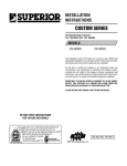
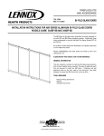
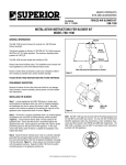
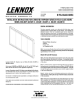
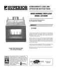
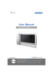
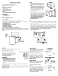
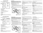
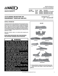
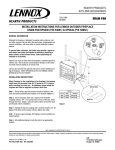
FIREPLACE KITS
AND ACCESSORIES
904665
REV. C 03/2008
GLASS DOOR/END PANEL
INSTALLATION INSTRUCTIONS FOR ABF GLASS DOOR/END PANEL PACKAGED SET
MODELS 38ACR AND 38ACR-BB
A
J
K
H
G
C
B
Lennox's Glass Door/End Panel Packaged Set, Models 38ACR and
38ACR-BB, are designed to be installed on the CR-3835R/L Series
fireplaces. These kits come complete with all of the required hardware
necessary to complete the task.
F
E
Please read and understand these instructions carefully before beginning installation and operation. Do not attempt to alter or modify the
construction of these glass door assemblies as it could cause a malfunction or possible fire hazard.
The Models 38ACR and 38ACR-BB have been tested and listed by Omni
Test Laboratories, Inc.
D
Figure 1
END PANEL INSTALLATION STEPS
PLEASE RETAIN THIS MANUAL FOR FUTURE REFERENCE.
Step 1. Remove the screen rod covers from the front and corner
openings. Remove two angle retainers and replace screws.
GENERAL INFORMATION
Before starting the installation of the glass doors and end panel, assure
the kit is complete and undamaged. Refer to Figure 1 and the inventory
list to identify all necessary parts.
INVENTORY LIST
A. (1) Top Channel (door)
B. (1) Bottom Channel (door)
C. (1) Top Channel (panel)
D. (1) Bottom Channel (panel)
E.(1) Corner Post
F. (1) Glass End Panel
G. Door Panel Assembly LH
H. Door Panel Assembly RH
J. (2) Baffles
K. Hardware Kit (Including
Handles) Installation Instructions
Note: Units are shipped without covers installed.
Step 2. Refer to Figure 2 and remove the top two outer screws and loosen
the bottom screws at least two (2) turns. Remove corner shipping post,
if installed.
CAUTION: REMOVE THE PLASTIC PROTECTIVE COATING FROM ALL
BRASS PIECES BEFORE INSTALLATION.
US
NOTE: DIAGRAMS & ILLUSTRATIONS NOT TO SCALE
1
TOOLS REQUIRED
• Phillips screwdriver (small or medium)
Do Not
Touch
Loosen (At Least
Two (2) Turns)
Loosen (At Least
Two (2) Turns)
Remove
And Retain
Note: The pins on the glass end panel require
repositioning when the door is fitted into an
opposing right or left hand opening. To shift
the pins, loosen the pins using a 3/8" open end
wrench and slide the pins as required along the
frame channel. Position the door squarely
within the opening equally gapped at the right
and left sides and secure the pins in place by
tightening with the wrench.
Outside
End Panel
Top Channel
Remove
And Retain
Loosen All Lower Screws
(At Least Two (2) Turns)
Figure 6
Remove
Shipping
Corner Post
Screw
(2 Places)
Corner
Post
Figure 2
Step 3. Slide the end panel bottom channel into
position and tighten the end screws that were
previously loosened. Install the top track over
the middle screw and secure with the screws
removed and retained in Step 2.
End Panel
Bottom Channel
Step 3. Refer to Figures 2 and 7 and slide the
door bottom channel into position. Secure by
tightening screws previously loosened through
the holes provided on the top face of the channel. Install the door top channel over the middle
screw and secure it in place with four screws,
two screws previously removed and two screws
previously loosened.
Figure 4
BI-FOLD DOOR
INSTALLATION STEPS
Step 1. Attach the polished metal and wooden
handle assemblies to the lower door frames
(Figure 5 ). Use the No. 8-32 x 1/4 Philips pan
head screws and associated nuts provided in
the hardware kit. There is a single screw and
nut for use with each handle assembly. Slide
the nuts into the frame channel and insert the
screws through the handle brackets and then
into the nuts. Position the handle assemblies
approximately as shown on the front page of
this document and tighten the screws to secure
the handles in place.
Figure 3
Figure 7
Step 4. Starting with either the right or left door
assembly. Engage the hinge pin into the hole in
the clip within the top door channel. The roller
pin must be positioned within the upper door
guide track (Figures 8 and 9 ).
Step 4. Refer to Figures 3 and 4 and install the
corner post to the ends of the end panel top and
bottom channels. Secure it in place with two
screws from the hardware kit.
Step 5. Insert the upper pins of the end panel
assembly into the holes in the top channel.
Swing the bottom portion of the end panel over
the bottom channel and insert the lower pins
into the bottom channel.
Pivot Pin
Figure 5
CAUTION: DO NOT OVER-TIGHTEN HANDLE
SCREWS.
Step 2. Install two (2) baffles, one above the
other with the black No. 8-15 x 1/2" Phillips pan
head screws from the hardware kit (Figure 6 ).
2
NOTE: DIAGRAMS & ILLUSTRATIONS NOT TO SCALE
Figure 8
Roller Pin
Hinge Pin
Upper Door
Guide Track
Roller Pin
*Note: Upper door hinge pins can also be
loosened for adjustment purposes; however, it
is easier to loosen lower pins.
GENERAL OPERATING PRECAUTIONS
AND INSTRUCTIONS
Figure 9
Step 5. Lift and swing the lower corner of the
door over the hole in the bottom door channel
and engage the shorter hinge pin into this hole
(Figures 10 and 11 ).
CAUTION: THESE GLASS DOORS ARE
LISTED ONLY FOR USE WITH THE SUPERIOR FIREPLACE OR APPLIANCE MODELS
SHOWN. USE ON ANY OTHER FIREPLACE
OR APPLIANCE MAY CONSTITUTE A POTENTIAL FIRE HAZARD.
• Avoid building extremely large fires as the
tempered glass could become damaged.
CLEANING
NEVER CLEAN THE GLASS WHEN THE DOORS
ARE HOT. DO NOT USE AMMONIA OR ANY
AMMONIA BASED GLASS OR HOUSEHOLD
CLEANER TO CLEAN THE GLASS OR THE DOOR
FRAME. AN AMMONIA BASED CLEANER WILL
DAMAGE THE FINISH.
Remove dirt and grime from the doors using a
clean dampened towel followed by wiping with
a dry towel. To remove stubborn stains from
the doors, use a mild soap solution and towel to
gently scrub away stain. Take care not to scratch
the glass surface. Do not use abrasive cleaners.
IMPORTANT
• Use fireplace tools carefully to avoid striking
the glass.
Bottom
Door
Channel
• Keep wire mesh screens closed during fireplace use.
• The fireplace flue damper must remain open
until fire is completely out.
Pivot
Point
• Assure wood and embers are well within the
confines of the grate area and well away from
the glass doors.
Figure 10
• Keep glass doors closed at night when retiring to minimize the loss of heated room air up
the vent.
CAUTION: THE CORNER FIREPLACE OR APPLIANCE SHOULD ONLY BE OPERATED WITH
THE BI-FOLD GLASS DOORS FULLY OPEN OR
FULLY CLOSED (FIGURE 12 ).
End Panel
Tempered glass will break into small particles if
it should shatter unexpectedly. If the glass
breaks, particles of extremely hot glass could
be discharged into the surrounding environment, thereby creating a risk of personal injury
or fire. Observation of the above operating
precautions and instructions will reduce the
risk of personal injury or fire.
Extreme temperature changes can cause breakage — do not build a hot fire and close the
doors if the doors are cold.
If the tempered glass pane becomes scratched
or chipped, it creates a weakness in the glass
which can cause the glass to break when heated.
Replace the pane of glass by contacting your
nearest LHP Distributor. For the name of your
nearest distributor contact:
LENNOX HEARTH PRODUCTS
1110 West Taft Avenue
Orange, CA 92865
Lower Hinge Pin
Figure 11
Step 6. Repeat this procedure for the opposite
door assembly.
ADJUSTMENT FOR DOOR ALIGNMENT
The doors are properly adjusted when the top
door trim is in a straight, level line and the gap
between the doors is even at the top and
bottom. If adjustments are required, grasp the
door handle and loosen the lower door hinge
pin using a 3/8" open end wrench*. Slide the
door panel on the hinge pin until the gap
between the upper door trim and upper frame
is even. Retighten the lower door hinge pin*.
Repeat this procedure for the opposite door if
needed.
These glass doors utilize tempered glass
which is designed for use with high temperatures but can unexpectedly shatter. DO NOT
SIT CLOSE TO THE GLASS.
Fully Open or
Fully Closed
Figure 12
CAUTION: GLASS AND METAL FRAMES GET
HOT — ALWAYS USE HANDLES TO OPEN AND
CLOSE THE DOORS.
NOTE: DIAGRAMS & ILLUSTRATIONS NOT TO SCALE
WARNING: DO NOT BURN TRASH,
CONSTRUCTION SCRAPS, RAILROAD
TIES, OR OTHER HIGHLY-FLAMMABLE MATERIAL IN THE FIREPLACE. INTENSE HEAT CAN CAUSE
THE GLASS TO LOSE STRENGTH AND
RESILIENCE WHICH WILL RESULT IN
GLASS BREAKAGE.
3
The manufacturer reserves the right to make changes at any time, without notice, in design, materials, specifications, prices and also to discontinue colors, styles and products.
Consult your local distributor for fireplace code information.
Printed in U.S.A. © 1999 by LENNOX HEARTH PRODUCTS
4
P/N 904665 REV. C 03/2008
NOTE: DIAGRAMS & ILLUSTRATIONS NOT TO SCALE
1110 West Taft Avenue • Orange, CA 92865