1
INSTRUCTION MANUAL
MclNTOSH MODEL MC-60
60 WATT POWER AMPLIFIER
Type A-121
Serial No. 5F846 and above
MclNTOSH LABORATORY, INC.
2 Chambers St.
Binghamton, N. Y.
U.S.A.
ELECTRICAL AND MECHANICAL SPECIFICATIONS
Specifications for the Mclntosh Model MC-60 Audio Amplifier
Power Supply
117/125 volts, 50/60 cycles
Power Consumption
280 watts at 60 watts output
155 watts at zero signal output
Power Output
60 watts continuous
Input Level
Input #1, 0. 5 volts to 30 volts, with gain control
Input #2, 2. 5 volts (for use with Mclntosh Audio
Compensators and Pre-Amps)
Frequency Range
20 to 30, 000 cycles ± .1 db at 60 watts output
16 to 60, 000 cycles ± .5 db at 60 watts output
1.0 to 100, 000 cycles ± 1.0 db at 30 watts output
Harmonic Distortion
Less than 0 . 5 % at 60 watts output or less, 20
to 20, 000 cycles.
Intermodulation Distortion
Less than 0 . 5 % instantaneous peak power is below 120 watts
Impulse Distortion
Negligible
Noise and Hum Level
90 db or more below rated output
Damping Factor
12 or better for 4, 8, and 16 ohm output, 16
for 600 ohms
Input Impedance
0. 5 meg for 0. 5 volt input and 0. 13 meg for
2. 5 volt input, 20 cycles to 40 KC
Output Impedance
4, 8, 16, 83 (70.7 volts) and 600 ohms (600 ohm
is balanced to ground)
Phase Shift
±8° 20-20.000 cycles
Tube Complement
Rectifier:
Pre-Amp:
Phase Inverter:
Voltage Amp:
Driver:
Output:
Auxiliary Equipment Connection
Designed to power C-4, C-8 and other Mclntosh
pre-amplifiers
Size
14" x 10" x 8" high, chassis type construction
Weight
46 pounds net
Finish
Chrome and Black
2-5U4GB
12AX7
12AU7
12BH7
12AX7
2 KT-88/6550
DESCRIPTION
The Mclntosh Model MC-60 is a 60 watt high fidelity power amplifier designed f o r home
entertainment systems and professional applications where high power and distortion free
performance is required. The Model MC-60, like all other Mclntosh power amplifiers, uses
the exclusive Mclntosh high efficiecny output circuit and bifilar output transformer to obtain
the high standard of performance found in this amplifier. Some of the more important characteristics of the amplifier are; less than 0. 5% harmonic distortion at any power output up to
60 watts and at any frequency in the audio spectrum, 20 to 20, 000 cps; less than 0. 5% intermodulation distortion f o r all power levels up to 120 instantaneous peak watts; and noise and
hum level 90 db or more below the rated output level.
The MC-60 has two high impedance inputs and may be operated from any signal source
delivering 0. 5 volts or more, or directly from a Mclntosh Audio Compensator or Pre-Amplifier.
Output impedance of 4, 8 and 16 ohms are provided for direct connection to loudspeakers.
Additional outputs for 83 ohms ( 7 0 . 7 volts) and 600 ohms are provided f o r use
with multiple speaker systems, lines, etc.
INSTALLATION
Location
The MC-60 should be located in a well-ventilated area. If the amplifier is housed in a
cabinet or other enclosure, holes must be provided f o r air circulation.
Input Connections
1. When a Mclntosh Audio Compensator or Pre-Amplifier of the non-self powered type
is used with the MC-60, plug the pre-amplifier's output-power cord into the "PRE-AMP
INPUT" receptacle on the MC-60 and turn the "GAIN" control fully counter clockwise. This
receptacle supplies the required plate and filament power to the pre-amplifier equipment as
well as providing the necessary audio connections.
For pre-amplifier installation,
instruction manual.
adjustment and operation refer to the pre-amplifier's
2. When using a self-powered Mclntosh Audio Compensator or Pre-Amplifier, connect
the audio output from the pre-amplifier to the input of the MC-60 using the cable supplied
with the pre-amplifier. Turn the "GAIN" control fully counter clockwise.
3. When a signal source of 0. 5 volts or more is used to drive the MC-60, such as the
output of a tuner, tape recorder, or other pre-amplifiers, plug the source into the"0. 5 VOLT"
pin jack receptacle or connect to the "0, 5 VOLT" and "GND" screw terminals.
Use the
"GAIN" control to obtain the desired operating level.
If desired, the signal source may be wired to an octal plug for insertion in the octal
"Pre-Amp Input" receptacle.
In this case connect the input lead to pin #5 and the ground
lead to pin #1. When using this connection the source must not have a DC output component.
Output Connections
The MC-60 has output impedances of 4, 8 and 16 ohms available at either the screw
terminal connector or the output socket. In addition, a 600 ohm output (balanced to ground)
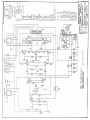
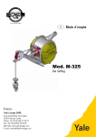
is available at the output socket. See schematic diagram for socket connections.
It is important that the loudspeaker or other load be properly matched to the amplifier
if best performance is to be obtained. Because many loudspeakers do not have voice coil impedances exactly matching 4, 8 and 16 ohms, the following table lists suggested connections
for the best impedance matching.
Speaker Impedance
Connect to
3. 2 to 6. 5 ohms
4 ohms
6. 5 to 13 ohms
8 ohms
13 to 32 ohms
16 ohms
WARNING: Output plugs wired for Mclntosh 20W-2 and 50W-2 amplifiers must not be
used with the MC-60 without rewiring the plug.
Output connections for the MC-30 are the same as those for the MC-60.
Power Connections
The MC-60 operates from any 110 to 130 volt 50-60 cycles power line. (When continuous use is contemplated on 120 to 130 line volts the transformer primary should bo re-connected using the 125 volt tap.)
When the MC-60 is used with Mclntosh Pre-Amplifier equipment, tuners, or other
associated equipment, the MC-60 power cord may be plugged into the receptacle at the rear
of these units. When thus connected the power switch of these units controls the MC-60.
GUARANTEE
We guarantee the performance of this equipment arid the mechanical and electrical
workmanship to be free of defects for a period of 90 days. This guarantee does not extend
to components damaged by improper use nor does it extend to transportation to and from the
factory.
SERVICE INFORMATION
All Mclntosh equipment is designed for long trouble free operation. All components
are of the highest quality and are conservatively operated. If trouble develops the amplifier
may be serviced by your franchised dealer, a competent serviceman, or returned to the
factory. Equipment will not be accepted at the factory unless factory return authorization
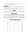
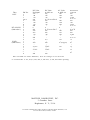
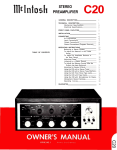
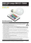
is first received. The following chart of operating voltages and resistances is offered as a
guide for servicing the unit. All voltages and resistances are measured to chassis except
those with asterick {*). These are measured to chassis with pin #2 of either 5U4GB grounded. Voltages are measured with high impedance VTVM NOTE - UNIT MUST BE TURNED
OFF WHEN MEASURING RESISTANCES.
Tube
12AX7
(Input)
12AU7
Pin No.
1
2
3
4& 5
6, 7, 8
9
1
134
0
1.2
Fil
-
Fil
1.5
.4
1. 1
.4
11
330K*
1M
3.3K
0 to 70
0 to 70
40*
1.5
330K*
6. 3 V. ac to pin 9
235
120
3&a
4& 5
Fil
6
270
110
126
0.6
6 . 3 V ac to Pin 9 235
11
100
0_
_
Fil
340
0
16
Fil
340
0
Fil
290
148
0
11
14
0.32
6. 3V ac to Pin 9
290
148
0
11
-
7
9
1
2
3 & 8
4& 5
6
7
9
Resistance
Unit Off
120
0
270
134
138
2
12BH7
VOLTAGE AND RESISTANCE CHART
DC Volts
DC Volts
AC Volts
No Signal
at 60W out
at 60W out
18K
0 to 70
43K*
2.6M*
0 to 70
12K*
20 OK
1.2K
0 to 70
12K*
200K
0 to 70
Tube
12AX7
Pin No.
1
2
3
4&5
6
7
a
9
KT-88/6550
(Both tube*)
1
2
3
4
5
6
7
5U4GB
(Both tubes)
8
1
2
3
4
5
6
7
8
DC Volts
No Signal
DC Volts
at 60W out
435
-46
365
-45
Fil
435
-46
-45
Fil
0
Fil
435
435
-45
-
Fil
.8
440
37 5 AC
AC Volts
at 60W out
-46
-45
6.3V ac to Pin 9
36S
106
148
148
-
106
.46
-45
-
148
148
-
0
0
6. 3V.ac to Pin 7
106
110
365
365
-45
2.5
-
380
-
148
110
8.9(ripple)
Resistance
Unit Off
45*
1M
270K
0 to 70
45*
1M
27 OK
0 to 70
-
0 to 70
45*
45*
270K
0 to 70
12
0*
-
37 5 AC
-
370AC
-
15
15
-
440
380
0*
-
370AC
370
370
Pins not listed are either filaments, have no voltage or are not used.
U. S. Patents No. 2. 477, 074; 2, 545, 788; 2, 646. 467; 2, 654, 058 others pending.
MclNTOSH LABORATORY, INC.
2 Chambers Street
Binghamton, N. Y., U.S.A.
In Canada: Manufactured Under License by McCurdy Radio Industries, Ltd.
22 Front Street West, Toronto, Canada
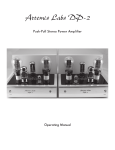
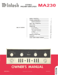
SERIAL NO 3FB46 AND ABOVE
Plate
Plate
Choke
Choke
C1 .1mF, 200V
C2 100mF, 12V
C3 8mF, 250V
C4
.22mF, 400V
C5 ,047mF, 600V
C6 .047mF, 600V
C7 .22mF, 600V
C8 .22mF, 600V
C9
.47mF, 200V
C10 .47mF, 200V
C11 470mF,
500V
C12A 35mF, 500V
C12B 80mF, 500V
C12C 15mF, 450V
C13A 35mF, 500V
C13B 80mF, 500V
C13C 15mF, 450V
C14 8mF, 250V
CH1
CH2
PRE-AMPLIFIER INPUT
SOCKET CONNECTIONS
Pin 1
- Ground
Pin 2
- Pre-Amp Input (2.5V)
Pin 3
- Not used
Pin 4
- +360V at 3.5 mA
Pin 5
- Pre-Amp input (0.5V)
Pin 6
- not used
Pins 7 & 8 - 6.3V at 1 Amp
R1 250K POT (GAIN A D J . )
R2 100K
R3 27K
R4 1M
R5 3.3K
R6 68 5%
R7 100K
R8 330K
R9 680K
R10 18K 1W
R11 2.2M
R12 27K 5%
R13 30K 5%
R14 220K
R15 220K
R16 330K
R17 12K* 2W
R18 12K* 2W
R19 1.2K
R20 56K 5%
R21 1M
R22 1M
R23 100K 5%
R24 56K
R25 56K
R26 56K
R27 56K
R28 220 1W
R29 220 1W
R30 1.3K 5%
R31 10K 10W
R32 10K 2W
R33 250 OHM POT (HUM ADJ.)
*Matched to within 1%
OUTPUT CONNECTIONS
USING OCTAL SOCKET
4
ohms
- pins 1 & 2
8
ohms
- pins 1 & 3
16 ohms - pins 1 & 4
500/600 ohms - pins 7 & 8
(pin 6 is CT and ground)
70.7 volts - pins 5 & 6
(pin 6 is ground)
038-177
Be102002