1
INSTRUCTION MANUAL
McINTOSH MODEL MC-30
30 WATT POWER AMPLIFIER
Type A-116B
Serial #9E341 and above
038-243
MCINTOSH LABORATORY, INC
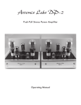
DESCRIPTION
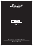
The McIntosh Model MC-30 is a 30 watt high fidelity power amplifier designed for home entertainment s y s t e m s and p r o f e s s i o n a l applications. The Model MC-30 is similar to the earlier
McIntosh Model A-116 30 watt amplifiers and includes all of the rigid electrical specifications
and features found in these earlier units plus: less than 1 / 3 % harmonic distortion at any power
output up to 30 watts and at any frequency in the audio spectrum, 20 to 20,000 cps; less than
1/2% intermodulation distortion if instantaneous peak power is below 60 watts for any combination of frequencies 20 to 20, 000 cps; and noise and hum level 90 db or more below rated o u t p u t .
The famous McIntosh high efficiency output circuit is used to obtain the high standard of performance found in this amplifier.
The MC-30 maybe operated from any signal source d e l i v e r i n g 0. 5 or more volts, or d i r e c t l y
from a McIntosh Audio Compensator or Pre-Amplifier, such as the Models C-8, C-4, C-104,
or C-108. Output impedances of 4, 8 and 16 ohms are provided for direct connection to loudspeakers. Additional outputs for 166 ohms (70.7 volts) and 600 ohms are provided for use with
multiple speaker systems, lines, etc.
INSTALLATION
Location
The MC-30 should be located in a ventilated area. If the amplifier is housed in a cabinet or
other enclosure, holes should be provided for air c i r c u l a t i o n .
Input Connections
1. When a McIntosh Audio Compensator or other McIntosh p r e - a m p l i f i e r is used with the
MC-30, plug the pre-amplifier's output-power cord into the " P r e - A m p input" receptacle on the
MC-30 and turn the "gain" control fully counter clockwise. This receptacle supplies the required plate and filament power to the p r e - a m p l i f i e r e q u i p m e n t as well as providing the necessary audio connection.
For pre-amplifier installation and operation refer to the p r e - a m p l i f i e r ' s i n s t r u c t i o n manual.
2, When a signal source of 0. 5 volts or more is used to drive the amplifier, such as the
output from a tuner, tape recorder, or pre-amplifier, plug the source into the "0. 5 volt input"
pin jack receptacle or connect to the "0.5 volt" and "GND" screw terminals. Use the "gain"
control to obtain the desired operating level.
GUARANTEE
We guarantee the performance of this equipment and the mechanical and electrical workmanshipto be free of defects for a period of 90 days. This guarantee does not extend to components
iamaged by improper use nor does it extend to transportation to and f r o m the f a c t o r y .
SERVICE I N F O R M A T I O N
All McIntosh equipment is designed far long trouble f r e e o p e r a t i o n . All c o m p o n e n t s are of
highest quality and are conservatively operated. If t r o u b l e develops the a m p l i f i e r m a y be s e r viced by your franchised dealer, a competent s e r v i c e m a n , or r e t u r n e d to the f a c t o r y . E q u i p ment will not be accepted at the f a c t o r y unless f a c t o r y r e t u r n a u t h o r i z a t i o n is f i r s t r e c e i v e d .
The following chart of operating v o l t a g e s and r e s i s t a n c e s is o f f e r e d as a g u i d e for s e r v i c i n g the
unit. All voltages and r e s i s t e n c e s a r e m e a s u r e d to c h a s s i s e x c e p t those w i t h a s t e r i s k (*).
These are m e a s u r e d to chassis with pin #2 of the 5U4GB g r o u n d e d . V o l t a g e s are m e a s u r e d
with high impedence V T V M . N O T E - - U N I T MUST BE T U R N E D OFF WHEN MEASURING RESISTENCES.
VOLTAGE A N D RESISTANCE CHART
Tube
12AX7
(Input)
Pin No.
DC Volts
No Signal
DC Volts
at 30W out
1
2
3
4&5
6, 7, 8
9
134
0
1.2
Fil
Fil
120
0
1. 1
6. 3 V. ac to Pin 9
-
1. 3
0. 24
0. 22
-
330K*
1M
3.3K
0 to 70
0 to 70
12AU7
1
2
3&8
4&5
6
7
9
270
134
138
Fil
270
110
Fil
235
120
126
6. 3 V. ac to Pin 9
235
100
•
9
13
0. 57
9
0
-
40*
330K*
13K
0 to 70
43K*
26M*
0 to 70
12BH7
1
2
3&8
4&5
6
7
9
355
0
16
Fil
355
0
Fil
295
0
14
6. 3 V. ac to Pin 9
295
0
-
132
9
0. 32
12K*
220K
1.2K
0 to 70
12K*
220K
0 to 70
AC Volts
at 30W out
132
9
-
Resistance
U n i t off
ELECTRICAL AND MECHANICAL SPECIFICATIONS
Specifications for the McIntosh Model MC-30 Audio Amplifier
Power Supply
117/125 volta, 50/60 cycles
Power C o n s u m p t i o n
135 watts at 30 watts output
105 watts at zero signal output
Power Output
30 watts continuous
Input level
Input #1 (pin jack and screw terminals and pin
5 of pre-ampsocket) .5 volts to 30 volts, with
gain control Input #2 (pin 2 of pre-amp socket)
2. 5 volts, (For use with McIntosh pre-amplifier equipment)
Frequency Range
20 to 30, 000 cycles ± .1 db at 30 watts output
15 to 50,000 cycles ± .5 db at 30 watts output
10 to 100.000 cycles ± 1 db at 15 watts output
Harmonic
Less than 1/3% at 30 watts output or less, 20
to 20, 000 cycles
Distortion
Intermodulation Distortion
Less than 1/2% if instantaneous peak power
is below 60 watts for any combination of frequencies 20 to 20, 000 cycles
Impulse Distortion
Negligible
N o i s e and Hum Level
90 db or more below rated output
Damping Factor
12 or better for 4, 8 and 16 ohm output, 16
for 600 ohms
Input Impedance
0. 5 meg for 0. 5 volt input and 0. 13 meg for
2. 5 volt input. 20 cycles to 40 Kc
Output Impedance
4, 8, 16. 166 (70. 7 volts) and 600 ohms (600
ohm is balanced to ground)
Phase Shift
20 cycles 3°
20, 000 cycles 9°
Tube Complement
Pre-Amp: 12AX7
Phase Inverter: 12AU7
Voltage Amp: 12 BH7
Driver: 12AX7
Output: 2--6L6 GC/1614
Rectifier: 5U4-GA
Auxiliary Equipment
connection ("Pre-Amp
input" receptacle)
Designed to power C-8 and other McIntosh
Pre-Amplifiers
Size
13" x 8" x 8" high, chassis type construction
Weight
30. 5 pound, net
Finish
Chrome and Black