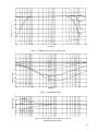
1
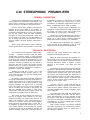
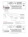
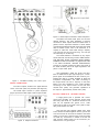
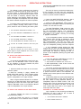
STEREO
PREAMPLIFIER
C20
GENERAL DESCRIPTION
TECHNICAL DESCRIPTION
Mechanical Specifications
Electrical Specifications
FRONT PANEL FACILITIES
INSTALLATION
CONNECTING
A-C Connections
Input Connections
Output Connections
Ground Connections (Program Sources)
TABLE OF CONTENTS
OPERATING INSTRUCTIONS
Balancing a Stereo System
To Adjust for Balance in the Treble
Range
To Adjust for Amplitude Balance in
the Bass Range
Adjusting Phase
Listening to a Stereo Record
To Adjust the Balance Control After the
System has been Balanced
Adjusting for Special Effects
Using the C20 with a Stereo Tuner
Using the C20 with a Stereo Tape Machine_
Using the C20 Front Panel Tape Jacks
Using the C20 w i t h Tape Decks
Using the C20 with Microphones for Stereo.
Monophonic Record Settings
Operating Curves
GUARANTEE
1
1
2
2
2
5
6
6
7
9
9
10
10
10
10
10
10
11
11
11
11
12
12
12
12
14
16
C20
C20 STEREOPHONIC PREAMPLIFIER
GENERAL DESCRIPTION
The Mclntosh C20 Stereophonic Pre-amplifier is a
control center for any stereophonic sound system. This
control center is necessary to accurately perform four
specific functions to increase the enjoyment of stereo.
is affected by variations in environment. Also, people
listening to the music have varying ideas of correct
tone balance. To adequately compensate for these conditions, a high-quality control center is needed.
First, the control center amplifies weak electrical
impulses. As the record rotates on the turntable, undulations in the grooves move the pick-up stylus approximately one-thousandth of an inch, in any direction,
from the rest position. From this slight mechanical
movement, the pick-up stylus generates a weak electrical impulse on the order of a few thousandths of a
volt. To amplify and preserve the character of such an
electrical impulse, the finest amplifier performance is
required.
Third, there is a great variety of stereophonic and
monophonic records manufactured today, both domestic
and foreign. The control center must provide record
compensation for a great variety of recordings.
Second, every sound system is used in a different
acoustical environment. The tone balance of the music
Fourth, with programs originating from a variety of
sources such as tuners, records, tape machines, microphones, etc., a control center is needed to select and
switch these sources separately or in combination.
All of these jobs are performed with excellence
by the C20 and yet this instrument is easy to mount,
simple to operate, and is the finest in appearance.
TECHNICAL DESCRIPTION
You now own the finest expression of stereo craftsmanship . . . designed and built to fulfill your needs.
Through direct consumer contact, a unique Mclntosh
marketing research program determines the application
of electronic and mechanical engineering to fit your
needs. Relentless research by Mclntosh engineers improves the selection of materials and the circuits in
which they are used. It is this total concept of craftsmanship directed to consumer satisfaction that has
maintained the Mclntosh reputation for excellence in
performance, quality, and reliability.
Perhaps you would like to know a few of the
features developed through research based on consumer needs that place your C20 Pre-amplifier above
all other pre-amplifiers.
An example of the unique mechanical construction
throughout is emphasized on the back panel where lowvoltage program sources are connected to the C20. This
portion of the panel is cut out and mounted on small
electrical insulators. The ground circuit is connected
to the main chassis at only one point. By breaking the
path for circulating hum currents in this manner, the
hum and unwanted noises induced in other stereo
systems when used with various program sources and
combinations of program sources are eliminated.
Hum noises are also introduced into stereo systems by the magnetic fields produced by the power
transformer windings. The greatest care went into the
design and construction of the power transformer in
your C20. It is wound in such a way that the magnetic
fields produced by the windings tend to cancel. This is
accomplished by splitting the windings into two segments. Further reduction of the magnetic field intensity
is achieved through the use of additional magnetic and
electrical shielding. With these construction improve-
ments the hum noises introduced by ordinary preamplifiers are eliminated by the C20.
Nearly all of the small resistor and capacitor component parts in the C20 are mounted on military-type
terminal boards. This specialized construction prevents
damaging mechanical strains. In addition it makes
servicing, if ever required, much easier and more
effective.
The mechanical layout of the C20 allows maximum
separation of the left and right channels. The terminal
board at the rear of the C20 is associated with the right
channel and the terminal board at the front with the
left channel. C20 terminal boards are constructed of
natural bakelite because of its low-volume resistivity.
This prevents the gradual increase of electrical noise
common to other terminal board materials after continued use of the control center.
The C20 is the only control center that has an
illuminated front panel to provide convenient reading
under low-level lighting conditions. This feature is of
particular importance when a closet is adapted to house
stereo equipment.
Front panel tape input jacks are another exclusive feature provided by the C20. With the start of
stereo FM broadcasting it will be important to tape
and preserve those special programs that will otherwise never be heard again. This feature will be greatly
appreciated by you and your friends when recording
on portable tape machines.
Only extensive research and planning combined
with skilled engineering and manufacturing knowhow,
directed toward consumer needs, can produce such a
fine electronic instrument.
1
MECHANICAL SPECIFICATIONS
DIMENSIONS
Chassis: 14-1/2 inches wide; 4-1/2 inches high; 12
inches deep
WEIGHT
Chassis: 18 pounds
Shipping Weight: 28.5 pounds
Front Panel: 15-5/8 inches wide; 4-7/8 inches high
Front Panel Mounting Space Required: 16-3/8 inches
wide; 5 inches high
FINISH
Anodized gold and black (front panel)
ELECTRICAL SPECIFICATIONS
POWER REQUIREMENTS
117 volts, 50/60 cycles, ac, 35 watts
Low-level inputs: less than 2 microvolts at input terminals
INPUT SENSITIVITY AND INPUT IMPEDANCE
Auxiliary: 0.25 volt; 470,000 ohms
Tape: 0.25 volt; 470,000 ohms
Tuner 1: 0.25 volt; 470,000 ohms
Tuner 2: 0.25 volt; 470,000 ohms
Phono 1: 2 to 10 millivolts; 47,000 ohms for low-output
cartridge
10 to 70 millivolts; 47,000 ohms for high-output
cartridge
0.1 volt; 220 mmf in series with 47,000 ohms for
Xtal or ceramic cartridge
Phono 2: Same as phono 1
Tape Head 1: 2 to 10 millivolts; 47,000 ohms for lowoutput head
10 to 70 millivolts; 267,000 ohms for high-output
head
Tape Head 2: Same as tape head 1
Tape Compare (Monitor): 0.25 volt; 115,000 ohms
FREQUENCY RESPONSE
±0.5db ; 20 to 20,000 cycles
MAIN OUTPUT
2.5 volts with rated input
2 output jacks in parallel for each channel
DISTORTION
Less than 0.2% at rated output, 20 to 20,000 cycles
HUM AND NOISE
High-level inputs: 85 db below rated output
TAPE OUTPUT
0.25 volt with rated input
1 output jack for each channel
LEFT PLUS RIGHT OUTPUT
2.5 volts from generator impedance of 23,000 ohms
VOLTAGE AMPLIFICATION
Low-level inputs to Main Output: 1,000 to 1 (60 db) at
1000 cycles
Low-level inputs to Tape Output: 100 to 1 (40 db) at
1000 cycles
High-level inputs to Main Output: 10 to 1 (20 db)
High-level inputs to Tape Output: 1 to 1 (0 db)
Tape Compare (Monitor) input to
Main Output:
10 to 1 (20 db)
A-C AUXILIARY OUTLETS
1 unswitched for tape machine or turntable,
colored Red
4 switched, colored Black
FRONT PANEL FACILITIES
Figure 1. C20 Front Panel
2
INPUT SELECTOR
L . . . left channel to left speaker, no program to
right speaker.
INPUT SELECTOR
PHONO 1
TUNER
2
S
M
R . . . right channel to right speaker, no program
to left speaker.
S
PHONO 2
1
M LEFT . . . left channel only to both speakers.
M
M RIGHT . .. right channel only to both speakers.
TAPE
1
TAPE HD
AUX
2
RECORD COMPENSATOR
This ten-position program switch connects the
C20 as follows:
AUX ... any auxiliary service, such as a television
set, an extra tuner, or any other program source
requiring flat amplification.
RECORD COMPENSATOR
BASS
TREBLE
400
RIAA
-10
-12
UP
300
-5
TAPE
0
RIAA
LP
TAPE
TAPE . . . any self-contained tape machine (tape
machine having its own playback preamplifier).
TUNER 1 & 2 . . . AM and FM outputs from a
stereo tuner or a pair of stereo tuners.
PHONO 1 & 2 — S & M . . . stereo or monophonic
operation with the following types of phono cartridges.
These controls are used to correct for program
equalization introduced by the recording process.
Table 3 gives the recommended settings of the RECORD
COMPENSATOR controls of the C20 for monophonic
recordings.
a. Constant amplitude cartridges such as crystal,
ceramic, or frequency-modulated devices.
BASS AND TREBLE
b. Magnetic cartridges having an output of 10mv
or more. Maximum input voltage for this output
is 70mv.
TREBLE
BASS
-
c. Magnetic cartridges having an output of less
than 10mv.
°
+
-
°
+
TAPE HEAD—1 & 2 ... a tape deck or a pair of
tape decks that do not contain their own playback
preamplifiers. Two types of tape head outputs can
be used in this position.
a. Tape heads having an output of less than 10mv.
b. Tape heads having an output of 10mv or more.
Maximum input voltage for this output is 70mv.
BASS . . . clockwise rotation increases bass loudness; counterclockwise rotation decreases bass
loud ness.
MODE SELECTOR
MODE SELECTOR
L
STEREO
REV
There are two tone controls on the C20—BASS
and TREBLE.
R
M LEFT
TREBLE . . . clockwise rotation increases treble
loudness; counterclockwise rotation decreases
treble loudness.
M RIGHT
PHASE
This six-position switch connects the C20 for
proper left-right distribution of sound for the program
source selected. Its positions are as follows:
PHASE
180°
0°
REV . . . connects left channel to right speaker,
right channel to left speaker, corrects for leftright reversal of program.
STEREO . . . this is the normal stereo MODE
SELECTOR position; left channel to left speaker,
right channel to right speaker.
This two-position switch reverses the phase in the
left channel to correct for speaker or program phasing.
3
BALANCE
With the RUMBLE FILTER button pushed to the
IN position, low-frequency rumble noise below 60 cps
created by a turntable or changer and undesirable
acoustically coupled feedback are reduced.
BALANCE
0
LEFT
RIGHT
TAPE JACK
TAPE
JACK
This control balances the C20 for unequal program sources.
LEFT . . . turning the control to the left slowly
reduces the right channel to no output and
accents the left channel.
RIGHT . . . turning the control to the right slowly
reduces the left channel to no output and accents
the right channel.
HF CUTOFF FILTER
IN-PLAYBACK
OUT-RECORD
This pushbutton controls the signal direction to
or from the front panel telephone jacks.
IN-PLAYBACK . . . TAPE input is switched from
rear tape jacks to front panel telephone jacks.
HF CUTOFF FILTER
9KC
FLAT
5KC
Any program originating from a portable machine
connected to the C20 can be heard by rotating
the INPUT selector to the TAPE position.
OUT-RECORD . . . connect signals from the rear
tape jacks to the INPUT SELECTOR TAPE position. Any program picked up by the C20 is connected to the portable machine for recording,
This three-position switch minimizes surface noise
when reproducing old, badly worn recordings. Its positions are as follows:
TAPE COMPARE
FLAT... filter disconnected.
9KC .. . rolls off response sharply starting at 9KC.
5KC . . . rolls off response sharply starting at 5KC.
TAPE
COMPARE
LOUDNESS
IN-TAPE
L0UDNESS
2
3
I
4
FLAT
5
Music reproduced at very low volume loses its
bass and treble due to a selective shift in sensitivity
of human hearing. This effect is known as the FletcherMunson hearing characteristics. (See page 15, Figure
13.) The LOUDNESS control corrects for this effect.
This pushbutton makes it possible to instantaneously compare the recorded material with the source
signal. TAPE COMPARE jacks are provided on the back
panel to accept a signal- from a tape recorder with a
monitor head and preamplifier. When the TAPE COMPARE pushbutton is in the out position, the program
source is fed through the power amplifiers and the
loudspeakers. When the TAPE COMPARE pushbutton
is in the IN position (depressed), the signal source
becomes the monitored program from the recorded tape
and is fed through the power amplifiers and loudspeakers.
RUMBLE FILTER
IMPORTANT
RUMBLE
FILTER
IN-ON
4
When the TAPE COMPARE pushbutton is depressed, signal from any other source will
not be heard from the loudspeakers. When
not in use, make sure the pushbutton is in
the out position.
VOLUME
LOW FREQUENCY TRIM
VOLUME
LOW FREQUENCY
LEFT
TRIM
RIGHT
OFF
The combined VOLUME control and OFF-on
switch controls the volume for both channels and
switches line power to four black receptacles on the
back panel.
These controls, located on the back panel, compensate for unequal speaker response at low frequencies due to location of speakers in a room or differences in speaker efficiency. It provides 6db boost at
50 cycles starting from 500 cycles or 8db cut at 20
cycles starting from 200 cycles.
INSTALLATION
The C20 can be installed in conventional cabinets,
custom built-ins, or professional equipment racks. If
the unit is to be placed on a shelf or table-top, it is
recommended that it be housed in a Mclntosh Model
L-66 cabinet. Install the C20 from the front of the
cabinet; not from the rear.
When mounting the C20 the minimum thickness
of wood panel should be 1/4" in order to support the
weight. Panels up to 1" thickness may be used. If the
front panel of a cabinet is made of wood, to prevent
warping a shelf is required to support the rear of the
chassis. When mounted on a metal rack panel, a shelf
is not needed.
The C20 installation should allow at least 13-3/4"
behind the front panel to allow about 1-1/2" for connectors. The desireable width and height are, 16-1/2"
and 5-1/2", respectively, so there* will be sufficient
space for circulation of air. These are inside dimensions.
The front panel mounting space width and height
are 16-3/8" and 5", respectively.
M A K I N G THE FRONT PANEL CUTOUT
The panel is cut out using the "FRONT PANEL
CUTOUT TEMPLATE." To position the template on the
front of the panel, make two locating holes from the
back (inside) of the panel using one of the mounting
strips (1/2" by 3-1/2") as a measuring tool. Proceed as
follows:
A
Determine the exact center of the proposed cutout
area. Scribe a vertical center line from the top of the
panel to the top surface of the shelf as illustrated in
"A", Figure 2. Using one of the mounting strips as a
measuring tool, draw a horizontal line 3-1/2" above the
shelf. (See "B", Figure 2.) Place a mounting strip along
the horizontal line to the left of the vertical center line
and mark a point 3-1/2" left from the vertical center
line. Repeat this procedure and mark a point 3-1/2" to
the right of the vertical center line. These points should
now be 3-1/2" up from the top of the shelf and 7"
apart, one 3-1/2" to the left and one 3-1/2" to the right
of the vertical center line. (See "C", Figure 2.) Drill a
3/16" hole at each point. Hold the drill perpendicular
to the panel so that the hole will be located accurately
on the front of the panel.
Position the template on the front of the panel
using the two locating holes to line it up correctly.
Scribe the rectangular opening on the front panel and
mark the position of the six mounting holes. Drill the
six 3/16" mounting holes before cutting the panel
opening. Then cut out the opening. It is important that
the cutout be just within the lines.
SHELF MOUNTING
If the installation requires a shelf, proceed as
VERTICAL CENTER LINE
Positions "A" to "C" show the location of the
vertical center line, the use of the measuring
tool (mounting strip) to locate the horizontal
center line, and how to measure off the two
points to the right and left of the vertical
center line.
Figure 2. Cutout Measurements
5
follows: Locate the center of the shelf and scribe a
line from front to back. The "SHELF CUTOUT TEMPLATE" is marked for panel thicknesses from 1/4" to 1".
Fold the template on the line that corresponds to the
thickness of the panel. Place it on the shelf so that it
butts against the inside of the panel. Match the center
line mark on the template to the scribed center line on
the shelf. Mark the position of the four drill holes.
Drill the four 1/4" holes.
INSTALLING THE C20
Remove the four screws holding the C20 to the
shipping pallet. (Save these screws, you will need them
if your cabinet has a 1/4" or 3/8" shelf.) Remove the
four plastic feet from the bottom of the C20.
In the mounting hardware package are four 6-32
flathead screws and eight 6-32 roundhead screws. Two
of the flathead screws of the proper length are used to
attach the mounting strips to the cabinet. Four of the
roundhead screws of the proper length are used to
attach the C20 to the cabinet and mounting strips.
The 6-32 x 1/2" screws are to be used with panels
under 3/8" in thickness. The 6-32 x 1-1/4" screws are
to be used with panels 1/2" to 1" in thickness.
Carefully insert the C20 through the front of the
panel opening so that it rests on the shelf. Insert the
proper length 6-32 roundhead screws into the four
holes in the mounting flanges on each end of the tuner
front panel. Drive them in, but do not tighten.
If the cabinet is fixed and will not be moved
about, it is not necessary to secure the C20 chassis to
the shelf. If the cabinet is to be moved about, it is
recommended that the C20 chassis be secured to the
shelf in the following manner. Tighten the four screws
holding the front panel. The four 10-32 x 1/2" screws
used in shipping are supplied for use if the shelf is
under 3/8". Use the 10-32 x 3/4" screws if the shelf is
1/2" or 5/8" and the 10-32 x 1" screws if the shelf
is 3/4" or 7/8". Secure the chassis with the proper
length 10-32 machine screws, inserting them from beneath the shelf. Do not tighten the 10-32 screws until
you have tightened the front panel screws.
Attach the two metal panel end caps (packed with
mounting hardware) on each end of the panel by sliding
onto the pins. (See Figure 4.) The end caps are held
by spring tension and can easily be removed if the
chassis is to be taken out of the cabinet.
Select the proper length 6-32 flathead screws and
use them to install the two mounting strips behind the
front panel. Be sure that the edge of the strip with the
clips is toward the panel opening. Line up the mounting strips on each side of the front panel cutout so the
three holes in the strip are in line with the three holes
in the panel. (See Figure 3.) Install the proper length
flathead screws in the center hole of each strip. Drive
them in so the flatheads are flush with the panel; if
necessary, countersink the two center holes.
Use of the wrong length 10-32 screws may
cause electrical shorting in the circuit.
Figure 4. Fitting of Panel End Caps to Panel
MOUNTING IN THE L-66 CABINET
The Mclntosh L-66 cabinet is supplied with complete instructions and all necessary hardware for installing the C20. The dimensions of the L-66 are
16-9/16" wide by 6-11/16" high, including mounting
feet, by 13-3/4" deep, including the front panel and
control knobs.
Figure 3. Securing the Mounting Strip to the
Front Panel
CONNECTING
A-C CONNECTIONS
There are five a-c receptacles in the lower lefthand corner of the rear panel. (See Figure 5.) These
receptacles have a maximum rating of 600-watt total.
The four black receptacles are controlled by the OFFon switch on the VOLUME control. The red receptacle
6
is not switched. The red receptacle is used for powering a turntable or record changer. The receptacle is
not switched so that the turntable power will not be
turned off while the turntable idler wheel is engaged.
With this arrangement it is necessary to turn off the
turntable with its own control switch so that no damage
will result to the turntable drive system.
Figure 5. C20 Back Panel
INPUT CONNECTIONS
The C20 provides eight separate program inputs
controlled by the INPUT SELECTOR switch, one input
for tape comparison or monitor controlled by the TAPE
COMPARE pushbutton, and a pair of telephone jack
inputs located on the front panel and controlled by
the TAPE JACK pushbutton.
The input program connection should be made in
accordance with Tables 1 and 2.
Figure 6. C20 Input Connections (Back Panel)
7
Table 1. High-Level Input Connections
INPUT
SENSITIVITY
INPUT
IMPEDANCE
CONNECTION
FUNCTION
TAPE COMPARE
The tape compare input accepts a signal
from a tape recorder with a monitor head
and pre-amplifier.
0.25V
115K
AUX
The auxiliary input accepts any auxiliary
service requiring flat frequency response,
such as a T.V. set, tuner, tape recorder
with its own playback pre-amplifier, etc.
0.25V
470K
TAPE
The tape input operates with tape machines
containing their own playback pre-amplifier.
0.25V
470K
TUNER 1 &
TUNER 2
The tuner inputs accept AM and FM outputs
from a stereo tuner or a pair of stereo
tuners.
0.25V
470K
Table 2. Low-Level Input Connections
CONNECTION
FUNCTION
TAPE HEAD 1 & 2
2-10 MV
These jacks are to be used with a tape deck
or a pair of tape decks that do not contain their own playback pre-amplifiers and
have an output of less than 10 MV.
2 MV
TAPE HEAD 1 & 2
10-70 MV
These jacks are to be used with a tape deck
or a pair of tape decks that do not contain their own playback pre-amplifiers and
have an output of more than 10 MV.
10 MV
PHONO 1 & 2
XTAL
CERAMIC
These jacks are to be used with a constant
amplitude cartridge such as a crystal,
ceramic, or frequency-modulated device.
0.1 V
220 mmf
in series
with 47K
PHONO 1 & 2
MAGNETIC
2-10 MV
These jacks are to be used with magnetic
cartridges having an output less than
10 MV.
2 MV
47K
PHONO 1 & 2
MAGNETIC
10-70 MV
These jacks are to be used with magnetic
cartridges having a relatively high output.
Maximum input voltage for this input is
70 MV.
10 MV
47K
If a cartridge requires less than 47,000 ohms
load impedance, a resistor can be added across the
8
SENSITIVITY
IMPEDANCE
47K
267K
terminals of the cartridge to achieve the correct termination. The following chart may be used as a guide:
Desired Impedance
Resistor Across Input
47,000 ohms (47K)
37,000 ohms (37K)
27,000 ohms (27K)
15,000 ohms (15K)
6,800 ohms (6.8K)
No Resistor
180,000 ohms
62,000 ohms
22,000 ohms
8,200 ohms
(180K)
(62K)
(22K)
(8.2K)
LEFT AMPLIFIER
RIGHT
AMPLIFIER
Figure 9. MAIN Output Connected to Power Amplifiers
The MAIN and TAPE output jacks are fed from
cathode followers. The input impedance of devices
connected to these outputs should be 50,000 ohms or
greater, and the capacitive reactance of audio cables
connecting these devices should not be less than 8,000
ohms at 20,000 cycles. This is the reactance of a
capacity of 1,000 mmf. Audio cable having a capacity
of 25 mmf per foot may be 40 feet long; 13.5 mmf per
foot cable may be 75 feet long.
The TAPE OUTPUT is unaffected by any adjustments made with the following controls: MODE SELECTOR, BALANCE, PHASE, LOUDNESS, BASS, TREBLE,
RUMBLE FILTER and VOLUME. Any adjustments made
in the INPUT SELECTOR, RECORD COMPENSATOR,
and the HF CUTOFF FILTER will affect the signal at
the TAPE OUTPUT jacks if the signal originates in the
phono or tape heads inputs.
Figure 7. Turntables Feeding Low Level Input.
OUTPUT CONNECTIONS
Two sets of outputs, located in the upper left-hand
corner of the back panel, are provided. (See Figure 8.)
C20 Preamplifiers, Serial No. 6L700 and later,
have an additional left plus right output jack. A monophonic signal can be distributed to other rooms by connecting this jack to a power amplifier to drive the
monophonic loudspeakers. The cable connecting to
this output should not have a capacity of more than
30mmf. The input impedance of the power amplifier
connecting to this output should not be less than
150,000 ohms (150K). The generator impedance at
this output is approximately 23,000 ohms (23K).
The MAIN output connects to power amplifiers
(Figure 9) and the TAPE output to feed a tape recorder.
G R O U N D CONNECTION (PROGRAM SOURCES)
A single ground post is provided. The chassis
ground from turntable, record changers (motors used
with each), tape decks, etc., should be returned to this
post. Do not duplicate this ground circuit. Undesirable hum is likely to be heard in the system if duplicate ground returns are used.
Figure 8. Output Connections
The left and right program cables from each
source should be twisted together and the ground wire
from each source can be wound or twisted in with these
cables. To avoid hum. make sure the ground wire does
not make any connections to shields of the left and
right channel cables except for the connection provided with the C20 ground post.
9
OPERATING INSTRUCTIONS
BALANCING A STEREO SYSTEM
rotate RECORD COMPENSATOR control marked BASS
to the TAPE position.
The ultimate in stereo performance and listening
enjoyment is obtained through the proper balancing of
the stereo system. A properly balanced stereo system
must be in phase. Each channel must be equal in loudness and similar in frequency response. When the
proper balancing of the Mclntosh Model C20 Stereophonic Pre-amplifier is accomplished, the stereo system
will remain balanced throughout all modes of operation.
The music will have an unnatural tone balance during this procedure. The bass sound will predominate.
In some installations it may be necessary to reduce the
volume to prevent acoustical feedback.
To properly balance the Mclntosh C20 proceed as
follows: A familiar recording, either stereo or monophonic, should be used in balancing the stereo system.
1. Turn the INPUT SELECTOR to PHONO 1 M.
2. Turn each RECORD COMPENSATOR control to
RIAA.
3. Turn the BASS and TREBLE controls to 0.
4. Turn the MODE SELECTOR to STEREO.
5. Turn the BALANCE and PHASE controls to O.
6. Turn the HF CUTOFF FILTER to the FLAT position.
3. Switch the MODE SELECTOR between L and R
and listen carefully to the low-frequency response.
4. Adjust the LOW FREQUENCY TRIM controls on
the back panel and establish balance by advancing the
controls, one more than the other.
The LOW FREQUENCY TRIM controls are independent of the front panel tone controls and will adjust
only the low-frequency balance. This arrangement
leaves the front panel controls free to correct over-all
tone balance in the program, correcting for recording
or playback environment.
If your loudspeakers produce more than adequate
bass response when the C20 is adjusted for normal
playback, turn both LOW FREQUENCY TRIM controls
fully counterclockwise. Then bring the system into
balance by advancing only the trim control corresponding to the loudspeaker producing less bass response.
8. With the controls set in this manner, a monophonic signal of equal amplitude will be fed to each
side of the pre-amplifier.
If your loudspeaker systems produce less bass
response than you desire, the LOW FREQUENCY TRIM
controls may be turned fully clockwise. The system is
then brought into balance by reducing the bass response on the loudspeaker producing the greater bass
amplitude.
TO ADJUST FOR AMPLITUDE BALANCE IN
THE TREBLE RANGE
ADJUSTING PHASE
7. Turn the LOUDNESS control to FLAT.
Do not use the C20 BALANCE control for this procedure. The C20 BALANCE control is used to adjust
for any unbalance in the source material, the phono
cartridge, and the tape machine.
1. Adjust the BASS tone control to its full counterclockwise position.
2. While the recording is playing, alternate the
MODE SELECTOR between L and R positions. Adjust
the gain control on the input to the power amplifier
until the loudspeakers are of equal loudness.
1. Rotate both RECORD COMPENSATOR controls to
RIAA. Set the MODE SELECTOR to STEREO.
2. Adjust BASS and TREBLE tone controls to 0.
3. Stand approximately 10 feet in front of and midway between the loudspeakers.
The source of sound should appear to be directly
in front of you. Rotate the PHASE control from 0° to 180°.
If the source of sound is not directly in front of you in
0° position reverse the leads to one loudspeaker. The
PHASE control corrects phase in source material whenever necessary.
When using the Mclntosh MC240 Twin 40 Watt or
MC275 Twin 75 Watt Dual Stereo Power Amplifier and
connecting the C20 to the stereo input jacks, merely
rotate the BALANCE control on the MC240 or MC275
until the loudspeakers are of equal loudness.
If after having made this system phase adjustment,
the stereo sound seems to come from both sides of
the room instead of being distributed between the
loudspeakers, adjust the PHASE control to 180°. This
listening effect is due to reproducing sound that is out
of phase from one channel to the other. You will find
some records differ from others in this respect and
some tapes differ from others.
TO ADJUST FOR BALANCE IN THE BASS RANGE
LISTENING TO A STEREO RECORD
1. Adjust the TREBLE tone control to its extreme
counterclockwise position.
2. Adjust the BASS tone control to its extreme
clockwise position. For an additional boost, if desired,
10
Upon completion of the connecting and balancing
instructions, the C20 is ready for use. To listen to
stereo records, proceed as follows:
1. Set the MODE SELECTOR to STEREO.
2. Set the PHASE switch to 0°.
3. Set the HF CUTOFF FILTER to FLAT.
4. Set the LOUDNESS control to FLAT.
5. Rotate the INPUT SELECTOR to PHONO 1S or
PHONO 2S whichever is connected to the cartridge
you wish to hear.
6. Set the RECORD COMPENSATOR controls to
RIAA.
7. Set the BASS and TREBLE controls to 0.
8. Place the RUMBLE FILTER pushbutton in the
out position.
9. Place the TAPE COMPARE pushbutton in the out
position.
10. Rotate the VOLUME (OFF-on) control to on and
adjust to the desired volume.
TO ADJUST THE BALANCE CONTROL AFTER
THE SYSTEM HAS BEEN BALANCED
The balance setting of some records will differ
from others. If the sound is louder on the left than on
the right, adjust the BALANCE control to.the right to
bring the sound into "left-to-right" balance. If the
sound is louder on the right, adjust the BALANCE
control to the left.
If after balancing your stereo system, you find that
nearly all records require an adjustment of the BALANCE control, an unbalanced stereo cartridge is
probably the source of this condition. This is no great
disadvantage as it can be corrected by offsetting one of
the power amplifier input gain settings. When switching
from STEREO to REV, you will hear a change in volume
as a result of this correction.
ADJUSTING FOR SPECIAL EFFECTS
HF CUTOFF FILTER. If you wish to reproduce old,
badly worn records, you can minimize the surface noise
by switching the HF CUTOFF FILTER to 9KC or 5KC.
(See section entitled "Front Panel Facilities.")
RUMBLE FILTER. If you are using a turntable or
changer which has low-frequency rumble noise, you
may reduce it by pushing the RUMBLE FILTER pushbutton to the IN position. Undesirable acoustic
coupling in the very low-frequency bass range may also
be reduced in this manner.
BASS AND TREBLE. The tone balance which you
hear when listening to an orchestra is affected by the
conductor's instructions to his musicians, the acoustical environment in which you are listening, and your
own subjective hearing interpretation. Even tone balance will vary within the room or hall where you listen
to the music. Considering these conditions, it is easy to
see why tone balance controls play a major role in
correcting the following factors:
5. The microphone frequency response characteristics.
6. The recording process influences.
These factors can be considered as environmental
influences. The BASS and TREBLE controls are designed to provide a degree of compensation for the
effects of environment. Listen to your system with each
control set at zero. If you wish to reduce treble in
relation to bass, rotate the TREBLE control counterclockwise until the tone balance sounds correct to you.
Do not be surprised if you find your preference in tone
changing from time to time. These controls will modify
tone balance without introducing any undesirable
effects.
Tone balance may be accented in the treble range
by rotating the TREBLE control clockwise. Similarly
tone balance in the bass range may be modified up or
down by use of the BASS control.
RECORD COMPENSATOR. The RECORD COMPENSATOR controls are used to correct for the necessary program equalization which the recording process
introduces. Recording requires a change in the distribution of intensity with frequency. Without compensation a magnetic cartridge would sound deficient
in the bass range and overly bright or shrill in the treble
range. Recommended settings of the RECORD COMPENSATOR controls of the C20 for monophonic records
are given in Table 3, page 12 .
LOUDNESS CONTROL. Due to a selective shift in
sensitivity of the human hearing, music reproduced
at very low volume loses its bass and treble. The family
of curves showing this effect are known as FletcherMunson curves. (See Figure 13.) The LOUDNESS control on the C20 corrects for this effect. When you wish
to listen to music at a greatly reduced loudness level
and yet hear base and treble, turn the LOUDNESS
control to reduce intensity. Some users of the C20
leave the LOUDNESS control at positions 1 or 2 to
correct for environmental conditions such as loudspeaker characteristics, room placement, etc.
USING THE C20 WITH A STEREO TUNER
A stereo tuner may be used with the C20 by plugging the left and right channels into TUNER INPUT
1 or 2. When the INPUT SELECTOR switch is turned to
the TUNER positions, the record compensator preamplifier is disconnected and the RECORD COMPENSATOR controls will not require adjustment. The MODE
SELECTOR switch, BALANCE control, PHASE switch,
LOUDNESS control, BASS and TREBLE controls, the
RUMBLE FILTER, TAPE JACK switch, and VOLUME
(OFF-on) control all operate under this condition and
should be used in the same way as with any other
program.
1. Each person's subjective idea of tone balance.
USING THE C20 WITH A STEREO TAPE MACHINE
2. Loudspeaker frequency response characteristics.
A stereo tape machine with its own playback preamplifiers should be plugged into the TAPE INPUTS—
not the TAPE HEAD inputs. The information on adjusting the C20 for listening to a stereo tuner will also
apply when listening to a tape machine.
3. Loudspeaker placement in the listening room.
4. The conductor's idea of tone balance at the time
the recording was made.
11
USING THE C20 FRONT PANEL TAPE INPUT JACKS
USING THE C20 WITH TAPE DECKS
Two tape machines can be used with the C20
Stereophonic Preamplifier. After you have connected
your tape machine to the rear panel of the preamplifier
you may have someone bring in a portable machine to
make a copy of one of your tapes or to listen to one of
his tapes on your system. With the C20 you no longer
have to unplug your permanent machine. The C20 is
supplied with two cables. The cables have phone plugs
on one end to plug into the front panel of the C20 and
pin jacks on the other end to plug into any tape machine. (Adapters are available at any Hi-Fi retailer to
permit pin plugs to connect with phone jacks.)
The C20 Stereo Preamplifier may be used with
tape decks which do not have playback preamplifiers.
Tape heads require a form of playback compensation.
Setting the RECORD COMPENSATOR controls to the
TAPE positions provides correct playback for tape
heads and eliminates the need for using playback preamplifiers with tape decks. (Note, however, that the
C20 cannot conveniently be used to record on tape. If
you need recording facilities in a tape machine, a recording preamplifier will be required. In many tape
machines this preamplifier serves both playback and
record functions.)
To listen to the portable or second tape machine
plug the pin jack end of the two C20 cables, mentioned
above, into the tape machine output. Connect the telephone plugs into the telephone jacks on the C20 front
panel. The left jack supplies the left channel. The right
jack supplies the right channel. Rotate the INPUT
SELECTOR switch to TAPE. When the tape jack switch
is depressed to the IN-PLAYBACK position, the permanent tape machine output is disconnected from the
rear panel. The portable tape machine is now connected
and any program originating in this machine will be
heard through the C20, and will also be available from
the C20-TAPE OUTPUT to drive the permanent tape
machine input. This feature allows you to copy a tape
from the portable machine into your permanent machine, provided your permanent machine has its own
recording pre-amplifier.
USING THE C20 WITH MICROPHONES FOR STEREO
Microphones in stereo may be used with the C20.
If the microphones are low level (low output — 2 to
10MV) then they may be plugged into either an unused pair of low level PHONO 2-10MV jacks or an unused pair of low level TAPE HEAD 2-10MV jacks.
If the microphones are medium-level (10 to 70
MV), then they may be plugged into either an unused
pair of high-level PHONO 10-70 MV jacks or an unused
pair or high-level TAPE HEAD 10-70 MV jacks.
When reproducing from microphones in phono or
tape head channels set the BASS RECORD COMPENSATOR control to 0 and the TREBLE RECORD COMPENSATOR control to TAPE. This adjustment gives a
flat response for the microphones.
If high-output microphones (100 MV and up) are
used, plug them into the auxiliary channel. In this
channel the RECORD COMPENSATOR controls do not
operate and it will be necessary to adjust the microphones. All previous information given on microphones
applies.
To record on the portable machine plug the two
phono pin plugs of the two C20 cables into the input
of the portable machine. Leave the telephone plugs
connected to the C20 telephone jacks on the front
panel. Operate the tape jack switch to the OUT position. The permanent tape machine will be reconnected.
Now any program picked up by the INPUT SELECTOR
switch will be available to drive the portable machine.
You can now make a copy on the portable machine
of any tape played on the permanent machine. You can
copy any other program source onto both tape machines
at the same time.
For several years record companies used many
different recording methods in an effort to give maximum entertainment value when listening to their
records.
When recording from one tape machine to the
other the only controls that are effective are the HF
CUTOFF FILTER and the TAPE JACK switch. (Note: Some
portable tape machines will drive the C20 even though
the TAPE JACK switch is in the OUT position. This is
not a normal circuit use and a distorted signal usually
results. For low-distortion operation follow the recommended procedure.
If you wish to listen to monophonic records, switch
the INPUT SELECTOR to PHONO 1 M or PHONO 2 M.
Vertical output from the stereo cartridges is cancelled
by operating the INPUT SELECTOR to the M (monophonic) positions. When listening to monophonic records vertical output consists only of undesirable sounds
such as record scratch. The recommended settings are
as follows:
MONOPHONIC RECORD SETTINGS
Table 3. Recommended Settings of the RECORD COMPENSATOR Controls of the C20 for Monophonic Records
RECORD COMPENSATOR
Manufacturer
12
Speed
BASS
TREBLE
(Turnover)
(Roll-Off)
Allegro
33
LP
LP
American
Recording
Society
33
RIAA
-12
Angel
33
RIAA
-12
RECORD COMPENSATOR
Manufacturer
Speed
BASS
TREBLE
(Turnover)
(Roll-Off)
Atlantic
33
RIAA
LP
Audiophile
78
300
-10
Bach Guild
Banner
33
LP
LP
Table 3. Recommended Settings of the RECORD COMPENSATOR Controls of the C20 for Monophonic Records (Cont)
RECORD COMPENSATOR
Manufacturer
Speed
BASS
TREBLE
(Turnover)
(Roll-Off)
RECORD COMPENSATOR
Manufacturer
300
-5
Lyricord
33
LP
LP
Mercury
33
45
78
400
-12
33
RIAA
-12
33
RIAA
-12
New Records
Oceanic
Oxford
33
LP
LP
Period
33
RIAA
LP
Philharmonia
33
400
-12
Rachmaninoff
Society
33
LP
LP
RCA Victor (Old)
33
45
78
RIAA
-10
RCA Victor
33
(H.M.V.)
45
(New RIAA Curve) 78
RIAA
-12
Remington
33
RIAA
LP
Renaissance
33
LP
-12
Stradivari
33
LP
LP
Technicord
78
RIAA
-12
Telefunken
78
400
-5
Urania (Old)
33
LP
LP
Urania (New)
33
400
-12
Vanguard
Vox
Westminster
33
LP
LP
RIAA
RIAA
33
400
-12
Caedmon
33
LP
-12
Capital
45
RIAA
-12
Capital
33
78
400
-12
Canyon
Capital-Cetra
Colosseum
33
400
-12
Montilla
Cetra-Soria
Columbia
33
LP
LP
Columbia
45
RIAA
LP
Columbia
78
300
LP
Contemporary
Concert Hall
Coral
33
400
Cook
33
RIAA
Decca
Dial
33
45
78
33
LP
LP
Electra
33
LP
LP
Ems
33
400
-12
Epic
33
LP
LP
Esoteric
33
RIAA
-12
European
78
300
-5
Festival
33
LP
LP
Folkways
33
LP
LP
Good
Time Jazz
33
400
-12
Handel Soc.
Haydn Soc.
33
LP
LP
London
33
LP
MGM
45
78
-12
-10
(Roll-Off)
78
Blue Note
-12
TREBLE
London
33
LP
BASS
(Turnover)
Bartok
Boston
LP
Speed
RIAA, ORTHO, New
NARTB, New AES
used on recordings
made since 1955
13
OPERATING CURVES
= TAPE
= RIAA
= LP
= 300/-5
= 400/-I0
= 0/TAPE
25
20
15
OB
10
RESPONSE IN
5
0
-5
-10
-15
-20
A TOTAL OF 25 EQUALIZATION COMBINATIONS
ARE POSSIBLE, THE ABOVE SHOWS SEVERAL
OF THE MOST USED CURVES.
-25
20
10 KC
1 KC
100
20 KC
FREQUENCY
Figure 10. RECORD COMPENSATOR Controls
BASS, MAX. AND MIN. RANGE
20
TREBLE, MAX. AND MIN. RANGE
15
10
RESPONSE IN D8
5
0
-5
-10
-15
-20
20
100
1KC
FREQUENCY
Figure 11. BASS and TREBLE Controls
14
10 KC
20 KC
0
-5
RESPONSE IN OB
-10
-15
-20
-25
20
1 KC
FREQUENCY
100
10 KC
20 KC
10 KC
20 KC
Figure 12. RUMBLE FILTER and HF CUTOFF FILTER
0
-5
IN OB
-15
RESPONSE
-10
-20
-25
20
100
1 KC
FREQUENCY
Figure 13. LOUDNESS Control
RESPONSE IN DB
10
5
0
-5
-10
Figure 14.
BASE TRIM Controls—separate controls are
provided for R and L outputs.
15
Your C20 will give you many years of pleasant and satisfactory
performance. If you have any questions concerning the operation
or maintenance of this pre-amplifier please contact:
Customer Service
Mclntosh Laboratory Inc.
2 Chambers Street
Binghamton, New York
Our telephone number is 723-5491.
The direct dial area code is 607.
GUARANTEE
Mclntosh Laboratory Incorporated guarantees this
equipment to perform as advertised. We also guarantee
the mechanical and electrical workmanship and components of this equipment to be free of defects for a
period of 90 days from date of purchase. This guarantee does not extend to components damaged by improper use nor does it extend to transportation to and
from the factory.
3-YEAR FACTORY SERVICE CONTRACT
An application for a FREE 3-YEAR FACTORY
SERVICE CONTRACT is included in the pocket in the
back cover of this manual. The FREE 3-YEAR FACTORY
SERVICE CONTRACT will be issued by Mclntosh Laboratory upon receipt of the completely filled out application form. The term of this contract is defined in the
3-year factory service contract. If the application is not
mailed to Mclntosh Laboratory, only the services offered
under the standard 90-day guarantee will apply on this
equipment. TAKE ADVANTAGE OF 3 YEARS OF FREE
FACTORY SERVICE BY FILLING IN THE APPLICATION
NOW.
In Canada: manufactured under license by:
McCurdy Radio Industries, Ltd.
22 Front Street West
Toronto, Canada
16
Design subject to change without notice.
LABORATORY
INC.
2 CHAMBERS STREET, BINGHAMTON, N. Y.
Made in U.S.A.
Phone —Area Code 607-723-5491
2M-AA117-185
BE102002
Printed in U.S.A.