1
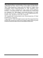
High Performance
K56Plus/V.34+/V.42bis
56K BPS
Plug & Play Internal
Voice/FAX/Data/SVD
Modem
With Advanced
Speakerphone functions
User's Manual
Contents
Section One - Introduction .......................... 1
Section Two - Installation ............................. 1
Section Three - AT Command Set ............... 7
Section Four - S Registers ........................ 14
Section Five - Result Codes ...................... 15
Section Six - Troubleshooting .................... 15
Section Seven - Support and Service ....... 16
Appendix A - Specifications ..................... 16
Appendix B - Notices ................................ 17
Part #MAN128 Rev. 1.0
K56Plus-L/CPI-SVD
The information contained in this manual has been
validated at the time of this manual's production.
The manufacturer reserves the right to make any
changes and improvements in the product described in this manual at any time and without
notice. Consequently the manufacturer assumes
no liability for damages incurred directly or indirectly from errors, omissions or discrepancies between the product and the manual.
All registered trademarks are the property of their
respective owners.
Copyright © 1997 All rights reserved. No reproduction
of this document in any form is permitted without prior
written authorization from the Manufacturer.
Section One - Introduction
This 56 Kbps* Plug and Play FAX/Voice/Data/
SVD Speakerphone Modem connects your computer
to all popular high speed modems available today. The
modem incorporates “K56Plus” (56Kbps) technology
to provide increased download speeds using regular
telephone lines. The modem incorporates Plug and
Play for ease of installation. It features speakerphone
capability for hands-free communication and full-duplex analog/digital simultaneous voice and data (SVD)
over a single telephone line.
This manual describes the hardware installation
procedures for your new modem. Additional information on AT commands and S-registers is provided so
that your system can be customized for a particular
operating environment.
*Note: K56Plus is capable of downloading at 56Kbps.
However, current FCC regulations limit its speeds to
53Kbps.
Section Two - Installation
This section will provide step by step instructions
on how to install your new 56 Kbps FAX/Voice/Data/
SVD modem. Installation of this modem product is a
three-step process consists of 1) actual hardware
installation, 2) plug and play configuration, and 3)
communication software installation and configuration.
2.1 Unpacking Your Modem
Be certain that you have all the items listed
below. This package contains:
• A modem
• A telephone cable
• User's manual
• Software for the modem
• Software user's manual
2.2 What You Need
You will need:
1. A phillips-head screw driver
2. A) A Plug and Play enabled Operating System
1
(e.g., Windows 95),
or
B) A Plug and Play Revision 1.0a compliant PC.
Proceed to Section 2.3 now if you have everything required.
If you have neither 2A or 2B above, youneed to
install Windows 95 to provide Plug and Play functionality to your PC.
2.3 Hardware Installation
Installation of this modem requires opening and
manipulating your PC. Exercise caution at all times
when working with AC powered and static-sensitive
equipment. Turn off and unplug your PC before installation. Discharge any static electricity from your body
by touching any bare metal surface of the PC system,
such as its power supply cover.
1. Turn off and unplug your computer from the AC
outlet.
2. Remove your computer's cover (refer to your
computer's owner's manual).
3. Select any available half-card slot, and then remove the slot cover (refer to Figure 2-1).
Figure 2-1 Expansion Slots
4. Carefully slide the internal modem into the slot
you have chosen, applying even pressure until
the modem is completely seated in the slot.
5. Fasten the retaining bracket with the screw from
the slot cover. Make sure the modem is properly
aligned. Store the slot cover for future use.
6. Replace the computer cover and plug in your
computer.
2
7. Connect the telephone cable from the modem's
LINE connector to the telephone wall jack.
8. Optionally, connect your telephone to the modem's
PHONE connector.
9. Turn your computer on. Your modem is now
installed.
2.4 Hardware Configuration (Plug and Play)
Your modem is configured using the Plug and
Play (PnP) capabilities of your computer. Plug and
Play is a set of specifications that define the ability for
the computer hardware and operating system to automatically configure all compliant devices that are installed, relieving the user of the need to determine
which addresses and interrupts to use for each device.
Consult your PC's owner's manual to determine if it is
PnP Revision 1.0a compliant. You most likely have a
Plug and Play Revision 1.0a compliant system if it was
purchased after June 1994 or if the BIOS is dated after
June 1994.
Proceed to one of the following sections, depending on your system's configuration:
• Section 2.4.1 if you are running Windows
95 (with or without a Plug and Play PC)
• Section 2.4.2 if you are running Windows
3.1x or DOS on a PnP-compliant PC.
2.4.1 Configuring in Windows 95
The version of Windows 95 you have will determine which set of dialog boxes is presented to you
when installing the modem in Windows 95. Proceed to
one of the following sections, depending on your
Windows 95's diaglog box:
• Section 2.4.1.1 when Windows 95 starts for
the first time after card installation, it
detects the modem and it displays the New
Hardware Found dialog box
• Section 2.4.1.2 when Windows 95 starts for
the first time after card installation, it
detects the modem and it displays the
Update Device Driver Wizard.
3
2.4.1.1
Windows 95 Release 4.00.950
When Windows 95 starts for the first time after
card installation, it detects the modem and displays the
New Hardware Found dialog box.
Under New Hardware Found, when asked to
“Select which driver you want to install for your new
hardware,” click on “Driver from disk provided by
hardware manufacturer.” Click “OK.”
The Install From Disk dialog box now instructs
you to “Insert the manufacturer's installation disk into
the drive selected, and then click OK.” Insert the
modem's driver diskette into the disk drive and type A:\
(or B:\ if inserted in drive B) in the “Copy manufacturer's
files from:” box. Click “OK.”
Windows 95 may request its own installation
disks or CD-ROM for some files. Insert the Windows
95 disks or CD-ROM as required. When all necessary
files are copied, the modem is configured. Windows 95
will assign the modem a COM port and IRQ line.
Proceed to Section 2.5.
2.4.1.2
Windows 95 Release 4.00.950 B
When Windows 95 starts for the first time after
card installation, it detects the modem and displays the
Update Device Driver Wizard.
Insert the driver disk into the disk drive and click
“Next.” Windows will find the driver on the driver disk.
Click “Finish. Windows 95 may request its own installation disks or CD for some files. Insert the Windows 95
disks or CD as required.
Windows will now find a second device on the
modem. Make sure that the driver disk is still in the disk
drive and click “Next.” Windows will find the second
driver. Click “Finish” to complete the installation.
When all necessary files are copied, the modem
is configured. Windows 95 will assign the modem a
COM port and IRQ line. Proceed to Section 2.5.
4
2.4.2 Configuring in a Plug and Play System without Windows 95
When this modem is installed in a Plug and Play
system without Windows 95, the computer's BIOS will
assign a COM port and IRQ line to the modem.
Proceed to Section 2.5, Software Installation/
Configuration.
2.5 Software Installation and Configuration
You are now ready to install and configure the
communication software. Refer to your software manual
for installation procedures.
We suggest the following communication parameters when you first use your data communication
software. Consult the software manual for information
on using these and other parameters/features.
57,600 bps; 8 data bits; no parity; 1 stop bit;
RTS/CTS flow control set to “on;” initialization
string: AT&F
We suggest that a “Generic Class 1” or “Generic Class 2” modem type should be selected in your
fax software, and a “Lucent” modem type should be
selected in your Voice software.
Note that your software must be configured to
communicate with the modem on the same COM port
and IRQ line used by the modem.
2.6 Using the Fax, Voice, SVD, and
Speakerphone Capabilities of the
Modem
Your modem has built-in advanced FAX, Voice,
SVD, and Full Duplex Speakerphone functions. Please
consult your FAX/Voice/SVD/Speakerphone software
manual about procedures on using these features.
Speakerphone functions require a correctly configured sound card with attached microphone and
speaker.
Voice functions include recording and playback
of voice prompts (files). You may record or playback
voice with your modem by attaching a telephone to the
5
RJ-11 jack marked “PHONE” or by attaching a microphone to the MIC jack and a speaker to the SPK jack
of your sound card. Follow instructions in the FAX/
Voice/Speakerphone software on recording and playback of voice prompts.
2.7 Testing Your Modem After Installation
In order to test your modem you should be
familiar with your communication software. Load and
set up your communication software and enter into
“terminal mode.” Make sure that the COM Port and
IRQ settings of the modem match the software. Type
AT on your terminal screen and press ENTER. You
may see “AT”, “AATT” or nothing on the screen. In any
case, the modem should respond with an OK or 0. If it
does not, either the modem may not have been installed properly or the software has not been properly
configured. Review Sections 2.2-2.5 and be certain
that the modem and the software have been properly
installed. If required, refer to Section 6 for additional
troubleshooting information.
2.8 Using Your Modem
The communication software included with your
modem product provides a user friendly interface to
access the fax, voice and data functions of your
modem. This software should be sufficient for all of
your communication needs. There may be times
when you need to access the modem manually via
modem commands. Read Section 3 for a summary
description of the modem command set before manually accessing the modem. You may want to read the
software manual first, however, as the software may
already provide a user friendly method of accessing
the functions you need (i.e. dialing or answering calls).
2.9 Where To Go From Here
You should familiarize yourself with the functions
available from the included software by reading its
manual. You will be accessing most, if not all, of the
modem's functions from this software. You may also
use any other commercially available communication
software with the modem. Read Section 3 only if you
6
are interested in accessing the modem manually, and
not through the included software. Section 4 and 5
contain reference material, and can be skipped. If you
have difficulties getting your modem to work, read
Section 6 - Troubleshooting to find answers to commonly asked questions and problems.
Section Three - AT Command Set
3.1 Executing Commands
Commands are accepted by the modem while it
is in Command Mode. Your modem is automatically in
Command Mode until you dial a number and establish
a connection. Commands may be sent to your modem
from a PC running communication software or any
other terminal devices.
Your modem is capable of data communication
at rates of: 300, 1200, 2400, 4800, 9600, 14400,
19200, 28800, 38400, 57600, and 115200 bps. Make
sure your COM port baud rate settings in your communications software is set to one of the above speeds.
3.2 Command Structure
All commands sent to the modem must begin
with AT and end with ENTER. All commands may be
typed in either upper or lower case, but not mixed. To
make the command line more readable, spaces may
be inserted between commands. If you omit a parameter from a command that requires one, it is just like
specifying a parameter of 0. Example:
ATH [ENTER]
This command causes your modem to hang up.
3.3 Basic AT Commands
In the following listings, all default settings are
printed in bold text.
Command
Function
A
Manually answer incoming call.
A/
Repeat last command executed. Do not
precede A/ with AT or follow with ENTER.
B_
B0
CCITT mode
7
B1
B2
B15
B16
Bell mode
V.23 originate mode @ 75 bps transmit/
1200 bps receive
V.23 originate mode @ 1200 bps
transmit/75 bps receive
Selects V.21 at 300 bps
Selects Bell 103 at 300 bps
L
P
T
W
,
@
!
;
0 - 9, A-D, # and *
last number redial
pulse dialing
touch-tone dialing
wait for second dial tone
pause
wait for five seconds of silence
flash
return to Command Mode after dialing
B3
D_
DS=n
E_
Dial one of the four telephone numbers
(n=0-3) stored in the modem’s nonvolatile memory.
E0
E1
+++
Commands are not echoed
Commands are echoed
Escape Characters - Switch from Data
Mode to Command Mode
H_
H0
H1
Force modem on-hook (hang up)
Force modem off-hook (make busy)
I_
I0
I1
I2
I3
I4
I9
Default speed and controller version
Display factory ROM checksum
Internal memory test
Default speed and controller version
Datapump firmware version
Country code
L_
L0
L1
L2
L3
Low speaker volume
Low speaker volume
Medium speaker volume
High speaker volume
M_
M0
M1
Internal speaker off
Internal speaker on until carrier
detected
Internal speaker always on
Internal speaker on until carrier detected
and off while dialing
M2
M3
N_
N0
N1
Disable Autoscan mode
Enable Autoscan mode
8
O_
O0
O1
Return to Data Mode
Return to Data Mode and initiate an
equalizer retrain
Q0
Q1
Modem sends responses
Modem does not send responses
P
Q_
Set Pulse dial as default
Sr?
Read and display value in register r.
Sr=n
Set register r to value n (n = 0-255).
T
Set Tone Dial as default
V_
V0
V1
Numeric responses
Word responses
W_
W0
W1
Report DTE speed only
Report line speed, error correction
protocol, and DTE speed.
Report DCE speed only
W2
X_
X0
X1
X2
X3
X4
X5
X6
X7
Y_
Y0
Y1
Z_
Z0
Z1
Hayes Smartmodem 300 compatible
responses/blind dialing
Display connect message according to
AT\V, blind dial, and ignore busy tone.
Same as X1 plus dial tone detection
Same as X1 plus busy detection/blind
dialing
All responses and dial tone and busy
signal detection
Same as X4
Same as X4
Same as X0 plus dial tone and busy
signal detection
Modem does not send or respond to
break signals
Modem sends break signal for four
seconds before disconnecting
Reset and retrieve active profile 0
Reset and retrieve active profile 1
3.4 Extended AT Commands
&C_
&C0
&C1
Force Carrier Detect Signal High (ON)
Turn on CD when remote carrier is
present
&D_
&D0
&D1
Modem ignores the DTR signal
Modem returns to Command Mode after
9
&D3
DTR toggle
Modem hangs up, returns to the
Command Mode after DTR toggle
Resets modem after DTR toggle
&F_
&F
Recall factory default configuration
&G_
&G0
&G1
&G2
Guard tone disabled
550 Hz guard tone
1800 Hz guard tone
&K_
&K0
&K3
Disable flow control
Enable RTS/CTS hardware flow
control
Enable XON/XOFF software flow control
Modem is set up for dial-up operation
&D2
&L_
&K4
&L0
&M_
&M0 Asynchronous operation
&S_
&S0
&S1
Force DSR Signal High (ON)
DSR off in command mode, on in on-line
mode
&T_
&T0
&T1
&T3
&T6
Ends test in progress
Perform Local Analog Loopback Test
Perform Local Digital Loopback Test
Perform a Remote Digital Loopback Test
&V
&V0
Displays Active Profile
&W_
&W0 Stores the active profile as Profile 0
&W1 Stores the active profile as Profile 1
&Y_
&Y0
&Zn=x
n=0-3 Store phone number x into non-volatile
RAM
%E_
%E0 Disable auto-retrain
%E1 Enable auto-retrain
%X_
%X0 Disable re--dialing suppression
%X1 Enables re-dialing suppression
#CID=n n=0
n=1
n=2
Configuration Profile 0 active upon
Power on or reset
Disable Caller ID
Enables Caller ID with formatting (date,
time, number, name)
Enables Caller ID without formatting
#CID?
Displays current Caller ID mode
#CID=?
Returns Caller ID capabilities of modem.
3.5 MNP/V.42/V.42bis Commands
%C_
%C0 Disable MNP Class 5 and V.42bis data
10
compression
%C1 Enable MNP Class 5 data compression
only
&Q_
&Q0
&Q5
&Q6
Direct data link only (same as \N1)
V.42 data link with fallback options
Normal data link only (same as \N0)
\A_
\A0
\A1
64-character maximum MNP block size
128-character maximum MNP block
size
192-character maximum MNP block size
256-character maximum MNP block size
\A2
\A3
\Bn
Send a 1/10 second line break to the modem,
where n = 1 to 9. At normal connect, the default
is 3
\J_
\J0
\J1
DTE speed is independent of modem
connect speed
DTE speed matches the modem connect
speed
\Kn
Set break control, where n= 0 to 5. The effect of
this command depends on the modem’s
operating condition. Default is 5.
\N_
\N0
\N1
\N2
\N3
\N4
\N5
\N7
Normal data-link only
Direct data-link only
MNP data link only
V.42/MNP/Normal data link
V.42 data link only
V.42/MNP/Normal data link
V.42/MNP/Normal data link
\Q_
\Q0
\Q1
\Q3
Disable flow control
XON\XOFF flow control
RTS\CTS flow control
\Tn
\V_
Inactivity timer (n=0-255 minutes)
\V0
\V1
\V2
\X_
\X0
\X1
Disable error correction protocol result
code
Enable error correction protocol result
code
Enable error correction protocol result
code
If XON/XOFF flow control is enabled,
do not pass XON/XOFF to remote
modem or local DTE
If XON/XOFF flow control is enabled,
11
pass XON/XOFF to remote modem or
local DTE
-C_
-C0
-C1
Data calling tone disabled
Data calling tone enabled
3.6 Fax Class 1 Commands
+FCLASS?
+FCLASS=?
+FCLASS=n
+FMI=?
+FMM=?
+FMR=?
+FRH=n
+FRH=?
+FRM=n
+FRM=?
+FRS=n
+FTH=n
+FTH=?
+FTM=n
+FTM=?
+FTS=n
Service class indication
Service class capabilities
Service class selection
Manufacturer identification
Product Identification
Version/Revision information
Receive data with HDLC framing
Receive HDLC data modulation
Receive data
Receive FAX modulation
Receive silence
Transmit data with HDLC framing
Transmit HDLC data modulation
Transmit data
Transmit FAX modulation
Stop transmission and wait
3.7 Fax Class 2 Commands
+FAA=n
+FAXERR
+FBOR
+FBUF?
+FCFR
+FCLASS=
+FCON
+FCIG
+FCIG:
+FCR
+FCR=
+FCSI:
+FDCC=
+FDCS:
+FDCS=
+FDIS:
+FDIS=
+FDR
+FDT
Adaptive Answer
Fax Error Value
Phase C Data Bit Order
Buffer Size
Indicate Confirmation to Receive
Service Class
Facsimile Connection Response
Set the polled station identification
Report the polled station identification
Capability to Receive
Capability to Receive
Report the Called Station ID
DCE Capabilities Parameters
Report Current Session
Current Session Results
Report Remote Identification
Current Sessions Parameters
Begin or Continue Phase C Receive
Data
Data Transmission
12
+FDTC:
+FET:
+FET=n
+FHNG
+FK
+FLID=
+FLPL
+FMDL?
+FMFR?
+FPHCTO
+FPOLL
+FPTS:
+FPTS=
+FREV?
+FSPL
+FTSI:
Report the polled station capabilities
Post Page Message Response
Transmit Page Punctuation
Call Terminations with Status
Session Termination
Local ID String
Document for polling
Identify Model
Identify Manufacturer
Phase C Time Out
Indicates polling request
Page Transfer Status
Page Transfer Status
Identify Revision
Enable polling
Report the Transmit Station ID
3.8 SVD Commands
-SAC
-SCD=
-SDA
-SDT
-SEM
-SER?
-SFA
-SFX
-SIC
-SIP
-SMD
-SMS=X,Y,Z,T
-SMT
-SNO
-SOR
-SQQ
-SQR=n
-SQS=X,Y
Accept Data mode request
Capabilities data
Start modem data mode
Date
Erase message
Error reporting
Facsimile data mode event message
Start facsimile data mode
Reset capabilities data to default settings
Initialize Voice View parameters
Modem data mode event message
Select ASVD/DSVD Mode. The X
parameter selects data, ASVD, DSVD or
automatic mode where 0=Data mode;
1=DSVD mode; 2=ASVD mode;
3=automatic mode select (default). Y,Z,T
are optional parameters to control
connection speeds.
Telephone handset mute control
Notification timer
Reject or overflow system messages
Start capabilities query
Capabilities query response control
Select ASVD modulation. Parameter X
selects the modulation mode where
0=V.61; 1=ML144; 2=ML288. The Y
parameter enables/disables ASVD
automatic modulation
13
-SRM
-SSE=n n=0
n=1
Retrieve message
Disable DSVD
Enable DSVD
-SSP
-SSR
-SSV
-STM
-STT
Set transmission speeds
Start sequence response control
Data mode event message
Time
Telephone handset transaction tone
control
Start Voice View data mode
-SVV
Section Four - S Registers
Your modem has 28 registers, designated S0
through S92. Table 4-1 shows the registers, their
functions, and their default values. Some registers can
have their values changed by commands. If you use a
command to change a register value, the command
remains in effect until you turn off or reset your modem.
Your modem then reverts to the operating characteristics specified in its non-volatile memory. Refer to
Section 3 for information on how to use the AT commands to manipulate the S registers.
Table 4-1 S - Registers
Register
S0
S1
S2
S3
S4
S5
S6
S7
S8
S10
S11
S12
S14
S21
S22
S24
S28
S30
S32
S33
S35
S36
Function
Range/units Default
Auto-answer Ring
0-255 /rings
0
Ring counter
0-255 /rings
0
Escape code character
0-127 /ASCII
43
Carriage return character
0-127 /ASCII
13
Line feed character
0-127 /ASCII
10
Backspace character
0-32, 127 /ASCII
8
Dial tone wait time
2-255 /seconds
2
Remote carrier wait time
1-255 /seconds
50
Comma pause time
0-255 /seconds
2
Carrier loss time
1-255 /0.1 second
14
Touch-tone dialing speed
50-255 /milliseconds 95
Escape character guard time 0-255 /0.02 second
50
Result codes, pulse dial
Bit mapped
8
DTR, DCD
Bit mapped
48
Result codes, pulse dial
Bit mapped
112
Sleep mode timer
0,5-255/seconds
10
V.34 modulation enable
0-255
1
Inactivity timer
0-255/minutes
0
Synthetic ring volume
- dB
10
Synthetic ring frequency
0-5
0
Data calling tone enable
0, 1
0
Negotiation failure fallback 0-7
7
14
S37
S38
S42-43
S48
S89
S90
S92
Connection speed
56K dial line rate
Reserved
LAPM negotiation
Sleep mode timer
Local phone status
Transmit level
0-19
0-16
0
1
7, 128
7
0, 5-255 seconds
10
0=on hook, 1=off hook
6-15/dB
15
Section Five - Result Codes
OK
0 CONNECT
1
RING
2 NO CARRIER
3
ERROR
4 CONNECT 1200
5
NO DIALTONE
6 BUSY
7
NO ANSWER
8 CONNECT 300 EC*
40
CONNECT 2400 EC*
10 CONNECT 4800 EC*
11
CONNECT 9600 EC*
12 CONNECT 7200 EC*
24
CONNECT 12000 EC*
25 CONNECT 14400 EC*
13
CONNECT 16800 EC*
86 CONNECT 19200 EC*
14
CONNECT 31200 EC*
83 CONNECT 21600 EC*
55
CONNECT 24000 EC*
56 CONNECT 26400 EC*
57
CONNECT 28800 EC*
58 CONNECT 31200 EC*
59
CONNECT 32000 EC*
70 CONNECT 33600 EC*
60
CONNECT 34000 EC*
71 CONNECT 36000 EC*
72
CONNECT 38400 EC*
28 CONNECT 38000 EC*
73
CONNECT 40000 EC*
74 CONNECT 42000 EC*
75
CONNECT 44000 EC*
76 CONNECT 46000 EC*
77
CONNECT 48000 EC*
78 CONNECT 50000 EC*
79
CONNECT 52000 EC*
80 CONNECT 54000 EC*
81
CONNECT 56000 EC*
82 CONNECT 57600 EC*
18
CONNECT 58000 EC*
83 CONNECT 60000 EC*
84
CONNECT 115200 EC*
87
* EC denotes one of the following extensions depending on the
error control method used when extended result codes are
enabled.
V42bis - V.42 error correction and B.42bis data compression
V42 - V.42 error correction only
MNP 5 - MNP Class 4 error correction and MNP Class 5 data
compression
MNP 4 - MNP Class 4 error correction only
NoEC - Error correction is off
Section Six - Troubleshooting
This section describes some of the common
problems you may encounter while using your modem.
If you can not resolve your difficulty after reading this
chapter, contact your dealer or vendor for assistance.
Modem does not respond to commands.
1. Make sure the communication software is configured
15
.2
hm
te
oto
ka”td
l“o
etm
h
o
ctC
e
o
nrcO
tM
ap
R
nIod
trQ
n
s(a
sg
ie
m
ttC
eOM
ap
R
nIod
th
rQ
n
m
a
tse
g
isttodem
Yo
c.o
)um
r muo
cn
sw
a
n
io
tfa
m
erku
nsotwch
aidderyso
m
su
R
IrS
oQ
n
m
yh
d
a
s,g
im
tle
yr.u
n
sp
e
o
ctm
sive
cd
rb
m
a
n
g
itso
rfu
ye
d
a
h
im
rtslca
e
rtodem.
MY
ya
zm
h
o
e
skctyia
u
e
o
d
.rtlciro
tndiesm
im
e
sd
ra
p
n
sizyp
o
le
h
a
to
id
a
yn
lb
ivY
se
tno
e
ism
.u
na
h
m
o
fa
ce
tyr-seo
tdesm
n
iu
b
A
g
iyT&aF
n
pe
d
rE
sNTE
oT
w
h
la
m
R
td
e
h
lo
fce
sya
t.rfu
olde
sd
ra
p
m
so
iyp
ltcoa
nm
e
sa
e
trfsman
hd
b
ae
sen
xecu
etd.
Mod
.e
a
m
d
lin
oo
es
t
.1
.2
Mah
skm
tu
erodceosm
nin
w
a
eoe
co
n
tp
kd
R
rg
ih
no
e
in
.la
p
h
m
etcleodew
m
aw
ho
n
tp
krg
ihw
e
o
h
p
sn
te
h
n
so
ietku
a
o
e
irgtn
.le
Mach
ksp
o
e
tu
se
h
n
riao
n
e
im
h
cjn
te
klo
e
cta
dkrL
e
N
“nIdco
E
er”n
ct.no
e
pe
n
icrtvhm
e
tn
stodeo
m
rm
fopn
e
p
m
S
R
a
o
g
irtp
o
fe
ry2
3
e
.n
o
iclfrtdem
conno
ure
sin
ctist.
Mo
d
cd
b
o
n
e
u
n
o
m
sa
tn
d
le
i.ct
.1
.2
Md
o
h
b
a
m
te
R
n
ico
h
ksa
In
te
u
iln
tQ
riosg
id
e
te
tm
ahsn
w
te
od
M
faer.odem
answ
d
o
tfm
aerbcu
e
o
gsd
n
u
itye
ficr.ld
a
n
ilt
Maksh
e
u
p
tw
erh
sno
ie
nkp
rlg
io
R
e
rpye
.lra
phclm
teodem
e
ra
w
g
p
hta
u
hirlon
h
sn
a
te
io
h
u
n
lta
d
e
m
n
lid
fn
yIso
b
m
yu
ie
,.rco
a
ychtu
n
yiah
lfe
n
rvtfd
e
o
m
nitg
ctd
oetcve
i.
Modem
m
co
ak
a
n
d
e
p
n
s
a
b
o
p
y
e
ts
u
n
io
c
e
a
ts
ru
n
r.
.1
.2
Makse
h
utce
ro
d
e
o
rafm
ca
rsn
lw
to
b
)fcp
td
R
y,(o
ista
b
,n
o
irtT
lSC
/Ta
S
be
re
n
)u
igsed.
M
em
e
trh
a
cm
n
e
o
stkru
a
e
co
m
itrln
a
iu
btn
u
le
so
g
sie
d
(co
d
emmw
u
o
sco
tn
a
im
fa
teranu
.)al
he
s
o
w
a
H
tc
d
in
rg
p
th
e
iheny
eo
v
ae
n
u
rsp
h
w
th
eo
erne.
.1
MaskA
u
erY
u
oA
t-m
o
unt.u
re
o
fsrd
w
o
fa
icd
N
g
o
fcye
u
tn
rie
sm
rO
fd
iaT
u
oat-nsIw
u
A
eeT
y.m
a
ros&
fcu
e
yto
rto
F
dem.
Modc
eo
m
e
w
m
x
e
p
o
n
e
s
lrm
ic
h
re
im
s
ao
e
h
w
n
tu
o
g
c
in
d
atiem.
.1
.2
.3
.4
M
D
ha
e
tskh
u
e
T
artm
sE
h
pse
taie
so
ddem
consn
ope
niM
cw
e
tD
d
rn
co
h
tid
ee
n.
M
erh
m
ae
tsku
e
srye
o
sm
tam
ynodurodem
shu
ae
tsm
ecoemmp
o
u.ca
n
)ice
rim
.tsyp
(,tp
esa
e
rtird,
MasR
ku
erTS
C
/Teh
S
n
sado
rie
a
w
bcd
ln
X
o
fd
a
n
re
O
lrtN
h
X
co
t/em
sn
O
d
ae
isbd
lF
o
m
iw
scF
lo
tfo
a
n
rw
u
e
o
slrco
tn
a
ifa
ter.
M
htayh
d
csko
n
e
ftu
a
p
te
rm
tM
o
e
srte
B
icIyd
a
p
.tM
o
sp
u
e
sci'a
to
rlb
m
ica
e
b
p1
rsla
p
i9
2
ta
o,0
e
b
f0
u
p
ln
sD
deO
ra
S
n
W
dnd
iow
O
3
X
g
h
.sp
h
.in
a
eg
a
itre
tu
dn
sW
dernd
ioC
w
a
er4
fsq
a
e
tP
8
rso
u
W
s6
riU
ornd
iow
95
s.
Mods
eu
m
e
o
d
x
o
re
s
d
p
rc
n
e
io
y
n
b
rce
lu
c
fs
n
w
o
rte
m
s
clh
tim
erm
am
u
w
n
h
c
o
n
e
tg
ia
tiodem.
.1 Maksu
e
W
C
tn
rese
n
.o
ia
fld
gfa
tli
2. Make sure the phone line does not exhibit excess
noise.
Section Seven - Support and Service
In the unlikely event you experience difficulty in
the use of this product, we suggest you: (1) consult the
Troubleshooting section of this guide and (2) consult
with your dealer. To obtain service for this product,
follow the Return Merchandise Authorization Procedure as outlined in the Warranty card.
Appendix A - Specifications
Communication Std.
Data Compression:
Error Correction:
Host Interface:
K56Plus (56Kbps), V.34,
V.32bis, V.32, V.29, V.27ter,
V.22bis, V.23, V.22, V.21, V.17,
Bell212/103
V.42bis/MNP5
V.42/MNP2-4
16 bit PC bus
16
C
:sO
tp
M
o
r
IRQ lines:
FAX Group:
4321,,
3, 4, 5, 7, 9, 10, 11, 12, 15
Group III Send/Receive
Standard
FAX Command set: EIA/TIA-578 Service Class 1,
EIA/TIA-SP2388 Service Class
2
Transmit level:
-11 dBm +/- 1 dB
Receiver Sensitivity: -39 dBm (V.34); -43 dBm (all
other protocols)
UART:
16550 compatible
Data format:
300-115200 bps
Power:
0.75 W
T
e
m
:u
ra
tp
e
r
5
do
5
etge
0
O
rC
(esp
ne
g
a
ir)t
Caller ID:
Yes
PnP:
Revision 1.0a
Speakerphone:
Full-duplex with DSP echo
cancellation
Appendix B - Notices
FCC Compliance
This equipment complies with Part 68 of the FCC Rules. On
this equipment is a label that contains, among other information, the FCC registration number and Ringer Equivalence
Number (REN) for this equipment. You must, upon request,
provide this information to your telephone company.
If your telephone equipment causes harm to the telephone
network, the Telephone Company may discontinue your
service temporarily. If possible, they will notify in advance.
But, if advance notice is not practical, you will be notified as
soon as possible. You will be informed of your right to file a
complaint with the FCC.
Your telephone company may make changes in its facilities,
equipment, operations, or procedures that could affect proper
operation of your equipment. If they do, you will be notified in
advance to give you an opportunity to maintain uninterrupted
telephone service.
The FCC prohibits this equipment to be connected to party
lines or coin-telephone service.
In the event that this equipment should fail to operate
properly, disconnect the equipment from the phone line to
determine if it is causing the problem. If the problem is with the
equipment, discontinue use and contact your dealer or vendor.
17
ThF
eCC
e
a
sro
a
q
lrhF
e
tn
u
rasA
iom
a
e
rftX
n
rtsim
so
sb
in
pe
d
p
o
F
(rid
e
pfC
yn
reiltrC
Ru
e
P
S
6ls8
6
a
e,t8
3
rc(.)8
c()1
em
S
F
atB
C
C
as
C
en
lt
Teh
sqiu
pime
hn
abtseetn
setadn
ofd
ucn
otC
d
am
o
afe
la
risB
h
p
d
g
ctw
vslh
e
u
p
iyts,rlh
iu
P
tF
o
1
e
a
to5
C
a
n
ftrC
RT
u
elshm
.a
ed
ise
rtleig
sinp
e
otrdve
rieasonap
b
eo
re
lota
cintgh
a
na
isn
m
treitfe
ro
T
n
ru
a
d
e
fin
sa
lh
tcsie
q
.la
in
u
p
iltime
gn
etnea
u
retse
,asncdarn
e
a
d
re
fq
d
io
tu
iencen
yen
ia
sld
e
to
n
a
lg
ru
ftd
n
ysia
,d
n
ecid
cod
rann
h
cw
tu
ise
o
rhtm
cintis,acyaushean
m
reitfe
ru
n
a
fro
lcd
to
eimmun
coa
iH
nts.own
h
eg
sto
e
viu
e
rh
sa
,q
tria
ru
p
ne
ifm
h
to
Ie
n
ra
p
cin
sa
lo
ctu
i.ce
d
ltw
ru
en
o
lrte
icsaushean
m
reitfe
re
u
n
a
tfro
sle
vcrd
o
itn
e
crieo
w
pint,h
ch
iabn
deetm
rnieu
btd
n
h
ryte
igqu
pim
an
h
e
o
tu
fsd
e
n
fsicte
,oru
cn
h
o
e
a
tire
fyrgcn
te
otcde
ow
lo
m
b
n
h
fln
yto
g
e
ie
roe
frasuers:
•
R
o
e
h
rcltn
e
a
o
ve
g
in
tro
eitrnna
• Increase the separation between the equipment and the
receiver
• Connect the equipment into an outlet on a circuit different
from that to which the receiver is connected
• Consult the dealer or an experienced radio / TV technician
for help
Notice: 1) Shielded cables, if any, must be used in order to
comply with the emission limits. 2) Any change or modification not expressly approved by the Grantee of the equipment
authorization could void the user’s authority to operate the
equipment.
DOC Compliance Information
NOTICE: The Canadian Department of Communications
label identifies certified equipment. This certification means
that the equipment meets certain telecommunications network protective, operational and safety requirements. The
Department does not guarantee the equipment will operate to
the user’s satisfaction.
Before installing this equipment, users ensure that it is
permissible to be connected to the facilities of the local
telecommunications company. The equipment must also be
installed using an acceptable method of connection. The
customer should be aware that compliance with the above
conditions may not prevent degradation of service in some
situations.
Repairs to certified equipment should be made by an authorized Canadian maintenance facility designated by the supplier. Any repairs or alterations made by the user to this
equipment, or equipment malfunctions, may give the telecommunications company cause to request the user to
disconnect the equipment.
Users should ensure for their own protection that the electrical ground connections of the power utility, telephone lines
and internal metallic water pipe system, if present, are
connected together. This precaution may be particularly
important in rural areas.
Caution: Users should not attempt to make such connections themselves, but should contact the appropriate electric
nispe
oa
ce
in
a
o
tiu
ln
csrh
p
yt,o
pio
ra
peitr.
18
NOTC
IT
E
hL:eoaN
dumL
b
(N
a
esrgs)n
ieo
e
a
te
d
cm
trhdnea
icd
ve
linh
o
p
e
to
b
e
sco
a
le
rtd
o
n
h
ate
n
ltgp
e
lo
ao
e
h
cftd
ono
lw
e
u
psh
e
cp
id
b
to
h
e
d
irtyvco
eivn
o
,eta
lrT
n
de
g
ihm
tr.eo
n
ola
im
np
tacn
co
yo
yn
fsm
tidn
b
o
ea
ich
n
e
vrftsie
q
o
u
se
tru
e
bm
yn
icjh
ltsh
e
ute
L
a
m
n
o
ttafN
dh
ud
te
m
cve
d
ilab
sole
nsfrxoctee1d00.
c
eN
U
io
L
t
Cau
n
m
o
eT
n
itrn
a
shlo
:iU
d
ne
sL
cn
itL
d
o
b
ilm
a
so
m
te
lad
sa
ip
A
w
p
o
e
utlysn
r,a
lsd
ycsionhm
n
teco
tdem
ad
ore
a
m
fhtp
leh
tronse
yw
so
tm
a
n
ie
rh
dtn
la
sm
ice
utg
io
ln
rive
oro
ve
m
fhcd
te
ompu
e.tr
o
E
n
istF
d
ri
G
0
V
1o
.Z
D
n
e
si/r-R
19
20
21