1
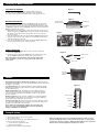
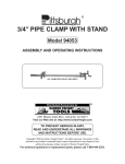
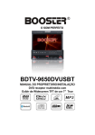
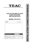
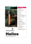
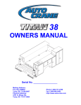
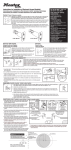
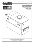
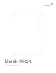
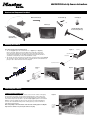
4843DATSEN Back-Up Camera Instructions
Hardware and Components Included:
Wireless Antenna (1)
Vent Clip (1)
Power Cable (1)
Monitor (1)
Flexible Mounting Arm
w/ Suction Cup Base (1)
Camera with
Guide/Hood (1)
Mounting the Camera:
The camera has two basic mounting options:
1. The camera (figure 1) can be mounted inside a 1 ¼” (figure 2) or 2” (figure 3)
hitch receiver tube. Slide the camera assembly into the hitch tube. The magnet
in the camera base will hold it securely in place, however the plastic guide on the
camera bracket will help line the assembly up with the hitch pin opening and allow
a standard or locking hitch pin to be used for additional security.
2. The camera can also be mounted to any metal surface using the magnetic base. (figure 4)
The soft pads on the base will prevent sliding or scratching and the camera bracket can
pivot up to 90° to allow the field of view to be adjusted.
Figure 1
Transmitter Housing
Guide/Hood
Pass thru/T-connector
Figure 2
Figure 3
1-1/4" Tube
2" Tube
Figure 4
Connecting the Camera:
CAMERA POWER CONNECTION
The camera is powered by plugging the camera connector into the vehicle’s towing plug.
The camera has a 4 position connector which will attach directly to many vehicles and
has a pass-though design that will allow it to be plugged between the vehicle and trailer.
Some vehicles may need a 7 position to 4 position adapter (figure 5) which is not included.
Figure 5
NOTE: A commonly available 4 position tow wire extension (not included) will allow the
camera to be mounted farther away from the vehicle plug for gooseneck or fifth wheel
trailer hitching up applications.
Notice: Depending on the make/model of the vehicle the running lights or headlights
may need to be turned on to power up the vehicle’s tow plug.
7 Position
to 4 Position
Adapter
Shown
Antenna
Connecting the Monitor and Antenna:
Figure 6
ATTACHING THE ANTENNA
The wireless antenna (figure 6) attaches to the threaded connector on
the back of the monitor (figure 7). Once attached, it can be rotated 360°
as needed to find the position which give the best reception from the camera.
Figure 7
MOUNTING THE MONITOR
When choosing a location to mount the monitor (figure 7), make sure the monitor
is in an area that will not obstruct your vision while driving or interfere with access
to any of the vehicle controls. It can be placed on the windshield using the mounting
arm (figure 8) or clipped to an air vent (figure 9). Both options use the mounting slot
(figure 7) on the back of the monitor.
1. Temporarily place the monitor stand or clip in the location that you have chosen
and route the power cable (figure 10) to the vehicle’s 12V power outlet and verify
the cable does not interfere with the safe operation of the vehicle or access to
any vehicle controls.
2. To use the mounting arm, slide it into the mounting slot (figure 7) and remove the
vinyl protector from the base, place it firmly on a smooth surface and rotate the
small cam near the base of the arm.
3. To use the vent clip, slide it into the monitor mounting slot (figure 7) and gently
press the clip and monitor over the vehicle air vent fins.
Mounting Slot
Threaded Wireless
Antenna Connector
Power Button
(On/Off)
Figure 8
Figure 9
Mounting Arm
Vent Clip
POWER CONNECTION
1. Insert the small DC plug (figure 10) of the power cable into the right side
of the monitor (figure 12).
2. Insert the larger 12 Volt power plug (figure 10) into the vehicle power socket.
The red LED (figure 11) will come on if the vehicle socket has power.
Figure 10
12 Volt Power Plug
Notice: Depending on the make/model of the vehicle the ignition may
need to be turned on or to the accessory position for the 12V socket
to have power.
DC Plug
Power Cable
Figure 11
Power and
Channel LED
Indicator
Controls:
3.5" LCD TFT Display, 480x243
Blue LED Power and Wireless Channel Indicator (figure 11) - When the monitor
is ON the blue LED will be lit. The location of the blue LED also indicates what channel
the display is set to display.
Power Button (figure 7)- Press the Power button to turn the display ON, the blue
LED will be lit to indicate the monitor is ON. Press it again to turn the display OFF,
the blue LED will turn off.
Wireless Channel (figure 12) – This display can accept 4 different channels of
wireless transmission. To change the channel press the “CH” button and it will
go to the next channel after channel 4 it will return to channel 1. The camera is
pre-set to channel 4.
Brightness (figure 12) - There are 6 levels of brightness. To adjust the brightness,
press the Brightness Control button. Press the button to increase the brightness,
after the highest level it will return to the lowest level.
Contrast Control (figure 12) - There are 6 levels of contrast. To adjust the contrast,
press the Contrast Control button. Press the button to increase the contrast, after
the highest level it will return to the lowest level.
Notice: Under extreme bright light conditions, the screen image may
take a few seconds to automatically adjust. It is best to wait until the
image has stabilized before backing up.
Figure 12
Wireless Channel
No Function
Brightness
Contrast
DC Input
Testing the System:
1. Turn the vehicle ignition to the accessory position.
Do not start the vehicle.
2. Turn on the monitor and the blue status LED should come on.
3. If there is no picture on the display.
a. Set the monitor to channel 4 if needed.
b. Turn on the vehicle lights.
4. Adjust the monitor antenna for the best picture.
Notice: Re-locating the monitor even a small amount inside the vehicle can affect
the picture quality. This device, as well as all other wireless devices, may be subject
to interference caused by cell phones, Bluetooth headsets, Wi-Fi routers, power lines
and other various electrical equipment, including other cameras.
Warning:
This device complies with part 15 of the FCC Rules. Operation is subject to the following two conditions: (1) This device may not cause harmful
interference, and (2) this device must accept any interference received, including interference that may cause undesired operation. Changes or
modifications not expressly approved by the party responsible for compliance could void the user’s authority to operate the equipment.
IMPORTANT SAFETY INSTRUCTIONS
PLEASE READ THIS OWNER’S MANUAL CAREFULLY BEFORE INSTALLING AND USING YOUR CAMERA.
RETAIN THIS MANUAL FOR FUTURE REFERENCE.
Do not use this camera as a substitute for rear view mirrors, side view mirrors, or for any other motor vehicle equipment mandated
by law.
This product does not relieve vehicle operators of their responsibility to insure they can safely back up their vehicle.
Back-up cameras have a limited field of vision and do not provide a comprehensive view behind the vehicle. Accordingly, use this
camera only as a supplement to mirrors and your own eyesight to determine if it is safe to back up. Do not back up until you are sure
it is safe to do so. Back up as slowly as possible, to allow for maximum reaction time to stop the vehicle if you detect an obstacle.
Due to the camera’s wide angle lens, objects shown in the monitor are closer than they appear
The picture in the monitor screen is a mirror image, just like the view from your rear view mirror.
The camera will not show objects which have just moved out of, or are just moving into, the range of the camera’s lens, or objects
that are close to either corner of the bumper or under the bumper, or behind the camera’s lens.
The camera works best in bright light, and its ability to show the area behind the vehicle is diminished at night, or in dark areas. The
vehicle’s back-up lights will provide light to help the camera show the area behind the vehicle at night or in dark areas. Do not use
the camera unless those lights are working.
Keep the camera lens free of water, water spots, snow, ice and dirt so the video image remains clear and undistorted. Clean the lens
with a soft, lint-free cloth and non-abrasive cleaner. If the camera system image is not clear or seems distorted, clean the camera
lens before further use.
Remove the camera from its installation before washing the vehicle
Use For Hitch Alignment and Towing:
Before towing, confirm your vehicle and trailer are compatible, hooked up and loaded properly and that you have any necessary
additional equipment. The camera will only show the relative position of the vehicles and their towing attachments. After aligning
the vehicles with the camera, visually confirm that the towing configuration is secure.
Do not use the camera view as a subsitute for recommended periodic inspection of the towing configuration during use.
When towing, the camera system will only show the front of the towed vehicle. Be sure that your towing vehicle and towing
configuration is equipped with appropriate mirrors and other vision aids to allow you to see behind the towed vehicle.
ONE YEAR LIMITED WARRANTY: If this product fails due to a defect in materials or workmanship within one year of purchase, Master Lock
Company LLC will replace it free of charge, with proper proof of purchase. Simply contact Master Lock at www.masterlock.com for replacement
information. This warranty does not cover products which have been abused, altered, damaged, misused, cut or worn. TO THE EXTENT
PERMITTED BY LAW, MASTER LOCK COMPANY LLC DISCLAIMS ALL OTHER IMPLIED OR EXPRESS WARRANTIES INCLUDING ALL
WARRANTIES OF MERCHANTABILITY AND/OR FITNESS FOR A PARTICULAR PURPOSE.
LIMITATION OF LIABILITY: This warranty is your sole remedy and MASTER LOCK COMPANY LLC shall not be liable for any damages, whether
direct, indirect, incidental, special, consequential, exemplary, or otherwise, including property damage, lost revenues and lost profits, arising out
of any theory of recovery, including statutory, contract or tort. Notwithstanding the term of any limited or implied warranty, or in the event that any
limited warranty fails of its essential purpose, in no event will MASTER LOCK COMPANY LLC’s entire liability exceed the purchase price of this
product. Some states and provinces do not allow the exclusion or limitation of incidental or consequential damages so the above limitations or
exclusions may not apply to you. This limited warranty gives you specific legal rights, and you may also have other rights which vary from state to
state and province to province.
w ww.maste r l o c k.c o m
Master Lock Company LLC, Milwaukee, WI 53154 U.S.A. | 800-308-9244
Master Lock Canada, Oakville, Ontario L6H 5S7 Canada | 800-227-9599
© 2009 Master Lock Company | All Rights Reserved
104115
104835
02/09