1
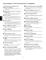
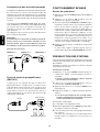
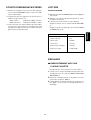
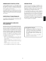
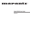
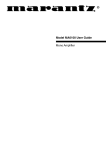
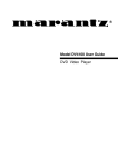
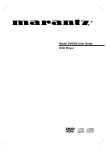
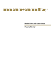
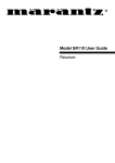
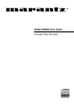
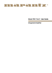
Model SR4120 User Guide
Receiver
1
CAUTION
RISK OF ELECTRIC SHOCK
DO NOT OPEN
CAUTION: TO REDUCE THE RISK OF ELECTRIC SHOCK,
DO NOT REMOVE COVER (OR BACK)
NO USER-SERVICEABLE PARTS INSIDE
REFER SERVICING TO QUALIFIED SERVICE PERSONNEL
The lightning flash with arrowhead symbol, within
an equilateral triangle, is intended to alert the user
to the presence of uninsulated “dangerous voltage”
within the product’s enclosure that may be of sufficient magnitude to constitute a risk of electric shock
to persons.
The exclamation point within an equilateral triangle
is intended to alert the user to the presence of
important operating and maintenance (servicing)
instructions in the literature accompanying the
appliance.
WARNING
TO REDUCE THE RISK OF FIRE OR ELECTRIC SHOCK,
DO NOT EXPOSE THIS APPLIANCE TO RAIN OR MOISTURE.
CAUTION: TO PREVENT ELECTRIC SHOCK, MATCH WIDE
BLADE OF PLUG TO WIDE SLOT, FULLY INSERT.
ATTENTION: POUR ÉVITER LES CHOCS ÉLECTRIQUES,
INTRODUIRE LA LAME LA PLUS LARGE DE LA FICHE DANS LA
BORNE CORRESPON-DANTE DE LA PRISE ET POUSSER
JUSQU’AU FOND.
2
SAFETY
INSTRUCTIONS
READ BEFORE OPERATING EQUIPMENT
This product was designed and manufactured to meet strict
quality and safety standards. There are, however, some installation and operation precautions which you should be
particularly aware of.
12. Grounding or Polarization — The precautions that
should be taken so that the grounding or polarization
means of an appliance is not defeated.
1. Read Instructions — All the safety and operating instructions should be read before the appliance is operated.
2. Retain Instructions — The safety and operating instructions should be retained for future reference.
AC POLARIZED PLUG
13. Power-Cord Protection — Power-supply cords should
be routed so that they are not likely to be walked on or
pinched by items placed upon or against them, paying
particular attention to cords at plugs, convenience receptacles, and the point where they exit from the
appliance.
3. Heed Warnings — All warnings on the appliance and in
the operating instructions should be adhered to.
4. Follow Instructions — All operating and use instructions should be followed.
5. Water and Moisture — The appliance should not be
used near water — for example, near a bathtub, washbowl, kitchen sink, laundry tub, in a wet basement, or
near a swimming pool, etc.
14. Cleaning — The appliance should be cleaned only as
recommended by the manufacturer.
15. Power Lines— An outdoor antenna should be located
away from power lines.
6. Carts and Stands — The appliance should be used
only with a cart or stand that is recommended by the
manufacturer.
16. Outdoor Antenna Grounding — If an outside antenna is
connected to the receiver, be sure the antenna system
is grounded so as to provide some protection against
voltage surges and built up static charges. Section 810
of the National Electrical Code, ANSI/NFPA No. 701984, provides information with respect to proper
grounding of the mast and supporting structure,
grounding of the lead-in wire to an antenna discharge
unit, size of grounding conductors, location of antennadischarge unit, connection to grounding electrodes, and
requirements for the grounding electrode. See Fig. 1.
7. An appliance and cart combination should be moved
with care. Quick stops, excessive force, and uneven
surfaces may cause the appliance and cart combination to overturn.
17. Nonuse Periods — The power cord of the appliance
should be unplugged from the outlet when left unused
for a long period of time.
8. Wall or Ceiling Mounting — The appliance should be
mounted to a wall or ceiling only as recommended by
the manufacturer.
18. Object and Liquid Entry — Care should be taken so that
objects do not fall and liquids are not spilled into the enclosure through openings.
9. Ventilation — The appliance should be situated so that
its location or position does not interfere with its proper
ventilation. For example, the appliance should not be
situated on a bed, sofa, rug, or similar surface that may
block the ventilation openings; or, placed in a built-in
installation, such as a bookcase or cabinet that may
impede the flow of air through the ventilation openings.
19. Damage Requiring Service — The appliance should be
serviced by qualified service personnel when:
A. The power-supply cord or the plug has been damaged; or
B. Objects have fallen, or liquid has spilled into the appliance; or
C. The appliance has been exposed to rain; or
10. Heat — The appliance should be situated away from
heat sources such as radiators, heat registers, stoves,
or other appliances (including amplifiers) that produce
heat.
D. The appliance does not appear to operate normally
or exhibits a marked change in performance; or
E. The appliance has been dropped, or the enclosure
damaged.
11. Power Sources — The appliance should be connected
to a power supply only of the type described in the operating instructions or as marked on the appliance.
20. Servicing — The user should not attempt to service the
appliance beyond that described in the operating instructions. All other servicing should be referred to
qualified service personnel.
3
FIGURE 1
EXAMPLE OF ANTENNA GROUNDING ACCORDING TO
NATIONAL ELECTRICAL CODE INSTRUCYIONS
CONTAINED IN ARTICLE 810 -"RADIO AND TELEVISION EQUIPMENT"
ANTENNA LEAD
IN WIRE
GROUND CLAMP
ANTENNA
DISCHARGE UNIT
(NEC SECTION 810-20)
ELECTRIC
SERVICE
EQUIPMENT
GROUNDING CONDUCTORS
(NEC SECTION 810-21)
GROUND CLAMPS
POWER SERVICE GROUNDING
ELECTRODE SYSTEM
(NEC ART 250, PART H)
NEC - NATIONAL ELECTRICAL CODE
NOTE TO CATV SYSTEM INSTALLER:
This reminder is provided to call the CATV (Cable-TV) system installer's attention to Article 820-40 of the NEC,
which provides guidelines for proper grounding and, in particular, specifies that the cable ground shall be
connected to the grounding system of the building, as close to the point of cable entry as practical.
NOTE:
This equipment has been tested and found to comply
with the limits for a Class B digital device, pursuant to
Part 15 of the FCC Rules. These limits are designed
to provide reasonable protection against harmful interference in a residential installation. This equipment
generates, uses and can radiate radio frequency
energy and, if not installed and used in accordance
with the instructions, may cause harmful interference
to radio communications. However, there is no guarantee that interference will not occur in a particular
installation. If this equipment does cause harmful
interference to radio or television reception, which
can be determined by turning the equipment off and
on, the user is encouraged to try to correct the inter-
ference by one or more of the following measures:
– Reorient or relocate the receiving antenna.
– Increase the separation between the equipment
and receiver.
– Connect the equipment into an outlet on a circuit
different from that to which the receiver is connected.
– Consult the dealer or an experienced radio/TV
technician for help.
This Class B digital apparatus complies
with Canadian ICES-003.
Cet appareil numérique de la Classe B est
conforme à la norme NMB-003 du Canada.
NOTE:Changes or modifications may cause this
unit to fail to comply with Part 15 of the FCC Rules
and may void the user's authority to operate the
equipment.
4
q
u
y
!5
i
RECEIVER SR4120
VOLUME
TUNING/PRESET
DOWN
UP
TAPE MONI
AUX
CD
PHONO
FM/AM
MIN
MAX
STANDBY
BASS
POWER
TREBLE
BARANCE
ON/STANDBY
PHONES
1
SPEAKERS
2
F/P
-
o !0
!1
+
-
!2
b
+
L
!3
P.SCAN
!4
w e r t
e
g
c d
f
A
J
ANTENNA
AM
SPEAKER SYSTEMS
SYSTEM 1
: MINIMUM 8 OHMS
SYSTEM 2
: MINIMUM 8 OHMS
SYSTEM2
R
L
FM
(75‰)
AC OUTLETS
120V 60Hz
PHONO
CD
TAPE
AUX
PRE OUT
REMOTE
CONTROL
L
IN
R
OUT
RESET
R
IN
OUT
BE D CG F
SWITCHED
TOTAL 120W 1A
L
SYSTEM1
H
I
5
FM MODE
R
a
GND
MEMO
ENGLISH
FOREWORD
PRECAUTIONS
This section must be read carefully before any
connection is made to the mains supply.
The following precautions should be taken when
operating the equipment.
WARNINGS
GENERAL PRECAUTIONS
¡ Do not expose the equipment to rain or moisture.
¡ Do not remove the cover from the equipment.
¡ Do not insert anything into the equipment through
the ventilation holes.
¡ Do not handle the mains lead with wet hands.
When installing the equipment ensure that:
– the ventilation holes are not covered.
– air is allowed to circulate freely around the
equipment.
– it is placed on a vibration-free surface.
– it will not be exposed to excessive heat, cold,
moisture or dust.
– it will not be exposed to direct sunlight.
– it will not be exposed to electrostatic discharges.
– always install the unit horizontally.
INTRODUCTION
Thank you selecting the Marantz receiver for your
system.
This receiver incorporates a number of features
designed to enhance the listening of your favorite
music.
Please read these operating instructions carefully. We
recommend that you read the entire user guide before
you attempt to connect or operate the receiver.
After you have reviewed the contents of this manual,
We recommend that you make all system connections
before you attempt to operate the unit.
In addition, never place heavy objects on the
equipment.
If a foreign object or water does enter the equipment,
contact your nearest dealer or service center.
Do not pull out the plug by pulling on the mains lead;
grasp the plug itself.
it is advisable when leaving the house, or during a
thunderstorm, to disconnect the equipment from the
AC outlet.
Refer to the figures on the page 5. The call out numbers
on the figures correspond to those found in the text.
All references to the connections and controls that are
printed in BOLD type are as they appear on the unit.
FEATURES
¡ Equipped with 4 audio inputs.
¡ FTC 55 watt x2 output power.
¡ Full discrete main amplifier.
¡ FM/AM each 30-stations random preset memory.
INSTALLATION
Remember the following important points when
installing the receiver.
¡ Do not expose the component to rain or moisture,
as this may cause damage to the receiver.
¡ All receivers produce some heat during operation
and this heat must be allowed to disperse freely.
Do not close any ventilation openings and insure
that there is adequate ventilation space behind,
beside and above the receiver.
¡ Prevent extra heat from reaching the unit. Never
put the receiver in the full glare of the sun or near a
heat source.
6
LOCATION AND FUNCTION OF PARTS AND CONTROLS
!3 TREBLE CONTROL knob
Front panel Features
Adjust the high frequency level with this control
according to your taste and room acoustics.
q STANDBY indicator
This indicator lights up when in the standby mode.
Adjust the sound volume between left and right
speakers with this control knob.
This use the display mode to select the frequency
or preset number display.
!5 Display
e P.SCAN button
This button is used to automatically scan the tuner’s
preset stations.
When pressed, the tuner starts scanning the preset
stations.
a STEREO indicator
This indicator lights up, when in FM stereo mode.
b TUNED indicator
r MEMO (Memory) button
This indicator lights up, when a broadcast is
received properly.
Press this button to memorize the desired station
frequency.
c TAPE MONITOR indicator
t FM MODE button
This indicator lights up, when in TAPE MONITOR
Mode.
Press this button to select stereo or monaural mode,
when listening to FM broadcasts.
d PRESET indicator
y Input selectors button
This indicator lights up, when in preset display
Mode.
These buttons select the audio source. The
selected source name will be displayed on
Fluorescent display.
e MEMORY indicator
When the MEMO (memory) button is pressed, this
indicator lights up for about 5 seconds.
u Tuning / preset UP and DOWN knob
During AM or FM reception, you can scan to other
frequencies or preset number by adjust knob.
f PRESET NUMBER, DISPLAY
Shows the selected preset number.
i VOLUME CONTROL knob
g FREQUENCY/CHARACTER DISPLAY
Adjust the sound volume with this control knob.
Pre-out can also do control.
This display’s the selected station frequency or the
corresponding words when selecting a program
source.
o POWER switch
When this switch is pressed once, the power turns
ON and display appear on the display panel.
When pressed again, the power turns OFF.
After initialization or resetting, press this switch to
enter the standby mode.
To turn the power ON, press any of the function
buttons of the main unit or the POWER button of
the remote control unit.
!0 PHONES socket for stereo headphones
This jack is compatible with a wide range of
conventional dynamic headphone types.
!1 SPEAKERS (system 1 or 2) buttons
Use these buttons to select speaker system 1 or
2, or both.
!2 BASS CONTROL knob
Adjust the low frequency level with this control
according to your taste and room acoustics.
7
ENGLISH
!4 BALANCE CONTROL knob
w F/P (frequency or preset number) button
I AC outlets
Rear panel connections
(see pages 5)
Connect the AC power cable of a CD player,
cassette deck, etc., of your system. The power
supply from switched outlet is interlocked with the
POWER switch of the receiver.
The maximum total power consumption of the
connected components must not exceed the
following limit :
120 WATT MAX. TOTAL
All connections to the rear panel should be made with
entire power off to the system. To avoid missconnection, it is advisable to connect one cable at a
time between the different components. This is the
safest way to avoid cross-connecting channels or mixup signal inputs with outputs.
ENGLISH
A Antenna terminal
J AC power cord
FM antenna terminal
For connecting an external FM antenna with a
coaxial cable, or for connecting a cable network.
Plug into AC120V household outlet.
Note on loudspeaker impedance :
The power ratings specified for this Marantz
receiver are obtained using fixed value test load
impedance.
However, the actual impedance of a loudspeaker
system will vary with frequency, deviating from the
nominal rating.
This Marantz receiver will drive any modern loudspeakers system with a rated impedance of 8 ohms
or higher.
A few newer loudspeakers feature impedance of
less than 8 ohms. The high current output capability
of this Marantz receiver can provide the additional
power necessary to drive such low impedance
speakers.
However, during extended passages of high
volume, the protection circuitry may temporarily
interrupt operation.
If this occurs, simply reduce the volume accordingly.
The protection circuitry is specially designed so
that it cannot affect the sound quality during normal
operation.
AM antenna and ground terminal
For connecting the supplied AM loop antenna. Use
the terminals marked “AM” and “GND”.
The supplied AM loop antenna will provide good
AM reception in most areas. Position the loop
antenna to the best reception.
B PHONO INPUT jacks
Connect the output jacks of a turntable to these
jacks.
C AUX(TV) INPUT jacks
Connect to the TV’s (or other equipment) audio out
jack.
D TAPE input/output jacks
Connect the output (play) jack of the cassette deck
to the IN jack, and connect the input (REC.) jack
to the OUT jack.
E CD input jacks
Connect to the CD’s audio out jack.
F REMOTE jacks
Connect to other Marantz components equipped
with REMOTE jacks. (see page 9)
Marantz components utilize the Philips RC-5
remote control system language.
G PRE OUT jacks
These jacks supply pre-amplifier output signals,
and are used for connection to external power
amplifiers.
(if necessary)
H SPEAKER terminals
Connect to the L or R channel speakers.
8
Remote control bus connections
BASIC OPERATION
This unit is equipped with a remote control function.
By connecting this unit’s remote control jacks to a
Marantz CD player or tape deck equipped with remote
control (D-BUS) jacks, it allows system remote control
operation.
Listening to the tuner
band.
3. Adjust the TUNING UP and DOWN knob u to tune
in the desired station. Adjust once for less than a
half second changes the frequency by one step.
Adjust longer sequentially scans frequencies in the
indicated direction. Releasing the button in this state
activates the auto tuning function, which
automatically scans the frequencies until it reaches
a station, at which point the TUNED and auto tuning
stops.
4. Adjust the sound volume with the VOLUME control
i.
If necessary, adjust the tone controls (BASS/
TREBLE) !3 and !4.
Connect REMOTE CONT. OUT jack of the receiver to
REMOTE CONT. IN of other Marantz equipment, i.e.
CD player or Cassette deck, by using an RCA pin
cable.
The sequence of connection between components
has no order.
Note:
If a component equipped with remote control (D-BUS)
jacks has an INT/EXT switch on the rear panel, set
the switch to EXT when using the system control
function.
(Connection example)
Receiver rear panel
Tape deck rear panel
CD player rear panel
REMOTE
CONT
REMOTE
CONT
REMOTE
CONTROL
IN
IN
IN
OUT
OUT
PRESETTING STATIONS
Up to FM/AM each 30 stations can be preset at
random, regardless of the reception band.
Tune in the station to be memorized using the auto or
manual tuning.
OUT
manual preset
1. Press the MEMO(memory) button r, then the
“MEMORY” indicator lights up for about 5 seconds.
¡ When the MEMORY indicator goes off, press
again to memorize.
PRE OUT jacks
2. Select the preset number with TUNING UP/DOWN
The receiver is equipped with PRE OUT jacks. The
receiver has enough power for normal listening but
these jacks are prepared to connect other amplifiers
for higher power output. In such a case, connect these
jacks to the main input or AUX input jacks of the power
amplifier.
R
¡When memorizing a new station, the prevision
memorized station the same preset number is
cleared.
MAIN IN or AUX IN
PRE-OUT
L
knob u.
3. Press the MEMO (memory) button r again.
4. Repeat steps 1 to 3 to memorize other stations.
L
R
L
auto preset
1. The receiver is set in FM.
2. You keeps pushing MEMO (memory) button r at
about 3 seconds.
3. Then, tuner automatically begins scanning.
Scanning stops automatically after radio stations
have been stored in the Auto Preset memory.
R
POWER AMPLIFIER
9
ENGLISH
1. Press the POWER switch !0 to turn on the power.
2. Press the AM/FM button y to select the desired
ENGLISH
LISTENING TO FM STEREO
BROADCASTS
PLAYBACK OPERATION
¡ During FM broadcasts, press the FM MODE button
t to select the auto stereo mode.
¡ Each time this button is pressed, the mode changes
as follows.
stereo mode
: STEREO indicator lights up.
monaural mode : STEREO indicator goes off.
1. Press the POWER switch !0 to turn on the power.
2. Press the desired input selector y according to
the table shown below.
3. Start playing the desired source.
Adjust the volume using the VOLUME control i.
If necessary, adjust the tone using the BASS and
TREBLE controls !3 and !4.
Normal playback
¡ When listening to very weak FM stereo stations, you
may experience higher than normal background
hiss Switch to monaural sound to eliminate the hiss.
Source component
Input selector
CDV-CD player
CD
FM or AM broadcasting
FM/AM
TV or AUX
AUX/TV
Analog player
PHONO
Cassette deck
TAPE MONI
ADJUSTMENTS
¡RECORDING WITH A CASSETTE DECK
Recording with TAPE 1
1. Select the program source to be record with the
INPUT FUNCTION SELECTOR buttons y.
2. Start recording on the cassette deck connected to
the TAPE 1 jacks.
3. The volume, balance, bass and treble setting have
no effect on the recording or dubbing.
10
USING THE REMOTE CONTROL UNIT
The RC-66PM can be used to control a Marantz AV
component equipped with a remote sensor as well as
other Marantz components connected to the first
component through the Remote Control Bus. The
buttons of the RC-66PM are laid out on its control panel
according to the functional groups as described
below.
1. Remote control
Operate the remote control unit (RC-66PM) within a
distance of approx. 5 m from the infrared signal
reception window (remote sensor) on the front of the
Receiver.
Remote control operation may not be possible if the
remote control unit's transmitter is not pointing in the
direction of the remote sensor or if there is an
obstruction between the transmitter and the remote
sensor.
Remote control operating range
1 POWER 2
c
VOLUME
1
2
3
MUTE
4
5
6
A. F/P
7
8
9
B. —/——
—
0
+
TV
PHONO
CD
TUNER
TAPE 3
VCR
LD TAPE 1
TAPE 2
TV
1 — AUX — 2
b
v
Receiver
z
Approx. 5m
D. REC
n
60°
TAPE 1
VCR
OPEN/
CLOSE
1—MODE—2
MODE
MEMO
TEXT
TIME
RC—66PM
x
Remote control unit
v
2. Loading batteries
Batteries in this remote control unit have a life of
approximately 1 year under normal operating
conditions. When the remote control unit is not to be
used for an extended period of time, remove the
batteries. Also, when you notice that the batteries are
starting to run down, replace them as soon as possible.
q Remove the battery cover
REMOTE CONTROL UNIT
When the button of the Tuner source selection buttons
is pressed, the remote control buttons will have the
functions as listed below.
Remote control unit
(RC-66PM) Rear side
BUTTON NAME
FUNCTION
Preset up
Preset down
A, F/P+c
(Frequency) Direct. Tuning
MODE
Stereo/Mono
MEMO
Preset memory
POWER 2
Receiver ON/OFF
MUTE
Amp Audio Mute/Demute
VOL
Amp Volume up
VOL
Amp Volume dow
w Insert the batteries with correct R/S orientation.
Two AA (R6)-size
batteries
When source selection button z is pressed, the
buttons in groups x, c, v and b become the
operation buttons of the player, tuner, TV, etc., which
is selected with the amplifier source selection button.
e Close the battery cover until it clicks shut.
11
ENGLISH
REMOTE CONTROL UNIT RC-66PM
ENGLISH
NOTES ON INSTALLATION
REPAIRS
When the component is installed on or near other audio
equipment hum sometimes occurs. Position the
equipment so that the hum ceases. Always install the
unit horizontally.
This model incorporates a microprocessor with high
performance. In case of any malfunction due to static
electricity, etc., please turn off the POWER switch,
and after 30 seconds turn it on again.
Only the most competent and qualified service
technicians should be allowed to service your unit.
Marantz and its factory trained warranty station
personnel have the knowledge and special equipment
needed for the repair and calibration of this precision
instrument.
In the event of difficulty, call the proper toll-free
telephone number listed on the face of the warranty
to obtain the name and address of the Marantz
Authorized Service Center nearest you. In many cases,
the dealer where you purchased your Marantz unit
may be equipped to provide service. Please include
the model, serial number of your unit together with a
copy of your purchase receipt and a full description
of what you feel is abnormal in its behaviour.
CARE AND MAINTENANCE
This section describes the care and maintenance
tasks that must be performed to optimize the operation
of your Marantz equipment.
CLEANING OF EQUIPMENT
EXTERNAL SURFACES
The exterior finish of your receiver will last indefinitely
with proper care and cleaning. Never use scouring
pads, steel wool, scouring powders or harsh chemical
agents (e.g., lye solution), alcohol, thinners, benzine,
insecticide or other volatile substances as these will
mar the finish of the equipment. Likewise, never use
cloths containing chemical substances. If the
equipment gets dirty, wipe the external surfaces with
a soft, lint-free cloth.
Memory backup
¡ In case a power outage occurs or the power
cord is accidentally unplugged, the receiver
is equipped with a backup function to prevent
memory data such as the preset memory
from being erased.
The memory functions are backed up for up
to about one week.
If the equipment becomes heavily soiled:
– dilute some washing up liquid in water, in a ratio of
one part detergent to six parts water;
– dip a soft, lint free cloth in the solution and wring
the cloth out until it is damp;
– wipe the equipment with the damp cloth
– dry the equipment by wiping it with a dry cloth.
12
TROUBLE SHOOTING GUIDE
If your receiver/amplifier should not perform as expected, consult the table below to see if the problem can be
corrected before seeking help from your dealer or our service organization.
POSSIBLE CAUSE
REMEDY
• The AC input cord is disconnected.
• Connect cord securely.
No power
• Poor connection at AC wall outlet or
the outlet is inactive.
• Check the outlet using lamp or other
appliance.
The sound is shut off
• The speaker cables are shorted.
• Check the speaker connections.
• The speaker cables are disconnected.
• Check the speaker connections.
• The master volume adjusted too low.
• Adjust the master volume.
• The mute button is pressed to on.
• Press the MUTE button to cancel.
• The speaker switches are not pressed
correctly.
• Press the speaker switch to ON.
• Incorrect selections of program
source.
• Select the desired program source
correctly.
• Incorrect connections between the
components.
• Make connections correctly.
• The BALANCE control is set to one end.
• Adjust BALANCE control.
• One of the connection cords is disconnected.
• Connect the right and left connection
cords securely.
• Batteries are not loaded or exhausted.
• Replace the with new batteries.
• The remote sensor is obstructed.
• Remove the obstacle from the remote
sensor.
• No antenna is connected.
• Connect an antenna.
• The desired station frequency is not
tuned in.
• Tune in the desired sating again.
• An incorrect station frequency has
been memorized.
• Memorized the correct station frequency.
• The memorized stations are cleared
• Memorize the stations again.
• No antenna is connected.
• Connect an antenna.
Poor FM reception
• The antenna is not positioned for the
best reception.
• Change he position of the antenna.
Route as high as possible.
Continuous hissing noise
during FM reception, especially when a stereo
broadcast is received
• Week signal.
• In areas remote from the transmitter, a
5 to 8 element antenna designed
exclusively for FM is suggested.
Continuous or intermittent
hissing noise during AM
reception, especially at
night.
• Noise is caused by motors, fluorescent,
lamps or lightning, etc..
• Keep the receiver away from noise
sources.
Install an outdoor AM antenna.
• The AC input cord may be too close
to the AM loop antenna or the antenna
wire.
• Position the AC input cord away from
the antenna wire and the AM loop
antenna.
Adjust the position of the AM loop
antenna.
No sound from the
speakers
Sound is only heard from
one of front speakers
The remote control unit
does not operate
Not receiving the station
Not receiving the preset
station
A hum can be heard during AM reception.
13
ENGLISH
PROBLEM
TECHNICAL SPECIFICATIONS
ENGLISH
FM Tuner Section
Frequency Range ........................................................................................................ 87.5 – 108.0 MHz
Usable Sensitivity ...................................................................................................... IHF 2.0 µV/11.3 dBf
Signal to Noise Ratio ............................................................................................ Mono/Stereo 70/65 dB
Distortion .............................................................................................................. Mono/Stereo 0.3/0.5 %
Stereo Separation ................................................................................................................. 1 kHz 32 dB
A.C.S. ............................................................................................................................. ± 400 kHz 50 dB
Image Rejection ............................................................................................................. 98.1 MHz 40 dB
Tuner Output Level ..................................................................................... 1 kHz, ± 75 kHz Dev 600 mV
AM Tuner Section
Frequency Range ............................................................................................................. 520 –1710 kHz
Usable Sensitivity ................................................................................................................. Loop 500 µV
Signal to Noise Ratio ....................................................................................................................... 40 dB
Distortion ........................................................................................................... 1 kHz, 30 % Mod. 1.0 %
Selectivity ......................................................................................................................... ± 10 kHz 25 dB
Audio Section
Rated Power ........................................................................................ 20 Hz – 20 kHz 8 ohms 60 W/Ch
THD ......................................................................................................... 20 Hz – 20 kHz 8 ohms 0.09 %
Input Sensitivity/Impedance
Linear .......................................................................................................................... 200 mV/47 k ohms
Signal to Noise Ratio (IHF A)
Linear .............................................................................................................................................. 95 dB
Others
Power Supply .................................................................................................................. AC 120 V 60 Hz
Power Consumption ......................................................................................................................... 1.8 A
Dimemsions (MAX)
Width ................................................................................................................ 17-5/16 inches (440 mm)
Height .................................................................................................................. 5-3/8 inches (137 mm)
Depth ............................................................................................................... 15-7/16 inches (392 mm)
Weight ............................................................................................................................ 16.5 lbs (7.5 kg)
Specifications subject to change without prior notice.
14
PRECAUTIONS
Prière de lire ce chapitre avant de brancher l’appareil
sur le secteur.
Il convient de prendre les précautions suivantes
pendant le fonctionnement de l’appareil.
AVERTISSEMENT
PRECAUTIONS GENERALES
¡ Ne pas exposer l’appareil à la pluie ou à l’humidité.
¡ Garder le coffret de l’appareil fermé.
¡ Ne rien insérer par les trous d’aération de l’appareil.
¡ Ne pas manipuler le cordon d’alimentation avec des
mains mouillées.
Lors de l’installation de l’appareil, vérifier :
– que les orifices d’aération ne sont pas obstrués.
– que l’air peut circuler librement autour de l’appareil.
– que l’appareil est placé sur une surface non sujette
aux vibrations.
– qu’il n’est pas exposé à des sources de chaleur
excessive, au froid, à l’humidité et à la poussière.
– qu’il n’est pas exposé aux rayons directs du soleil.
– qu’il n’est pas exposé aux décharges électrostatiques.
– Installez toujours l’appareil horizontalement.
INTRODUCTION
Merci pour avoir choisi l’ampli-tuner stéréo Marantz
pour votre chaîne.
Cet ampli-tuner comprend un certain nombre de
caractéristiques conçues pour améliorer l’écoute de
votre musique préférée. Veuillez lire attentivement ces
instructions de fonctionnement. Nous recommandons
que vous lisiez le mode d’emploi en entier avant
d’essayer de connecter ou d’utiliser l’ampli-tuner.
En outre, ne jamais placer d’objets lourds sur
l’appareil.
Si un objet ou de l’eau pénètre à l’intérieur de l’appareil,
prendre contact avec le distributeur ou le centre de
service après-vente le plus proche.
Ne débranchez pas la fiche d’alimentation en tirant
sur le cordon; débranchez en tirant sur la fiche ellemême,
Il est conseillé de débrancher l’appareil de la prise
secteur quand vous quittez votre maison ou durant
un orage.
Référez-vous aux figures de la page 5. Les numéros
apparaissant sur les figures correspondent aux
numéros utilisés dans le texte. Toutes les références
aux connexions et aux commandes imprimées en
caractères GRAS sont telles qu’elles apparaissent sur
l’appareil.
INSTALLATION
CARACTERISTIQUES
Ne pas oublier les points suivants lors de l’installation
de l’ampli-syntoniseur :
¡ Ne pas exposer l’appareil à la pluie ni à l’humidité
car elles pourraient l’endommager.
¡ Tous les appareils de ce type produisent de la
chaleur pendant leur fonctionnement et celle-ci doit
pouvoir se dissiper librement. Ne pas obstruer les
ouvertures d’aération et prévoir un espace suffisant
pour l’aération à l’arrière, sur les côtés et au-dessus
de l’appareil.
¡ Eviter que l’appareil ne soit soumis à trop de
chaleur. Ne jamais le placer directement aux rayons
du soleil ou près d’une source de chaleur.
¡ 4 entrées audio
¡ Puissance de sortie 2 x 55 watts FTC.
¡ Amplificateur principal entièrement discret
¡ Mémoire de présélections aléatoires de 30 stations
pour FM et pour AM.
15
FRANÇAIS
AVANT-PROPOS
EMPLACEMENT ET FONCTION DES PIECES ET COMMANDES
!0 Prise de casque d’écoute stéréo PHONES
Caractéristiques du panneau avant
Cette prise est compatible avec une grande variété
de types de casques d’écoute dynamiques
conventionnels.
q Indicateur STANDBY
Cet indicateur s’allume quand l’ampli-tuner est en
mode d’attente.
!1 Touches SPEAKERS (système 1 ou 2)
w Touche F/P (Fréquence ou numéro de
présélection)
Utilisez ces touches pour choisir le système
d’enceintes 1 ou 2 ou les deux à la fois.
Change le mode d’affichage sur l’affichage de la
fréquence ou du numéro de présélection.
!2 Commande BASS CONTROL
Avec cette commande, réglez les basses
fréquences à votre goût et selon l’acoustique de
la pièce.
e Touche P.SCAN
FRANÇAIS
Cette touche est utilisée pour balayer automatiquement les stations présélectionnées du tuner.
Quand vous appuyez sur cette touche, le tuner
commence à parcourir les stations présélectionnées.
!3 Commande TREBLE CONTROL
Avec cette commande, réglez les hautes fréquences
à votre goût et selon l’acoustique de la pièce.
e Touche P.SCAN
!4 Commande BALANCE CONTROL
Cette touche est utilisée pour balayer automatiquement les stations présélectionnées du tuner.
Quand vous appuyez sur cette touche, le tuner
commence à parcourir les stations présélectionnées.
Avec cette commande, réglez l’équilibre du volume
sonore entre l’enceinte droite et gauche.
!5 AFFICHEUR
r Touche MEMO (mémorisation)
a Témoin STEREO
Appuyez sur cette touche pour mémoriser la
fréquence de la station souhaitée.
Ce témoin s’éclaire si l’émission FM reçue est en
stéréophonie.
t Touche FM MODE
b Indicateur TUNED
Appuyez sur cette touche pour choisir le mode
stéréo ou monaural, lors de l’écoute d’émissions
FM.
Cet indicateur s’allume quand une émission est
reçue correctement.
y Touche Sélecteurs d’entrée
c Indicateur TAPE MONITOR
Ces touches choisissent la source audio. Le nom
de la source choisie est affiché sur l’affichage
fluorescent.
Cet indicateur s’allume en mode TAPE MONITOR.
d Indicateur PRESET
Cet indicateur s’allume en mode d’affichage des
présélections.
u Commande d’accord/présélection UP et
DOWN
e Indicateur MEMORY
Pendant une réception AM ou FM, vous pouvez
passer à une autre fréquence ou station
présélectionnée avec cette commande.
Quand la touche MEMO (mémorisation) est
pressée, cet indicateur s’allume pendant environ
5 secondes.
i Commande VOLUME
f Affichage numéro de préréglage
Réglez le volume sonore avec ce bouton de
commande.
La préamplification peut aussi être réglée.
Indique le numéro de présélection choisi.
g Affichage Fréquence/Caracteristiques
o Touche d’alimentation (POWER)
Affiche la fréquence de la station choisie ou les
mots correspondants lors de la sélection d’une
source de programme.
Lorsque l’on appuie une fois sur la touche,
l’appareil est mis sous tension (ON) et les témoins
s’allument sur l’afficheur. Si l’on appuie à nouveau
sur la touche, l’appareil est mis hors tension (OFF).
Après initialisation ou réinitialisation, appuyez sur
cet interrupteur pour entrer en mode d’attente.
Pour mettre l’ampli-tuner sous tension, appuyez sur
n’importe quelle touche de fonction ou sur la touche
POWER de la télécommande.
16
Raccordements au panneau arrière
(Voir pages 5.)
H Prises SPEAKER
Toutes les connexions au panneau arrière doivent être
effectuées tandis que toute la chaîne est mise hors
tension. Pour éviter toute confusion, connecter un
câble à la fois entre les divers éléments de la chaîne.
C’est la manière la plus sûre d’éviter d’inverser des
canaux ou de confondre les entrées et les sorties des
signaux.
I Prise d’alimentation secteur
Connectez aux enceintes L (gauche) ou R (droite).
Connectez le cordon d’alimentation secteur du lecteur CD, de la platine cassette, etc. de votre chaîne.
L’alimentation fournie des prises commutées est
verrouillée avec le l’interrupteur POWER de l’amplituner.
La consommation propre maximum totale des
appareils connectés ne doit pas dépasser la limite
suivante:
TOTAL DE 120 WATT MAX.
A Prise d’antenne
Borne d’antenne FM
Pour la connexion d’une antenne FM externe avec
un câble coaxial ou pour la connexion d’un réseau
par câble.
Brancher l’appareil sur une prise secteur de 120 V
CA.
Bornes d’antenne AM et de mise à la terre
Pour connecter l’antenne-cadre AM fournie. Utiliser
les bornes marquées “AM” et “GND”.
Dans les endroits où l’antenne-cadre AM donne
des résultats médiocres, il est recommandé de
connecter l’ampli-syntoniseur à une antenne
extérieure. Utiliser à cet effet la borne AM. Un fil
de mise à la terre peut être raccordé à la borne
GND pour réduire encore l’interférence.
Remarque sur l’impédance des haut-parleurs :
La puissance nominale spécifiée pour cet
amplificateur Marantz est déterminée à l’aide des
impédances de charge test de valeur fixe.
Cependant, l’impédance réelle d’un système de
haut-parleurs varie en fonction de la fréquence et
s’écarte de la puissance nominale.
Cet ampli-tuner Marantz peut entraîner n’importe
quel système d’enceintes avec une impédance
nominale de 8 ohms minimum.
Certaines enceintes récentes ont une impédance
de moins de 8 ohms. La capacité de sortie à fort
courant de cet ampli-tuner Marantz peut fournir la
puissance supplémentaire nécessaire pour
entraîner de telles enceintes à basse impédance.
Cependant, pendant les passages prolongés à fort
volume, le circuit de protection peut interrompre
temporairement le fonctionnement de l’ampli-tuner.
Si cela se produit, réduire simplement le volume
en conséquence. Le circuit de protection est spécialement conçu de façon qu’il ne puisse pas affecter la qualité sonore pendant un fonctionnement
normal.
B Prises PHONO INPUT
Connectez les prises de sortie d’une platine tournedisque à ces prises.
C Prises AUX (TV) INPUT
Connectez aux prises de sortie audio du téléviseur
(ou d’un autre équipement).
D Prises d’entrée/sortie TAPE
Connectez les prises de sortie (PLAY) de la platine
cassette aux prises d’entrée IN et connectez les
prises d’entrée (REC) de la platine cassette aux
prises OUT.
E Prises d’entrée CD
Connectez aux prises de sortie audio du lecteur
CD.
F Prises REMOTE
Connectez aux autres appareils Marantz équipés
de prises REMOTE. (Voir page 18.)
Les appareils Marantz utilisent le langage de
commande à distance Philips RC-5.
G Prises PRE OUT
Ces prises fournissent des signaux de sortie
préamplifiés et sont utilisées pour connecter (si
nécessaire) un amplificateur de puissance
extérieur.
17
FRANÇAIS
J Cordon d’alimentation secteur
Connexions du bus de la télécommande
FONCTIONNEMENT DE BASE
Cet appareil est doté de la fonction de télécommande.
En connectant les prises de télécommande de
l’appareil à un lecteur de CD Marantz ou à une platine
cassette Marantz munis de prises de télécommande
(D-BUS), il est possible d’utiliser la télécommande du
système.
Ecoute du syntoniseur
1. Appuyer sur la touche POWER !0 pour mettre l’appareil
sous tension.
2. Appuyer sur la touche AM et FM y afin de
sélectionner la gamme souhaitée.
3. Ajuster la commande TUNING UP et DOWN u pour
accorder la station choisie. Un ajustement pendant
moins d’une demi-seconde fait changer la
fréquence d’un pas. Une pression prolongée sur
cette touche entraîne le balayage dans l’ordre des
fréquences dans la direction indiquée. Si l’on
relâche cette touche, on active la fonction d’accord
automatique, qui balaie automatiquement les
fréquences jusqu’à atteindre une station. A ce
moment, les témoins TUNED et de niveau de signal
s’allument et l’accord automatique s’interrompt.
4. Régler le volume sonore à l’aide de la commande
VOLUME i.
Si nécessaire, régler la qualité sonore avec les
commandes de tonalité (BASS/TREBLE) !3 et !4.
Connectez la prise REMOTE CONT. OUT de l’amplituner à REMOTE CONT.IN d’un autre appareil Marantz
(un lecteur de CD ou une platine cassette, par
exemple) au moyen d’un câble se terminant par un
jack miniature.
Les appareils de la chaîne peuvent être branchés
dans n’importe quel ordre.
FRANÇAIS
Remarque :
Si un élément muni de prises de télécommande (DBUS) est doté d’un commutateur INT/EXT sur son
panneau arrière, régler le commutateur sur EXT lors
de l’utilisation de la fonction de contrôle du système.
(Exemple de connexion)
Panneau arrière de
l’ampli-tuner
Panneau arrière de la
platine cassette
Panneau arrière du
lecteur CD
REMOTE
CONT
REMOTE
CONT
REMOTE
CONTROL
IN
IN
IN
OUT
OUT
PRESELECTION DES STATIONS
Vous pouvez présélectionner aléatoirement jusqu’à 30
stations pour FM et pour AM, quelle que soit la bande
de réception.
Accordez la station à mémoriser en utilisant l’accord
automatique ou manuel.
OUT
Présélection manuelle
1. Appuyez sur la touche MEMO (mémorisation) r.
L’indicateur “MEM” s’allume pendant environ 5
secondes.
¡ Quand l’indicateur MEMORY s’éteint, appuyez
de nouveau pour mémoriser.
2. Choisissez le numéro de présélection avec les
commandes TUNING UP/DOWN u.
3. Appuyez de nouveau sur la touche MEMO (mémorisation) r.
4. Répétez les étapes 1 à 3 pour mémoriser d’autres
stations.
¡ Lors de la mémorisation d’une nouvelle station,
la station précédemment mémorisée sur le même
numéro de présélection est effacée.
Prises de sortie du préamplificateur
(PRE OUT)
L’ampli-tuner est équipé des prises PRE OUT
(préamplification). L’ampli-tuner a une puissance
suffisante pour l’écoute normale, mais ces prises sont
fournies au cas où une puissance supplémentaire
serait requise. Dans ce cas, connecter ces prises à
la prise principale ou aux prises d’entrée AUX de
l’apmlificateur principal.
MAIN IN ou AUX IN
PRE-OUT
L
R
L
R
L
Présélection automatique
R
1. Le récepteur est réglé pour la FM.
2. Maintenez appuyée la touche MEMO (mémorisation)
r pendant environ 3 secondes.
3. Le tuner commence alors le balayage automatique
des stations.
L’examen de la bande cesse automatiquement
lorsque toutes les fréquences ont été mises en
mémoire.
Amplificateur de puissance
18
ECOUTE D’EMISSIONS FM STEREO
LECTURE
¡ Pendant la réception d’une émission FM, appuyez
sur la touche FM MODE t pour choisir le mode
stéréo automatique.
¡ Chaque fois que vous appuyez sur cette touche, le
mode change comme suit:
Mode stéréo
: l’indicateur STEREO s’allume.
Mode monaural : l’indicateur STEREO s’éteint.
Lecture normale
1. Appuyer sur la touche POWER !0 pour mettre l’appareil
¡ Si vous écoutez une station FM de signal très faible,
vous pouvez faire l’expérience de bruits de fond
(souffle) très importants. Passer en mode monaural
pour éliminer le bruit de fond.
Elément de source
Touche de fonction
Lecteur de CD
CD
FM ou AM
FM/AM
TV ou AUX
AUX/TV
Platine tourne-disque
PHONO
Platine cassette
TAPE MONI
REGLAGES
¡ ENREGISTREMENT AVEC UNE
PLATINE CASSETTE
Enregistrement avec la platine cassette TAPE 1
1. Choisissez la source de programme qui doit être
enregistrée avec les touches INPUT FUNCTION
SELECTOR y.
2. Démarrez l’enregistrement sur la platine cassette
connectée aux prises TAPE 1.
3. Le réglage du volume de la balance, des graves et
des aigus n’a aucun effet sur l’enregistrement ou le
doublage.
19
FRANÇAIS
sous tension.
2. Appuyer sur la touche de fonction désirée y selon
le tableau ci-dessous.
3. Commencer la lecture de la source désirée.
Régler le volume avec la commande de VOLUME
i.
Régler la tonalité à l’aide des commandes BASS
et TREBLE !3 et !4.
TÉLÉCOMMANDE RC-66PM
UTILISATION DE LA
TÉLÉCOMMANDE
La télécommande RC-66PM peut être utilisée pour
agir sur un appareil audiovisuel Marantz doté d'un
capteur de télécommande ainsi que sur tout autre
appareil Marantz relié au premier par l'intermédiaire
du bus de télécommande. Les touches de la
télécommande RC-66PM sont regroupées par
fonction, comme indiqué ci-dessous.
1 POWER 2
FRANÇAIS
c
VOLUME
1
2
3
MUTE
4
5
6
A. F/P
7
8
9
B. —/——
—
0
+
TV
PHONO
CD
TUNER
TAPE 3
VCR
LD TAPE 1
TAPE 2
TV
1 — AUX — 2
1. Télécommande
La télécommande (RC-66PM) doit être utilisée à une
distance d'environ 5 mètres du capteur de télécommande, situé sur l'avant de Receiver.
Le contrôle à distance ne sera pas possible si
l'émetteur de la télécommande n'est pas dirigé vers
le capteur de l'appareil ou si un obstacle se trouve
entre l'émetteur et le capteur.
Rayon de fonctionnement de la télécommande
b
Ampli-syntoniseur
v
Env. 5m
z
60°
D. REC
n
TAPE 1
VCR
OPEN/
CLOSE
1—MODE—2
MODE
MEMO
TEXT
TIME
RC—66PM
x
Télécommande
2. Mise en place des piles
Dans des conditions nor males d'utilisation,
l'autonomie des piles de cette télécommande est
d'environ une année. Si l'on prévoit de ne pas utiliser
la télécommande pendant longtemps, il convient de
retirer les piles. Les remplacer sans tarder quand on
constate qu'elles commencent à se décharger.
q Retirer le couvercle du logement des piles.
v
REMOTE CONTROL UNIT
Quand on appuie sur la touche parmi les touches de
sélection de source Tuner, les touches de la télécommande sont dotées des fonctions indiquées ci-après.
TOUCHE
Télécommande (RC-66PM)
Face arrière
FONCTION
Station préréglée suivante
Station préréglée précédente
A, F/P+c
w Installer les piles en respectant leur polarité.
Présélection Fréquence
MODE
Stéréo/Mono
MEMO
mémoristation
POWER 2
Mise sous/hors tension de l'amplificateur
MUTE
Activation/désactivation de la sourdine de l'amplificateur
VOL
Augmentation du volume de l'amplificateur
VOL
Diminution du volume de l'amplificateur
Deux piles de format
AA (R6)
Quand on appuie sur une touche de sélection de
source z, les touches des groupes x, c, v et b
deviennent les touches de commande de l'appareil
correspondant à la source choisie (lecteur,
syntoniseur, TV, etc.).
e Refermer le couvercle du logement jusqu' à entendre un déclic.
20
REPARATIONS
Lorsque l’appareil est placé sur un autre appareil audio
ou à proximité de celui-ci, un ronronnement du secteur
peut parfois se produire. Disposer l’appareil de
manière à faire cesser ce ronronnement. Toujours
placer l’appareil horizontalement.
Ce modèle comporte un microprocesseur à hautes
performances. En cas de mauvais fonctionnement du
fait de l’électricité statique, par exemple, il faut mettre
l’appareil hors tension et à nouveau sous tension après
30 secondes.
Seuls des techniciens qualifiés et compétents sont
autorisés à réparer votre appareil. Marantz et son
personnel formé en usine présent dans les centres
de garantie, disposent des connaissances et des
équipements spéciaux requis pour la réparation et
l’étalonnage de ces appareils de précision.
En cas de problème, appelez le numéro vert figurant
sur la garantie afin de connaître le nom et l’adresse
du Centre autorisé de service après-vente Marantz le
plus proche de chez vous. Très souvent, le revendeur
auprès duquel vous avez acquis votre appareil
Marantz sera équipé pour effectuer la réparation.
Veuillez préciser le modèle et le numéro de série de
votre appareil et joindre une copie de votre preuve
d’achat ainsi qu’une description complète de
l’anomalie apparente de l’appareil.
ENTRETIEN ET MAINTENANCE
Ce chapitre traite des opérations d’entretien et de
maintenance à effectuer afin que l’utilisation de votre
appareil Marantz soit optimale.
NETTOYAGE DES SURFACES
EXTERIEURES
La finition extérieure de votre l’ampli-tuner durera indéfiniment tant que vous l’entretiendrez correctement.
Ne jamais utiliser des tampons à récurer, de la paille
de fer, des poudres à récurer ou de puissants agents
chimiques (comme des produits de lessive), de
l’alcool, des diluants, de la benzine, des insecticides
ou autres substances volatiles étant donné qu’elles
altèrent la finition de l’appareil. De la même manière,
ne jamais utiliser de chiffons imbibés de substances
chimiques. Si l’appareil est sale, nettoyer les surfaces extérieures avec un chiffon doux, non pelucheux.
Si l’appareil est fortement sali :
Sauvegarde de la mémoire
¡L’ampli-tuner est doté d’une fonction de
sauvegarde qui permet aux données
stockées en mémoire, pour les préréglages
par exemple, de ne pas être effacées, au cas
où une panne de courant se produit ou si la
fiche du cordon secteur est retirée par
accident.
Les fonctions de la mémoire sont gardées
pendant une semaine environ.
– diluer un peu de liquide pour vaisselle dans de
l’eau, à savoir une part de produit détergent pour
six parts d’eau;
– tremper un chiffon doux, non pelucheux dans la
solution et tordre le chiffon jusqu’à ce qu’il soit
humide ;
– nettoyer l’appareil à l’aide du chiffon humide ;
– essuyer l’appareil en le frottant avec un chiffon sec.
21
FRANÇAIS
REMARQUES D’INSTALLATION
GUIDE DE DEPANNAGE
Si votre ampli-tuner ne fonctionne pas comme souhaité, consultez le tableau ci-dessous pour voir si le problème ne
peut pas être corrigé avant de chercher de l’aide auprès de votre revendeur ou de notre centre de service.
PROBLEME
CAUSE POSSIBLE
REMEDE
FRANÇAIS
• Connectez le cordon fermement.
Pas d’alimentation
• Le cordon d’alimentation secteur est
débranché.
• Le branchement au niveau de la prise
secteur murale est mauvais ou la prise
n’est pas active.
Le son est coupé
• Les câbles d’enceintes sont courtcircuités.
• Vérifiez les connexions des enceintes.
• Les câbles d’enceintes sont déconnectés.
• Le volume sonore principal est réglé
trop bas.
• La touche de mise en sourdine a été
pressée.
• Les commutateurs d’enceintes ne
sont pas sur la bonne position.
• Une source de programme incorrecte
a été choisie.
• Connexions incorrectes entre les
appareils.
• Vérifiez les connexions des enceintes.
Le son provient uniquement
d’une des deux enceintes
avant.
• La commande BALANCE est réglée
sur l’une des extrémités.
• Un des cordons de connexion est déconnecté.
• Ajustez la commande BALANCE.
• Il n’y a pas de piles ou les piles sont
usées.
• Il y a un obstacle devant le capteur
de télécommande.
• Remplacez les piles par des nouvelles.
La télécommande ne
fonctionne pas.
Pas de réception de station
• Aucune antenne n’est connectée.
• La fréquence de la station souhaitée
n’est pas accordée.
• Connectez une antenne.
• Accordez de nouveau la station souhaitée.
Pas de réception de la
station présélectionnée
• Une fréquence de station incorrecte
a été mémorisée.
• La station mémorisée a été effacée.
• Mémorisez la fréquence de station
correcte.
• Mémorisez de nouveau la station.
Mauvaise réception FM
• Aucune antenne n’est connectée.
• L’antenne n’est pas positionnée pour
la meilleure réception.
• Connectez une antenne.
• Changez la position de l’antenne.
Placez-la aussi haut que possible.
• Le signal est faible.
• Dans les régions éloignées de
l’émetteur, nous recommandons une
antenne en 5 ou 8 éléments conçue
exclusivement pour la réception FM.
• Le bruit est causé par des moteurs,
des lampes fluorescentes, des
éclairages, etc...
• Le cordon d’alimentation secteur est
peut-être trop proche de l’antenne
cadre AM ou du fil de l’antenne.
• Eloignez l’ampli-tuner des sources de
bruit.
Installez une antenne AM extérieure.
• Eloignez le cordon d’alimentation
secteur du fil d’antenne et de l’antenne
cadre AM.
Ajustez la position de l’antenne cadre
AM.
Aucun son en provenance
des enceintes
Bruit de souffle continu
pendant la réception FM,
spécialement quand une
émission stéréo est reçue
Bruit de souffle continu ou
intermittent pendant la
réception AM, spécialement
durant la nuit.
Un ronflement est entendu pendant la réception
AM.
22
• Vérifier la prise avec une lampe ou un
autre appareil.
• Réglez le volume principal.
• Appuyez sur la touche MUTE pour
annuler la mise en sourdine.
• Mettez le commutateur sur la position
ON.
• Choisissez la source de programme
correctement.
• Réalisez les connexions correctement.
• Connectez fermement les câbles de
connexion droite et gauche.
• Retirez l’obstacle de devant la télécommande.
SPECIFICATIONS TECHNIQUES
Section du tuner AM
Plage de fréquence ........................................................................................................ 520 – 1710 kHz
Sensibilité utile ............................................................................................................. 500 µV en boucle
Rapport signal sur bruit .................................................................................................................. 40 dB
Distorsion ..................................................................................................................1 kHz, 30 % ± 1.0 %
Sélectivité ........................................................................................................................ ± 10 kHz, 25 dB
Section audio
Puissance nominale ........................................................................... 20 Hz – 20 kHz, 8 ohms, 60 W/ca.
DHT ....................................................................................................... 20 Hz – 20 kHz, 8 ohms, 0,09 %
Sensibilité d’entrée/impédance
Linéaire ........................................................................................................................ 200 mV/47 kohms
Rapport signal sur bruit (IHF A)
Linéaire ........................................................................................................................................... 95 dB
Autres
Alimentation ............................................................................................................ secteur 120 V, 60 Hz
Consommation ................................................................................................................................. 1.8 A
Dimensions (Max.)
Largeur ....................................................................................................................................... 440 mm
Hauteur ....................................................................................................................................... 137 mm
Profondeur .................................................................................................................................. 392 mm
Poids .............................................................................................................................................. 7.5 kg
Les spécifications sont sujettes à changement sans notification préalable.
23
FRANÇAIS
Section du Tuner FM
Plage de fréquence ..................................................................................................... 87.5 – 108.0 MHz
Sensibilité utile .......................................................................................................... IHF 2.0 µV/11.3 dBf
Rapport signal sur bruit ....................................................................................... Mono/Stéréo 70/65 dB
Distorsion ............................................................................................................. Mono/Stéréo 0.3/0.5 %
Séparation stéréo ................................................................................................................. 1 kHz, 32 dB
Sélectivité de canal alterné ............................................................................................ ± 400 kHz, 50dB
Rejet d’image ................................................................................................................ 98.1 MHz, 40 dB
Niveau de sortie du tuner ........................................................................... 1 kHz, ± 75 kHz Dev 600 mV
COUNTRY
ALGERIE
ARMENIA
AUSTRALIA
AUSTRIA
BAHREIN
BANGLADESH
BELGIUM
BULGARIA
CANADA
CHINA
CYPRUS
CZECH REPUBLIC
DENMARK
DUBAI
EGYPT
ESTONIA
F.Y.R.O.M.
FINLAND
FRANCE
GERMANY
GREECE
HEADQUARTERS EUROPE:
HONG KONG
HUNGARY
ICELAND
INDIA
IRAN
IRELAND
ISRAEL
ITALY
IVORY COAST
JAPAN
KOREA
KUWAIT
LATVIA
LEBANON
LITHUANIA
MALAYSIA
MALTA
MAURITIUS
MILITARY MARKET EUROPE
NETHERLANDS
NEW ZEALAND
NORWAY
OMAN
POLAND
PORTUGAL
PROFESSIONAL EUROPE
PROFESSIONAL U.S.A.
QATAR
REUNION
ROMANIA
RUSSIA
SAUDI ARABIA
SINGAPORE
SLOVAKIA
SLOVENIA
SOUTH AFRICA
SPAIN
SRI LANKA
SWEDEN
SWITZERLAND
SYRIA
TAHITI
TAIWAN
THAILAND
TUNESIA
TURKEY
U.K.
U.S.A.
YUGOSLAVIA
EXPORT
www.marantz.com
COMPANY
Azur 2000
NGYIG Ltd.
Jamo Australia Pty. Ltd.,
Huber & Prohaska GmbH
Ambassador Stores
Target
Van der Heyden Audio N.V.
Ariescommerce GmbH
Lenbrook Industries Limited
Guang Chang Audio International Co., Ltd.
Empire Hifi systems Ltd.
Audio International
Audio Nord
V.V.& SONS
Solimco
HiFi Club Estonia
T.P. KODI
Audio Nord
Marantz France
Marantz Deutschland
Adamco S.A.
Marantz Europe B.V.
Marantz Asia Ltd.
Infovox Ltd.
ID Electronics Ltd.
NOVA Audio Private
Home Co.
Marantz Ireland
Elmor Ltd.
Marantz Italy
Hifivoir
Marantz Japan Inc.
Mk Enterprises Ltd.
alAlamiah Electronics Intl.
Ace Ltd.
AZ Electronics S.A., 1,
Accapella Ltd.
Wo Kee Hong Electronics Sdn. Bhd.
Doneo Co Ltd.
SKR Electronics Ltd.
PASCO GmbH
Marantz Domestic Sales
Wildash Audio Systems
Audio Nord
Mustafa & Jawad Trading CO.
Philips Polska Sp. z.o.o.
Corel2
Marantz Professional Products
Marantz Professional Products
Almana & Partners W.W.L.
Vision +
Nova Music Entertainment
Absolute Audio
Adawlia Univ. Electr. Apl
Forward Marketing (S) Pte. Ltd.
Bis Audio s.r.o.
Bofex
Coherent Imports (PTY) Ltd.
Marantz Spain
The listening Room
Audio Nord
Sound Company AG
Hamzeh & Partners
Covecolor
Pai-Yuing Co. Ltd.
MRZ Standard Co. Ltd.
Societe EDEVIG
Türk Philips Ticaret A.S.
Marantz Hifi UK Ltd.
Marantz America Inc.
ITM Company
Marantz Domestic Sales
ADDRESS
8, Lotissement Ben Hatadi, Alger, Algerie
47 A/75 St. Lalaiants, 375000 Yerevan, Armenia
24 Lionel Road, Mt. Waverley, VIC 3149, Australia
Taborstraße 95 / Ladestraße 1, Gebäude Hangartner, A-1200 Wien, Austria
P.O. Box 237,141, Government Avenue, Manama,Bahrein
1078, Ramjoy Mohanja Lane Asadgonj, Chittagong 4000, Bangladesh
Brusselbaan 278, 9320 Erembodegem, Belgium
Makedonia Blvd. 16, 1606 Sofia, Bulgaria
633 Granite Court, Pickering, Ontario
No.38 Yushan Road, ShiQiao, Pan Yu, Guang Dong, China
P.O. Box 5604, Nicosia, Cyprus
Sokolska 41, 67902 Rajecko, OKR,Blansko, Czech Republic
Dali Allé 1, 9610 Noerager, Denmark
P.O. Box 105, Dubai, U.A.E.
9, El Attibaa St. Doki, Cairo, Egypt
Ehte 4, 90503 Haapsalu, Estonia
ul.Cedomir Kantargiev 21a, Skopje, Former Yugoslavian Republic of Macedonija
Uudenmaankatu 4-6, Helsinki SF-00120, Finland
A division of Marantz Europe B.V., P.O. Box 301, 92 156 Suresnes Cedex, France
Hakenbusch 3, 49078 Osnabrück, Germany
188, Hippocratous Street, 11471 Athens, Greece
Building SFF-2, P.O. Box 80002, 5600 JB Eindhoven, The Netherlands
Unit 1706, Metroplaza II, 223 Hing Fong Road, Kwai Fong, N.T., Kowloon, Hong Kong
Terez Krt.31, 1067 Budapest, Hungary
Armula 38, 108 Reykjavik, Iceland
8,Punam Co-op.Society 29/30 Road#5, Union Park MUMBAI 400052, India
5th floor no 878 Philips Building Enghelab ave, P.O. 11365/7844 Tehran, Iran
Clonskeagh, Dublin 14, Ireland
52 Heh Beiyar Street, Kikar Hamedina, Tel Aviv, Israel
Via Casati 23, 20052 Monza (Milano), Italy, Servizio Consumatori 1678-20026, Numero Verde
B.P. 2428, Abidjan 01, Ivory Coast
35-1 Sagami Ohno 7-Chome, Sagamihara-shi, Kanagawa 228-8505, Japan
121-210, 2F Shinhan Bldg., 247-17 Seokyo-dong, Mapo-ku, Seoul, Korea
P.O. Box 8196, Salmiah 22052, Kuwait
61, LacPlesa Str., Riga LV 1011, Latvia
P.O. Box 11 2833, Beirut, Lebanon
Ausros, Vartu G/5, Pasazo SKG., 2001 Vilnius, Lithuania
102 Jalan SS 21/35, Damansara Utama, 47400 Petaling Jaya, Selangordarul Ehsan, Malaysia
78 The Strand, Sliema SLM07, Malta
P.O. Box 685, Bell Village, Port Louis, Mauritius
PO BOX 1280, Sandhausen 69200, Germany
A division of Marantz Europe B.V., Building SFF2, P.O. Box 80002, 5600 JB Eindhoven, The Netherlands
14 Malvern Road, Mt. Albert, Auckland, New Zealand
Sandkerveien 64, Oslo 0483, Norway
P.O. Box 1918, Ruwi, Oman
Al.Jerozolimskie 195b, 02 222 Warszawa, Poland
Comércio de Electrónica Lda., Av. Luís Bívar, No 85 A, 1050 Lisboa, Portugal
Kingsbridge House, Padbury Oaks, 575-583 Bath Road, Longford, Middlesex UB7 0EH, U.K.
Distributed by: Superscope Technologies Inc., 1000 Corporate Blvd. Ste.D, Aurora, Illino
P.O. Box 49, Doha, Qatar
180 Rue du Marechal Leclerc, 97400 Saint Denis, Ile de la Reunion
5, Zagazului Str. Bl.1G,apt.18, sector 1,Bucharest, Romania
7/2, Montazhnaya Street, 107497 Moscow, Russia
P.O. Box 2154, Alkhobar 31952, Saudi Arabia
Wo Kee Hong Centre, 29 Leng Kee Road, Singapore 159099, Singapore
Nam. SNP 10, 96001 Zvolem, Slovakia
Smartinska 152, HALA V/3, 61000 Ljubljana, Slovenia
P.O. Box 1614, Alberton, 1450, South Africa
Martinez Villergas 2, Apartado 2065, Madrid 28027, Spain
Mezzanine Floor, The Landmark 385, Galle Road, Colombo - 3, Sri Lanka
Almedalsvagen 4, Gotenborg 402-23, Sweden
Postfach, 8010 Zürich, Switzerland
Hafez Ibrahim Str. No 117, Damascus Shalan, Syria
Av. Prince Hinoi, Cours de l'union sacré, P.O. Box 2334, Papeete, Tahiti
6th No 148 Sung Kiang Road, Taipei 10429, Taiwan R.O.C.
746-750 Mahachai Road, Wangburapa, Bangkok 10200, Thailand
40, Avenue du Golfe Arabe, El Menzah, 1004, Tunesia
Yukari Dudullu Organize sanayi Bolgesi, 2.Cadde no.28, 81260 Umraniye-Istanbul, Turkey
Kingsbridge House, Padbury Oaks, 575-583 Bath Road, Longford, Middlesex UB7 0EH, U.K.
440 Medinah Road, Roselle, IL 60172, U.S.A.
Omladinskih Brigada 86, 11070 Belgrade, Yugoslavia
A division of Marantz Europe BV,Building SFF2, P.O. Box 80002, 5600 JB Eindhoven, TheThe Netherlands
is a registered trademark.
Printed in Korea
24
00/06 MITs 309W851250