1
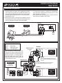
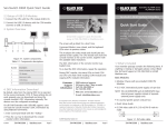
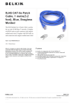
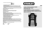
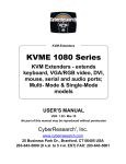
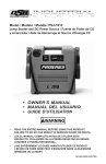
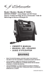
Model: MV-VS2
Installation and User Manual
The MV-VS2 is a mechanical video and audio switching device used to increase the number of inputs to the Mobile Video System
providing greater system flexibility and ease of use. Follow the enclosed diagrams to make proper connections.
Installation
The MV-VS2 has 3-way mounting capability. It can be mounted
under the dash or under a ledge, on the floor or on top of a ledge
and it can also be panel mounted in a cabinet, console or wall.
Installation Notes:
1. Choose a mounting location that provides easy access by
the end user.
2. Choose a solid mounting surface that will withstand the
pulling and pushing force when the end user is plugging in
and disconnecting devices.
3. If panel mounting, follow the recommendations in point #2.
The mounting surface must be able to withstand the pulling
and pushing force.
Surface Mounting:
Panel Mounting:
Use the “L” brackets provided to secure the MV-VS2 into place.
The brackets can be placed at the top of the MV-VS2 cabinet for
under dash or under ledge mounting or at the bottom of the cabinet for floor or surface mounting. DO NOT mount the MV-VS2
on uneven surfaces which will cause the brackets or chassis to
bend or flex excessively.
Remove the “L” brackets from the MV-VS2 housing and slip on the
panel mount adapter. Use the screws you removed from the “L”
brackets to secure the panel mount adapter to the MV-VS2 chassis.
You must cut a hole in the mounting surface approximately 5” x
1-3/4” in size.
Under Dash Mounting
Hole Opening
13/4"
PUT
IN
AV 2
AV
UT
3 INP
5"
PUT
IN
AV 1
A/
urce
3 So 2
MV-VS
lector
V Se
h
Switc
ECT
UT
INP
SEL
UT
P
1 IN
AV
Panel Mounting
Surface Mounting
PUT
IN
AV 2
AV
PUT
IN
AV 3
UT
1 INP
itch
r Sw
PUT
IN
AV 2
PUT
IN
AV 3
/V
rce A
3 Sou 2
S
MV-V
to
Selec
ECT
UT
INP
PUT
IN
AV 1
A/
urce
3 So 2
MV-VS
V Se
h
Switc
lector
SEL
UT
ECT
P
1 IN
AV
SEL
PUT
IN
PUT
1 IN
AV
© 2006 Copyright Magnadyne Corporation
MV-VS2-INS Rev. A 2-15-06
Installation and User Manual
Model: MV-VS2
Connection and Operation
1. A 6 foot long RCA male patch cord is provided with the MVVS2 to make the connection from the MV-VS2 output on the
rear panel to the Mobile Video System Screen. Some installations may require a longer cable which can be purchased at a
local electronics store.
2. Both “Rear Aux Inputs” of the MV-VS2 are typically reserved
for permanent items that will not be removed from the vehicle
such as a video game controller, VCD or second DVD.
3. The front panel connection is typically for non-permanent
items that will be removed from the vehicle such as a video
game controller or camcorder.
4. The 3 position switch on the front panel is used to select the
signal source to the Mobile Video system.
Front Panel
AV 2 INPUT
VIDEO GAME
3 Source A/V Selector Switch
MV-VS2
CAMCORDER
or
Not Supplied
AV 1 INPUT
AV 3 INPUT
Not Supplied
AV 1 INPUT
INPUT SELECT
Signal
Source
Switch
Industry Standard Color Code:
Yellow . . . Video Signal
Red = . . . Right Audio Signal
White = . . Left Audio Signal
Auxiliary 2
RCA Male Patch Cord
Not Supplied
LINE
OUT
All the connectors on the MV-VS2 are female
RCA type with industry standard color code
indication. Any device to be connected to the
MV-VS2 will require a 3 conductor Male-toMale RCA jumper cable that will either be
supplied with the device or can be purchased
at a local electronics store.
R
AUDIO
L
VIDEO
Not Supplied
AUDIO OUT
Connect Red White Male RCA Connectors from
patch cord connected to MV-VS2 Rear Aux Input
connectors
MV VS2 Rear Panel
AV 2 INPUT
Supplied (MV-VS2)
POWER SUPPLY
V
Supplied with
Some MV Systems
Permanent Item:
DVD,
Video Game
R
AV OUTPUT
L
V
R
L
VIDEO OUT
Connect Yellow Male RCA Connector from patch cord
connected to MV-VS2 Rear Aux Input connectors
AV 3 INPUT
Auxiliary 3
RCA Male Patch Cord
Supplied
LINE
OUT
R
AUDIO
L
Permanent Item:
DVD,
Video Game
VIDEO
Not Supplied