1
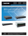
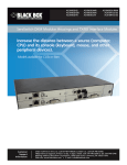
ServSwitch DKM Quick Start Guide
ACX1MT, ACX1MR Series
ACXMODH Series
2.3 Setup of USB 2.0 Modules
1. Connect the CPU with the CPU module (USB 2.0).
2. Connect the USB 2.0 devices with the CON module
(connect to USB 2.0 devices).
3. System Overview
ServSwitch DKM Modular Extenders
Black Box Tech
Support: FREE! Live.
24/7. Tech support
the way it should be.
BLACK BOX
®
Great tech support is just 30 seconds
away at 724-746-5500 or blackbox.com.
Quick Start Guide
BLACK B
Increase the distance between a source
(computer, CPU) and its console (keyboard,
monitor, and mouse) and other peripheral
devices.
The screen will go black for a short time.
1
2
3
Command Mode is now closed, and the keyboard
LEDs return to previous status.
4
This re-adjusts the video mode and should give you
optimal screen quality. The CPU should now show the
console monitor as the current screen, together with
the available video resolutions.
5
Figure 3-1. System components.
Table 2-1. Components descriptions.
Number
Description
1
Source (computer, CPU)
2
CPU Module
3
Interconnect cable
4
CON Module
5
Console (monitor, keyboard, mouse)
The DDC information of the console monitor was
loaded once.
To re-load the DDC information, repeat the operation.
During DDC transfer, the status LEDs on both CON
and CPU units flash while reading (CON module) and
copying (CPU module) information.
Customer
Support
Information
4. DDC Information Download
By default, data from the internal DDC list is reported
to the source (computer, CPU). If these settings do not
work properly, you can download and store the
console monitor’s DDC information internally. The
devices must be configured accordingly.
On all KVM Extenders with USB-HID support, users
can load the console monitor’s DDC information by
using keyboard commands.
1. Enter Command Mode with the “hotkey.”
2. Press the <a> key to download the console
monitor’s DDC information.
ACX1MT
724-746-5500 | blackbox.com
FREE technical support
24 hours a day, 7 days a week:
Call 724-746-5500 or
fax 724-746-0746
Web site: www.blackbox.com
E-mail: [email protected]
© Copyright 2011. Black Box Corporation. All rights reserved.
Black Box and the Double Diamond logo are registered trademarks,
and ServSwitch is a trademark, of BB Technologies, Inc. TOSLINK is a
registered trademark of Kabushiki Toshiba dba Toshiba Corporation.
Any other trademarks mentioned in this manual are acknowledged to
be the property of the trademark owners.
724-746-5500 | blackbox.com
Your extender package contains the following items. If
anything is missing or damaged, please contact Black
Box Technical Support at 724-746-5500 or info@
blackbox.com.
Basic Modules:
• Modular Chassis with pre-installed CON/CPU
Modules
• (1) 5-VDC international power supply unit per box
NOTE: The ACXMODH6R and ACXMODH21R have
internal power supplies instead of separate
external power supply units.
• (1) country-specific power cord per box
• Quick Setup Guide
• (1) DVI video cable (6 ft. [1.8 m] DVI-D male-tomale)
Figure 1-1. DVI video cable.
ACX1MT Quick Start Guide, rev. 1
Page 5
1. What’s Included
Page 6
724-746-5500 | blackbox.com
ServSwitch DKM Quick Start Guide
ServSwitch DKM Quick Start Guide
ServSwitch DKM Quick Start Guide
• (1) USB cable (6-ft. [1.8 m], Type A to Type B)
The upgrade module USB-HID also includes:
6. Connect the CPU Module to the interconnect
cable(s).
• USB cable (6-ft. [1.8 m], USB Type A to Type B)
7. Connect the 5-VDC power supply to the CPU
Module.
Figure 1-2. USB cable.
The basic module VGA (replaces DVI-D cable) also
includes:
• VGA cable (6-ft. [1.8 m], VGA male to DVI-I male)
8. Power up the system.
Figure 1-8. USB cable.
NOTE: To power up the system, the following
sequence is recommended: Monitor – CON Module –
CPU Module – source.
The USB 2.0 module also includes:
• USB cable (6-ft. [1.8 m], USB Type A to Type B)
NOTE: The basic module with VGA/DVI-I input is
connected as mentioned above. For a complete
and detailed description of the setup and
configuration of the VGA option, see the
Media/DVI Converter (ACS411A-R2) manual.
Figure 1-9. USB cable.
Figure 1-3. VGA cable.
2. System Setup
• Infrared remote control
The upgrade module Analog Audio/Serial also
includes:
• Serial cable (6-ft. [1.8 m], RS-232 male connector)
NOTE: If you are a first-time user, we recommend that
you set up the system with the CPU Module
and the CON Module in the same room as a
test setup. This will enable you to identify and
solve any cabling problems, and experiment
with your system more conveniently.
NOTE: Verify that interconnect cables, interfaces, and
handling of the devices comply with the
requirements (see the user’s manual).
Figure 1-4. Serial cable.
• Stereo jack cable (5.2-ft. [1.6-m], 3.5-mm male
connector)
2.1 Basic Module Setup
Figure 1-5. Stereo jack cable.
The upgrade module Digital Audio also includes:
• RCA cable (8.2-ft. [2.5-m], Cinch male connector)
Figure 1-6. RCA cable.
• TOSLINK cable (6-ft. [1.8 m], F05 male connector)
®
ACX1MT
724-746-5500 | blackbox.com
Upgrade Module Analog Audio/Serial:
1. Connect the audio source with the CPU Module (for
example, CPU audio output with audio input, CPU
audio input with audio output).
2. Connect the audio output at the CON Module with
headphones or suitable speakers.
3. Connect the audio input at the CON Module with a
suitable microphone.
CON Module Installation
Upgrade Module Digital Audio:
2. Connect your monitor(s), keyboard, and mouse to
the CON Module.
1. Connect the digital audio source with the suitable
audio input of the CPU module.
3. Connect the CON Module with the interconnect
cable(s).
2. Connect the audio output of the CON Module with
suitable speakers or audio amplifiers.
4. Connect the 5-VDC power supply to the CON
Module.
NOTE: If several active sources are connected, MiniXLR input takes priority. The audio signal is
available at all outputs.
5. Connect the source (computer, CPU) with the
supplied cables to the CPU Module. Make sure the
cables are not strained.
Page 2
You can hot-plug the modules.
1. Switch off all devices.
CPU Module Installation
Figure 1-7. TOSLINK cable.
2.2 Setup of Upgrade Modules
ACX1MT
724-746-5500 | blackbox.com
Page 3
Upgrade Module USB-HID:
1. Connect the CPU with the CPU Module (USB-HID 2).
2. Connect the USB-HID devices with the CON Module
(Connect to USB-HID device 2).
ACX1MT
724-746-5500 | blackbox.com
Page 4