1
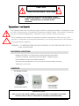
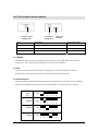
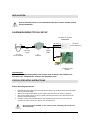
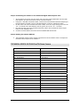
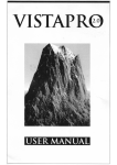
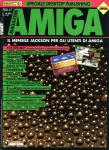
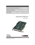
AUTO PAN TILT COLOR DOME CAMERA FOR USE WITH VISTAPRO4 DIGITAL MONITORING SYSTEM DCP1000 DYNACOLOR CAUTION RISK OF ELECTRIC SHOCK. DO NOT OPEN. ! CAUTION: TO REDUCE THE RISK OF ELECTRIC SHOCK, DO NOT REMOVE COVER (OR BACK). NO USER-SERVICEABLE PARTS INSIDE. REFER SERVICING TO QUALIFIED SERVICE PERSONNEL. Explanation of two Symbols The lightning flash with arrowhead symbol, within an equilateral triangle, is intended to alert the user to the presence of uninsulated "dangerous voltage" within the product's enclosure may be of sufficient magnitude to constitute a risk of electric shock to persons. ! The exclamation point within an equilateral triangle is intended to alert the user to the presence of important operating and maintenance-(servicing) instructions in the literature accompanying the appliance. WARNING – TO PREVENT FIRE OR SHOCK HAZARD, DO NOT EXPOSE THE UNIT TO RAIN OR MOISTURE. FEATURES & FUNCTIONS Reliable, high quality 1/4" CCD Camera providing optimum image clarity Connects to computer via Interface box and RS232C – RS485 converter* Remote PAN/TILT control with VistaPro4 software Slow speed Pan/Tilt operation (15° per second) at 355° pan and 80° tilt range 3.6mm lens, 1Lux (F 2.0) CONTENTS This Package Contains: DCP1000 Color Auto Pan Tilt Color Dome Camera Pan Tilt Controller Interface Module 65 ft DIN extension and 7 ft RS485 connection cables *IMPORTANT NOTE: THIS AUTO PAN TILT DOME CAMERA CANNOT FUNCTION ON VISTAPRO4 SOFTWARE WITHOUT THE ACC-RS232 CONNECTOR ACCESSORY (SOLD SEPARATELY) 1 Pan Tilt Controller Interface Module ① ② ②DVR INPUT CONNECTOR ①CAMERA INPUT CONNECTOR ③ ③6PIN DIP SWITCH Port Description Connection Type To Camera RS-485 data input/ video input 6 Pin DIN jack To DVR Serial data output / video output 6 Pin DIN jack SW 1 -6 Camera ID selection 6 Pin DIP switch TO CAMERA - transmits the Pan/Tilt control signals from the VistaPro 4 to the DCP1000 Dome Camera - receives the video signal from the DCP1000 Camera to the VistaPro 4. TO DVR - receives the RS-485 signal from the PC’s Comm port (via the ACC-RS232 connector) - transmits the video signal that comes from Pan/Tilt Dome Camera to DVR. 6 PIN DIP SWITCH - sets the Channel ID of Pan/Tilt Dome Camera to correspond to the channel on the VistaPro4. Refer to the diagram below for how to set the Dip Switch to correspond with a camera. CAM ID: 1 ON CAM ID: 2 ON CAM ID: 3 CAM ID: 4 1 2 3 4 5 6 1 2 3 4 5 6 1 2 3 4 5 6 1 2 3 4 5 6 ON ON 2 INSTALLATION Ensure electrical power is not connected to the dome camera and PC system during installation. DIAGRAM SHOWING TYPICAL SET-UP RS-232C to RS-485 CONVERTER RS-485(+) RS-485(-) 65ft 6Pin Din Cable Pan/Tilt Dome Camera RS-232C (to PC COM Port) 7ft RS485 Cable PT Interface DC12V VIDEO (VistaPro 4 Main Board) Important Note: For the P/T/Z Camera Model setting in the Camera menu of Setup in the VistaPro4, the DCP1000 is the “DYNACOLOR” camera in the drop down menu. STEP BY STEP SETUP INSTRUCTIONS Step 1: Mounting the Camera Separate the back-plate from the base of the camera by gently twisting the base while securing the back plate. Attach the camera back plate on the ceiling using the Ø3 X 20 screws (supplied) Secure the camera to the ceiling by gently twisting the base of the camera onto the ceiling mounted back plate Connect the 65’ Camera DIN cable to the female DIN input found on the Camera. Connect the other end of the cable to the Interface box. Do not hold clear bubble or the swivel when attaching the camera to the back plate. 3 Step 2: Connecting the Camera to the VistaPro4 Digital Video Capture Card At the location of the PC, plug the other end of the 65’ Camera DIN cable into the DIN port labeled “To Camera” found on the PT interface module. Using the 7’ RS-485 Connection Cable, connect the end terminated with the DIN plug to the port labeled “To DVR” (next to the DIP switches) on the PT Interface module. On the other end of the RS-485 Connection Cable, screw the single orange wire into the “TX +” terminal of the ACC-RS232, and the green wire to the “TX –” terminal. Plug the RCA jack (from the RS-485 Connection cable” into the desired Camera Input found on the VistaPro4 card. Connect the ACC-RS232 connector into an available DB9 Comm Port. Step 3: Setting the Camera Address The Dip Switch setting of the camera connected to the PT Interface must correspond to the RCA Camera Input of the VistaPro 4 TECHNICAL SPECS: DCP1000 Pan/Tilt Dome Camera Image sensor 1/4" Color CCD Active pixels 512(H) X 492(V) Image sensor area 4.8(H) X 3.7(V) mm Resolution > 330 TV lines Min. illumination 1 Lux (F2.0) Video output 1.0V p-p (75 ohms) Electronic iris 1/60 ~ 1/100,000 sec Lens 3.6mm Synchronization Internal Signal format 525 lines, 2:1 interlace System connection 6 Pin Mini DIN jack Power source DC12V (from interface or controller) Power consumption MAX. 2.4W Operating temperature -10°C ~ +50°C Dimension 126 X 107 mm Weight 1Kg Pan/Tilt speed 15° per second Pan travel 355° Tilt travel 80° 4