1
VIST
RS
USER MANUAL
USER MANUAL
VIRTUAL REALITY LABORATORIES, INC.
PROGRAM LICENSE AGREEMENT
The program Vistapro is copyrighted by Hypercube Engineering, and
the related user manual is copyrighted by Virtual Reality Laboratories,
Inc. You may not copy, modify, distribute, transfer or transmit this
program or the related manual except as is expressly provided in this
agreement. You have the non-exclusive right to use this program on all
of the Commodore Amiga computers within a single household. You
may make as many backup copies of this program as you like, as long as
you guarantee that they are not in use in more than one household at a
time. Businesses should contact VRLI for site licensing. This program is
sold as entertainment, without warranty as to its suitability to be used for
any other purpose. Virtual Reality Laboratories, Inc. warrants to the
original licensee that the diskette(s) on which Vistapro is recorded shall
be free from defects in material and workmanship for a period of sixty
(60) days from the date of purchase. If such a covered defect occurs
during the first sixty days, return the disk to VRLI, 2341 Ganador Court,
San Luis Obispo, CA 93401, within five (5) days after the sixty day limit,
and wewillreplaceitfree ofcharge. Replacement after the sixty day limit
will be done at the rate of $10.00 per disk to cover costs of media, shipping
and handling. Virtual Reality Laboratories, Inc.' sliabilityis limited to the
replacement of defective media. This license agreement shall be governed by the laws of the United States of America and the State of
California. Commodore Amiga, Inc. makes no warranties either expressed or implied, regarding the enclosed computer software package,
its merchantability, or its fitness for any particular purpose. Amiga,
Amigados, Workbench, Kickstart, and Intuition are trademarks of Commodore Amiga, Inc. Turbo Silver is a trademark of Impulse, Inc.
iii
Manual layout, indexing and production & Packaging design by
LaserDesign
iv
P.O. Box 368, San Luis Obispo, CA 93406
CONTENTS
INTRODUCTION TO VISTAPRO ........................................................ 1-1
Notes on Vistapro .................................................................................... 1-2
Vistapro String Gadgets .................................................................... 1-2
Vistapro on Accelerated Amigas ...................................................... 1-2
Vistapro Landscapes ......................................................................... 1-2
Vistapro Stack Requirements ........................................................... 1-3
Loading Vistapro from the CU or a Shell ....................................... 1-3
Limits of Vistapro's World ............................................................... 1-4
What is Vistapro? .................................................................................... 1-4
How Vistapro Works .............................................................................. 1-4
Some Uses for Vistapro .......................................................................... 1-5
Speeding Up Vistapro ............................................................................. 1-6
Making the Most of Vistapro ................................................................. 1-7
Lighting .............................................................................................. 1-7
Snow and tree line setting considerations ....................................... 1-7
Changing colors ................................................................................. 1-8
Foreground "fat polys" or "jaggies" ................................................ 1-8
A note about aesthetics ..................................................................... 1-9
Exploration with Vistapro ................................................................ 1-9
Your own data ................................................................................. 1-10
VISTAPRO USERMANUAL ..................................................................... 2-1
Getting Started ......................................................................................... 2-1
Floppy System ......................................................................................... 2-1
Installation .......................................................................................... 2-1
Making Working Copies ................................................................... 2-1
One Drive Systems: ........................................................................... 2-1
Multiple Drive System: ..................................................................... 2-2
Renaming Your Working Copy ....................................................... 2-2
Hard Disk ................................................................................................. 2-3
General Information About Vistapro ................................................... 2-3
The Vistapro Disks ............................................................................ 2-3
VISTAPRO MENUS .................................................................................... 3-1
Project Menu ............................................................................................ 3-1
Landscape Size ................................................................................... 3-2
Small ............................................................................................ 3-2
Large ............................................................................................ 3-2
Huge ............................................................................................ 3-2
Auto ............................................................................................. 3-3
v
Load Image ........................................................................................ 3-3
IFF ................................................................................................ 3-4
IFF 24 ........................................................................................... 3-4
Save Image ......................................................................................... 3-4
IFF ................................................................................................ 3-4
IFF 24 ........................................................................................... 3-4
RGB ............................................................................................. 3-5
Load Landscape ................................................................................. 3-5
Vistapro DEM ............................................................................. 3-6
DEM Region ............................................................................... 3-7
ColorMap .................................................................................... 3-8
Binary .......................................................................................... 3-8
Save Landscape ................................................................................. 3-8
Vistapro DEM ............................................................................. 3-9
Turbo Silver ................................................................................ 3-9
ColorMap .................................................................................. 3-10
Extended DEM ......................................................................... 3-10
Print .................................................................................................. 3-10
About ................................................................................................ 3-11
Vistapro ..................................................................................... 3-11
Landscape ................................................................................. 3-11
Quit ................................................................................................... 3-11
Script Menu ............................................................................................ 3-12
Generate ........................................................................................... 3-13
Create ................................................................................................ 3-13
Open ............................................................................'..................... 3-13
Add ................................................................................................... 3-14
Preview ............................................................................................. 3-14
Execute ............................................................................................. 3-14
Anim Mode ...................................................................................... 3-14
IFF .............................................................................................. 3-14
IFF24 .......................................................................................... 3-15
RGB ............................................................................................ 3-15
VANIM ..................................................................................... 3-15
Display Menu ......................................................................................... 3-17
Image Size ........................................................................................ 3-17
Low Res ............................................................................................ 3-18
HalfBrite ........................................................................................... 3-18
Hi Res ............................................................................................... 3-18
HAM ................................................................................................. 3-19
DCTV ................................................................................................ 3-19
HAM-E ............................................................................................. 3-19
Interlace ............................................................................................ 3-20
vi
Overscan ........................................................................................... 3-20
Off .............................................................................................. 3-20
704 .............................................................................................. 3-20
736 .............................................................................................. 3-20
768 .............................................................................................. 3-20
Firecracker ........................................................................................ 3-21
Off .............................................................................................. 3-21
1 Monitor ................................................................................... 3-21
2 Monitors ................................................................................. 3-21
Background ...................................................................................... 3-22
Foreground ...................................................................................... 3-22
Property Menu ....................................................................................... 3-22
Col->lff ............................................................................................ 3-23
Iff-> Col ........................................................................................... 3-24
Alt-> Iff ........................................................................................... 3-24
lff -> Alt ........................................................................................... 3-25
View-> Col ...................................................................................... 3-25
View-> Alt ...................................................................................... 3-26
View - > RGB ................................................................................... 3-26
CONTROL PANELS ................................................................................... 4-1
Target ........................................................................................................ 4-2
UPPER CONTROL PANEL ...................................................................... 4-2
Camera ...................................................................................................... 4-3
Locking Functions ................................................................................... 4-3
p ................................................................................................................. 4-4
dR ............................................................................................................... 4-5
dX ............................................................................................................... 4-5
dY ............................................................................................................... 4-5
dZ ............................................................................................................... 4-5
Bank ........................................................................................................... 4-6
Head ................................................................................................. ;........ 4-6
Pitch ........................................................................................................... 4-6
Range ......................................................................................................... 4-6
SeaLvl ........................................................................................................ 4-8
MIDDLE CONTROL PANEL ................................................................. 4-8
TreeLn ....................................................................................................... 4-9
Oak .................................................................................................... 4-10
Pine ................................................................................................... 4-10
Palm .................................................................................................. 4-10
Cactus ............................................................................................... 4-10
TreSiz ................................................................................................ 4-11
TreDns .............................................................................................. 4-11
vii
SnowLn ................................................................................................... 4-11
HazeDn ................................................................................................... 4-12
Lake ......................................................................................................... 4-12
River ........................................................................................................ 4-13
Smooth .................................................................................................... 4-14
CMap ....................................................................................................... 4-14
Stars ......................................................................................................... 4-14
Sky ........................................................................................................... 4-15
Horiz ....................................................................................................... 4-15
LockP ....................................................................................................... 4-16
Enlarg ...................................................................................................... 4-16
VScale ...................................................................................................... 4-17
LOWER CONTROL PANELS ............................................................... 4-18
Main ........................................................................................................ 4-18
Lens ......................................................................................................... 4-18
Frac .......................................................................................................... 4-18
Light ........................................................................................................ 4-18
MAIN LOWER CONTROL PANEL .................................................... 4-19
Poly .......................................................................................................... 4-19
Dither ...................................................................................................... 4-20
Textur ...................................................................................................... 4-20
OLMH .................................................................................... 4-20
PixDth ..................................................................................................... 4-21
Bound ...................................................................................................... 4-21
BFCull ...................................................................................................... 4-22
Blend ....................................................................................................... 4-22
Gshade .................................................................................................... 4-22
LENS LOWER CONTROL PANEL ...................................................... 4-23
Wide ........................................................................................................ 4-23
Zoom ....................................................................................................... 4-23
Zoom Value ............................................................................................ 4-24
FRACTAL LOWER CONTROL PANEL .............................................4-25
Random ................................................................................................... 4-25
Island ....................................................................................................... 4-26
FrDim ...................................................................................................... 4-26
Frctlz ........................................................................................................ 4-26
Stretch ..................................................................................................... 4-27
Fractal Landscape Number .................................................................. 4-27
Fractal Divisor ........................................................................................ 4-27
viii
LIGHT LOWER CONTROL PANEL .................................................. 4-28
NSEW ...................................................................................................... 4-29
Custom .................................................................................................... 4-29
Exager ...................................................................................................... 4-29
Azimth .................................................................................................... 4-30
Declin ...................................................................................................... 4-30
Rough ...................................................................................................... 4-30
Shadow ................................................................................................... 4-30
BOTIOM CONTROL PANEL .............................................................. 4-31
Render ..................................................................................................... 4-31
Redraw .................................................................................................... 4-31
View ........................................................................................................ 4-31
Abort ....................................................................................................... 4-32
THE VISTA STATUS WINDOW ............................................................ 5-1
X, Y, Z: ...................................................................................................... 5-1
Generate: ................................................................................................... 5-2
Color .......................................................................................................... 5-2
Cliffs .......................................................................................................... 5-2
Shade ......................................................................................................... 5-2
Tree ............................................................................................................ 5-2
Sky ............................................................................................................. 5-2
Horizon ..................................................................................................... 5-3
Render: ...................................................................................................... 5-3
COLOR CONTROL PANEL .................................................................... 6-1
Colors ........................................................................................................ 6-1
OK .............................................................................................................. 6-3
Spread ....................................................................................................... 6-3
Quit ............................................................................................................ 6-3
Copy .......................................................................................................... 6-3
Swap .......................................................................................................... 6-4
Sound ........................................................................................................ 6-4
COLORS ........................................................................................................ 6-S
Sky ............................................................................................................. 6-5
Cliff 1-4 ...................................................................................................... 6-5
Snow 1-4 ................................................................................................... 6-5
Bare 1-4 ...................................................................................................... 6-5
Tree 1-4 ...................................................................................................... 6-5
Beach ......................................................................................................... 6-6
Horizon ..................................................................................................... 6-6
Water 1-5 ................................................................................................... 6-6
SkyHaze .................................................................................................... 6-6
Haze ........................................................................................................... 6-6
-Tree 1-4 .................................................................................................. 6-6
ix
Bark 1-4 ..................................................................................................... 6-7
House 1-4 .................................................................................................. 6-7
-House 1-4 .............................................................................................. 6-7
Exposure ................................................................................................... 6-7
Contrast ..................................................................................................... 6-7
VIEWER .......................................................................................................... 7-1
APPENDIX A ................................................................................................ 8-1
What are Fractals and Fractal Geometry? ............................................ 8-1
APPENDIX B ............................................................................................... 8-4
The Landscapes ....................................................................................... 8-4
ElCap.dem: ............................................................................................... 8-4
HalfDome.dem: ....................................................................................... 8-4
CraterLake.dem: ...................................................................................... 8-4
MSHB.dem: and MSHA.dem: ............................................................... 8-5
Mons.dem: ................................................................................................ 8-5
Julia.dem: and Mandelbrot.dem: .......................................................... 8-6
Arrowhead.dem: ..................................................................................... 8-6
Vantage.dem: ........................................................................................... 8-6
SanLuisObispo.dem: ............................................................................... 8-6
SanGorgonio.dem: ................................................................................... 8-6
BigSur.dem: .............................................................................................. 8-7
MorroBay.dem: ........................................................................................ 8-7
MtBaldy.dem: ........................................................................................... 8-7
MtAdams.dem: ........................................................................................ 8-7
WoodSh.dem: ........................................................................................... 8-8
Grand Canyon.dem: ................................................................................ 8-8
Sundial.dem: ............................................................................................ 8-8
APPEND IX C ............................................................................................... 8-9
x
Glossary of Terms ................................................................................... 8-9
AI ........................................................................................................ 8-9
Aliasing Artifacts ............................................................................... 8-9
Caldera ............................................................................................... 8-9
DEM .................................................................................................... 8-9
Digi Paint ............................................................................................ 8-9
Digital Elevation Model .................................................................... 8-9
Dithering .......................................................................................... 8-10
Fat Polys ........................................................................................... 8-10
Fractal ............................................................................................... 8-10
Fractal Pro ........................................................................................ 8-10
HAM ................................................................................................. 8-10
Haze .................................................................................................. 8-10
IFF ..................................................................................................... 8-10
Jaggies ............................................................................................... 8-11
Olympus Mons ................................................................................ 8-11
Polygons ........................................................................................... 8-11
Ray Tracing ...................................................................................... 8-11
Topography ..................................................................................... 8-11
Topology .......................................................................................... 8-11
VISTAPRO TUTORlALS ........................................................................... 9-1
TUTORIAL 1-THE BASICS .................................................................... 9-2
Running Vista pro .................................................................................... 9-2
A Quick Introduction .............................................................................. 9-2
Loading a DEM Landscape .................................................................... 9-2
Setting Camera and Target Locations .................................................. 9-4
Viewing your Camera Position ............................................................. 9-6
Adjusting the Camera Lens ................................................................... 9-7
Making a Smoother Image ..................................................................... 9-7
Blend ......................................................................................................... 9-7
Gouraud Shading .................................................................................... 9-8
Dither ........................................................................................................ 9-8
Experiment ............................................................................................... 9-8
TUTORIAL 2 ................................................................................................ 9-9
MAKING A PRETTIER PICTURE ......................................................... 9-9
Loading an IFF Image ............................................................................. 9-9
Adding Texture ..................................................................................... 9-10
Setting the Timber Line ........................................................................ 9-10
Drawing Trees ...................................................................................... 9-10
Setting Tree Density .............................................................................. 9-11
Setting Snow Level ................................................................................ 9-11
Adding a Lake ....................................................................................... 9-11
Adding a River ...................................................................................... 9-12
Changing the Haze Level ..................................................................... 9-12
Setting the Light Direction ................................................................... 9-12
Shadows and Exaggeration ................................................................. 9-13
Changing Colors .................................................................................... 9-13
Saving the Color Map ........................................................................... 9-14
Loading a Color Map ............................................................................ 9-14
Saving your Rendered Image .............................................................. 9-14
INDEX .......................................................................................................... 10-1
xi
INTRODUCTION TO VISTAPRO
Vistapro makes pictures of landscapes from two different types of data.
Pictures ofreallandscapes are made from U.S. Geological Survey Digital
Elevation Model data. The user can also explore billions of imaginary
fractal landscapes generated from data produced by Vistapro itself.
Starting with the control screen, you will notice a rectangular picture
bordered by blue on the left two-thirds of the screen. This contains a
topographical map of the landscape that you can explore. Vistapro' s
topographic map uses shades of green to represent the lowest altitudes,
browns to represent the middle altitudes, and gray-whites for the
highest altitudes. You can control Vistapro using the buttons on the right
side of the screen.
To get acquainted with Vistapro, move the red crosshair to the Camera
button and click the left mouse button. Note that the Camera button
appears indented, which means the crosshairwill now place the Camera
(the small black square on the map) when you click the left mouse button
over the topographic map. Note that the X, Y, Z coordinates within the
boxes next to the X, Y, and Zbuttons, change each time you click on a new
Camera location. The Z coordinate shows the altitude of your camera. It
is automatically set to 30 meters above the point that you clicked on.
When you have your camera placed where you want it, add several
hundred units to the Z altitude by clicking on the numerical value and
puttinginthenewnumber.Besuretopressreturnafterenteringthenumber,
and don't click on the Z button itself, since this locks the Z into its initial position.
The extra altitude will put the camera far enough above the surface to
reduce the size of polygons in the foreground. Next, click on the Target
button, then click on the topographic map to place the target. Now a
small+willappearonthemaptoidentifythetargetlocat ion.Themanual
contains information on how to use all the other controls, but for now,
please click on the CMap button. This will cause the other control screen
for Vistapro to appear. This screen is used for adjusting the colors,
contrast, and brightness used to paint the landscape. Since this is merely
atour,don'tchangeanyofthesettings.ClickonOKatth ebottomleftpart
of the screen to return to the primary control screen. Using the right
mouse button, go to the top left part of the primary control screen to view
your pull down menus. Don't select any right now. Again, the manual
1-1
describes their usage in detail. Click Render on the bottom control panel
and wait. Vistapro will render (draw and color) a rough (big polygon)
view of the target you have chosen. After it has rendered the picture, a
click on any part of the screen will return you to the primary control
screen. Notice that the default Poly value is 8. This is the roughest and
fastest view. It helps you quickly reset the camera view and lighting until
you think you have it thewayyou wantit. The lower Polyvalues increase
the rendering time as they yield a more detailed picture. Now that you
know your way around Vistapro, you may wish to take a few minutes
to follow the tutorials. We designed the tutorials to teach by doing. When
you have finished the tutorials, you will have an intuitive understanding
of Vistapro which will increase your ability to use the program. The
remainder of the manual is simply a reference text if you should want to
know more about a particular feature.
Notes on Vistapro
Vistapro String Gadgets
To change a numerical value on any Vistapro control panel, you must hit
the "return" key after typing the number. Simply entering the data will
not cause it to change from the beginning value unless "return" is
pressed.
Vistapro on Accelerated Amigas
The program selection "Vistapro" is for those who have standard Amiga
500' s, 1000' s or 2000' s without an accelerator board. We optimized the
program selection "Vistapro.881" for use with a 68020, or 68030 AND a
68881 or 68882 math co-processor or a 68040. Vistapro.881 will NOT run
without a math co-processor or on a 68000 based machine. Both programs are otherwise identical.
Vistapro Landscapes
All Vistapro Landscapes on the disk have the file protection mode set to
"read only". This assures that you will not accidently delete a landscape.
The "Protect" function on your Workbench will allow you to reset the
1-2
protection. You may set "Normal" protection by typing "Protect
<filename> rwed" where <filename> is the name of the file you want to
change. Do not type the "<" or ">" characters.
Vistapro Stack Requirements
Vistapro contains some recursive routines which may require large
amounts of stack space. IfVistapro is run via its icon from the Work.Bench,
you needn't worry about the stack- it has already been set up in the
Vistapro.info file. If Vistapro is run from a CU or Shell, you must ensure
that you run Vistapro with enough stack memory. From the CU or Shell
you can type "Stack" to see the current default stack setting. The usual
default value is 4000 bytes. (The Lake function is the only function
requiring much stack space. If you do not use the Lake function, you
don't need to increase the stack beyond the 4000 byte default.) Otherwise, if the current stack setting is fewer than 50000 bytes, we suggest
raising it. If it is very much larger, consider lowering it, especially if your
machine is short of memory (see "Loading Vistapro" below). To set the
default stack value to 50000 bytes, type "Stack 50000" from the CU or
Shell. Vistapro is now ready to use. If you are using Large or Huge mode,
50000 may not be enough stack space for all lakes. You may want to try
60000 bytes in Large mode and 120000 bytes in Huge mode.
Loading Vistapro from the CU or a Shell
Before starting Vistapro from a CU or Shell, be sure the default stack size
is set to at least 50000. You can start Vistapro from any CU or Shell by
typing "Vistapro" from the directory where Vistapro is located. You can
force Vistaproto load a particular landscape byincludingits device:path/
name on the command line. Some possible examples:
Vistapro ElCap.scape
Vistapro dfO:CraterLake.scape
Vistapro dhO:Vistapro /Landscapes /Mons.scape
You may, of course, simply type "Vistapro" and load a landscape via the
"Load Landscape" menu items.
1-3
Limits ofVistapro's World
Hypercube Engineering created a fast mixed integer and floating point
3-D engine for use in Vistapro. Vistapro displays landscapes properly,
when the Camera and Target are kept within -2000000000 and
+2000000000 (on all three axis). Placing the camera or target outside this
range or underground may result in distorted images, or no images at all.
What is Vistapro?
Vistapro is a 3 dimensional landscape simulation program. Using U.S.
Geological Survey (USGS) DEM (Digital Elevation Model) files, Vistapro
can accurately recreate real world landscapes in vivid detail. As a fractal
landscape generator, Vistapro can create landscapes from a random seed
number. Often these landscapes are more interesting than those found
in the real world. Vistapro supports over 4 billion different fractal
landscapes. Simply by changing a number, you can create whole new
worlds. Vistapro is also a tool. Besides simulating real and imaginary
landscapes, it allows extraction of a certain amount of data from the DEM
files. You can use the program output as an educational tool, as well as
a research tool for the study of topography. In addition, by simply
clicking on several buttons, you can create rivers and lakes in a landscape
where none existed previously. Vistapro converts DEM files to Turbo
Silver data which will enable you to import them into Turbo Silver or
similar ray tracing programs to add stunning realism to ray tracings. For
instance, you can add a house that you have worked on in a favorite
rendering package to areal world landscape. Imagine being able to place
an architectural creation on top of Mount St. Helens or on an island in the
middle of a fractal landscape!
How Vistapro Works
1-4
Vistapro uses a combination of artificial intelligence, chaotic math, and
a user definable set of values to simulate landscapes in their natural state.
At present, the USGS has converted about 40% of the United States and
its territories to DEM files which you can potentially use with Vistapro.
Vistapro is a single frame generator, meaning that it acts like a camera;
every time you point the camera and click, it will render a new view of
the landscape. You can view Landscapes from a practically infinite
combination of heights, angles, and distances. Using the combination of
user controllable values and Vistapro' s built-in routines, you are able to
make landscapes as realistic or as surreal as desired. It is easy to alter tree
and snow lines, haze, exposure, rivers, lakes, and light sources to
customize the appearance of the landscape. Vistapro uses data derived
from United States Geologic Survey Digital Elevation Mapping files for
generating its images. These files contain coordinate and elevation data
at 30 meter (roughly 100 ft.) increments. Each Small Vistapro DEM file
contains about 65,000 elevation points and generates 130,000 polygons.
A Large Vistapro DEM file contains about 256,000 data points and
generates 512,000 polygons, and a Huge Vistapro DEM file contains
about 1,000,000 data points and generates over 2,000,000 polygons.
Vistapro doesn't know anything about what covers the terrain. It doesn't
know where the trees, roads or buildings are. It does its best to color each
polygon (based upon a few numbers that you input) in a realistic way.
It still can't draw each rock and tree.
Some Uses for Vistapro
Vistapro is not only of interest to scientists and engineers. Artists, writers,
teachers, game designers, travelers, and people just looking for hours of
entertainment will appreciate Vistapro. Artists can design realistic scenery as backgrounds for their artwork. Writers can create worlds and see
them through their characters' eyes. Geography, geology, and meteorology teachers can use Vistapro to breathe life into their subjects. Game
designers can make realistic or surrealistic scenery for backgrounds in
their games. Travelers, hikers, and backpackers can preview their journeys. Vistapro can be pure entertainment. Explore fascinating terrains
that you might never have a chance to see, or visit distant planets that
man has not yet trod. Build new worlds that exist nowhere except in the
imagination, and then visit them as if they were really there. On the other
hand, there are many scientific and business applications for Vistapro.
Environmentalists, surveyors, geologists, architects and engineers will
all find Vistapro a useful adjunct to their work.
1-5
Speeding Up Vistapro
There are two ways to speed up Vistapro - strategy or brute strength.
After you have used the program for a while, you will learn to read" the
lower resolution settings in Vistapro to see if you are obtaining the
picture you want. When the scene is properly positioned and lighted,
and when you have set the tree line, snow line, and water levels where
you would like, then and only then, render the picture at the timeconsuming full resolution mode.
/1
The other alternative method of speeding up Vistapro's rendering
process is to add power to your machine. We programmed Vistapro to
use every available computing resource as efficiently as possible. The
time consuming rendering process is a function of the enormous amount
ofcomputation that Vistapro must do, not any lackofoptimizatio n of the
program itself. Vistapro will automatically look for and use whatever
processing resources you supply. When you add an accelerator board or
upgrade to a faster machine, Vistapro will take advantage of the additional processing power without any adjustment or request on your part.
Texturizing the landscape can take a significant amount of time, as can
the Tree functions. We suggest test rendering without those functions
active to prove" the scene, and then after you are satisfied with the
layout, add the Texturization and Trees.
/1
Realistic ray traced CAD objects, detailed 3-D animations, and realistic
landscapes are all a part of the emerging software categories called
virtual reality, artificial reality, or simulation. These categories all require
immense computational capacity, but as the cost of computing power
continues to plummet, these types of programs will become the standard. As a Vistapro user, you are pioneering virtual reality exploration
and it is admittedly a bit tedious on an unaccelerated machine. But,
looked at another way, it is amazing that this type of rendering can be
done at all, let alone on a personal computer. Until theadventofVistap ro,
landscape renderings of such realism were only available to users of
workstations and supercomputers for secret government projects.
1--6
Making the Most of Vista pro
Making a stunning landscape in Vistapro requires the combined eye of
a photographer and the artistic sense of a painter, but there are a few tips
which can help improve your first attempts:
Lighting
Experiment with the lighting. If the light is coming from behind the
camera, scenes may appear rather" flat." There won't be a strong feeling
of three dimensionality. You can create dramatic shadowing effects by
choosing the proper lighting direction and angle. With the power of
Vistapro, you can choose to light the scene in ways which could never
occur in the real world, or, if you are a purist, you can select the correct
solar position for that particular season and geographic location and
time of day. Our Distant Suns planetarium program (or most other
astronomy programs) can easily calculate such solar lighting conditions
in order to correctly set the light, target, and camera position to obtain
maximum realism in your rendering. If you just leave the lighting to
chance, you may find that shadows cover your scene, and it does not look
good. We find that setting the light source (the sun) at 45 to 90 degrees
to the left or right of the camera gives the best results. For example: if the
camera is facing due north, placing the sun at the southeast, east,
southwest or west, usually makes the best pictures. Placing the sun
directly behind the camera usually results in a lack of three dimensionality and contrast, although there are times when this is the desired effect.
Back-lit scenes (for example: camera facing north, sun shining from the
north) can also yield interesting images.
Snow and tree line setting considerations
If you know the normal range of snow line for the season that you are
viewing and at what altitude the tree line begins, you can use Vistapro
in a very realistic way. Tree line varies with latitude until, in arctic
regions, it reaches sea level. Snow levels vary with the weather and
altitude. A little research at the local library or even listening to the
weather on the evening news will allow you to increase the realism in
Vistapro landscape rendering. Of course you needn't follow the real
world as an example. You are free to set the tree and snow lines wherever
1-7
you want. You may want to see a landscape as it might have looked
during the last ice age, or maybe how it will look after severe global
warming from the greenhouse effect!
Changing colors
Use the Color Control Panel to change the colors, contrast, and exposure
used to render the landscape. Most landscapes shipped from us have
shades of green for lower elevations, brown for middle elevations, and
white for upper elevations. Try changing the Tree colors to pinks, and
whites. This makes them look like flowering fruit trees in the spring.
Change them to reds, browns and yellows for an autumn scene.
Foreground" fat polys" or "jaggies"
Since the accuracy of the data limits the detail that Vistapro can display,
some of the foreground features will contain fat polys" or "jaggies."
Vistapro builds all images with polygons - millions of polygons per
scene. The polygons are all about the same size but those near the camera
will appear very large on the screen, just as an object very near you will
look large, while when it is far away, it will look very small.
/1
There are several ways of reducing this effect. One of the simplest is to
raise the camera a few hundred meters above the ground. If you use the
mouse to position the camera it is automatically set 30 meters above the
landscape. Since the nearest polygon (the one right under the camera) is
only30metersawayitwilllookverylarge(ifitiswithinthefieldofview).
If you raise the camera 300 meters it will look about 10 times smaller.
A second method is to use the Texture function. This function breaks
nearby polygons up into several smaller pieces and renders each at a
slightly different shade - giving them a marbleized appearance.
Another way of hiding the foreground polys is to use the Tree function.
Trees are made of many small polygons and can obscure the large
polygons of the ground underneath them.
1-8
If you are looking at a rather small portion of the landscape you might
consider using the Enlarge function to blow that section oflandscape up
to twice its size.
/1
A third method of hiding fat polys" is to use Gouraud shading. This
blends the edges of the polygons with each other, eliminating the sharp
color change from one polygon to the next, and provides a beautiful
artistic interpretation of the scene. This shades even very large foreground polygons into oblivion. Texturizing and Gouraud shading can
be combined to generate even more interesting details.
Sometimes there is a small bump immediately in front of the camera that is
blocking a large part of the scene. Moving the Camera a few meters higher
maybe enough tomovethebumpoutofthefieldofview, ormovethe camera
far enough forward to get the bump behind it.
A note about aesthetics
/1
Remember, there is no more a right" way to use Vistapro than there is
a right" way to use a camera. A child using a camera or Vistapro may
derive a lot of knowledge and entertainment from a result which would
not please a more professional artist. Like the natural world it imitates,
Vistapro gives the artist an unlimited number of choices for portrayal.
What looks great to one person may not appeal to the next.
/1
Fractals imitate the way nature looks, but they are not the same. They
have no knowledge of geology, plate tectonics or erosion. So, whatever
pictures you produce with Vistapro will be interpretive because Vistapro
is producing an artificial reality to begin with. The philosophical and
aesthetic ramifications of virtual reality construction are immense.
Vistapro is an early forerunner of a medium of art and expression, as
powerful and unique as photography for creative work.
For many years after their introduction, photographs sparked lively
debate about whether they were art." Computer art and virtual reality
simulation seem destined to foment a similar debate in the future.
/1
Exploration with Vistapro
As a virtual reality simulator, Vistapro allows you to explore landscapes
you will probably never be able to explore first hand. We hope that most
of you will have the opportunity to visit a few of the national parks, but,
it is highly unlikely that any of us, except those who are now children,
will have the chance to tour the caldera of Mons Olympus on Mars. As
1-9
we are able to convert more of the data already available from planetary
probes and undersea explorers, Vistapro will allow you to explore
forbidding and alien landscapes decades, or even centuries, before the
first human explorer is able to take tourist snapshots. By giving its users
the ability to wander about distant landscapes, rendering true perspective pictures of their choice, Vistapro and later progeny will free humanity from its current boundaries long before such explorations are commercially feasible.
Your own data
Vistapro can be used to visualize any kind of surface which can be
represented as a two dimensional array of integers (up to 1024x1024).
Scanning tunneling electron microscope data is an example of such data
- think of it as a tiny, tiny landscape! You might even be able to convert
your backyard into Vistapro format!
1-10
VISTAPRO USERMANUAL
Getting Started
First make a backup of the Vistapro disk(s), following the instructions in
the AmigaDOS users documentation that came with your version of
AmigaDOS.
Floppy System
Installation
Before running Vistapro for the first time, you should make a working
copy of the Vistapro Program disk. If you lose the copy, then you will still
have the original.
Making Working Copies
These next few steps are here for the beginner, but you may use any of the
PublicDomainorCommercialDiskback-upprogramsyoufeelcomfortable
withtomakeaworkingcopyofVistapro.IFYOUHAVEANYPROBLEMS,
PLEASE READ THE AMIGADOSMANUAL 1HATCOMES WITH THE
MACHINE ON HOW TO DO BACK-UPS.
One Drive Systems:
1.
Insert Vistapro into the disk drive.
2. With the mouse, click on the Vistapro Icon with the left button once.
3. Now press and hold the right mouse button down and select
Duplicate from the project menu in the upper left hand comer of the
Workbench screen.
4.
AmigaDOS will prompt you with a Continue I Cancel requester.
5. With the left mouse button, press Continue.
2-1
6. Next AmigaDOS will prompt you to insert Vistapro. With the left
mouse button press Continue.
7. The disk drive light will come on, and the drive will spin for a while.
8. After a while, a requester will pop up and askforthe destination disk.
Insert the disk; this should be a blank.
9. Your Amiga will prompt you to insert the source disk. Then
AmigaDOS will ask you to insert the destination disk. AmigaDOS
may repeat this process several times, depending upon how much
memory you have in your Amiga. When you are finished, put the
original copy of Vistapro in a safe place.
Multiple Drive System:
1. Place Vistapro in one of the drives and the destination disk in one of
the other drives.
2. With the left mouse button, click on the Vistapro disk icon and hold
it down.
3. Next, drag the mouse, with the left button down, over the disk icon
where you want to place your copy of Vistapro. Once the Vistapro
icon is over the destination disk, release left mouse button.
4. If you have a Workbench or a hard disk, the copying will start. If not,
AmigaDOS will ask you to put the Workbench disk back in a drive
for a few seconds, so that the system can read the disk copy
command.
5. Follow the requester boxes, and in a minute or so you will have a
working copy of Vistapro.
6. When complete, put the original copy of Vistapro in a safe place.
Renaming Your Working Copy
The next step is to rename the working copy. If a good working copy has
been made, the disk should read 'copy of Vistapro'.
1. Click on' copy of Vistapro' disk icon once with the left mouse button.
2-2
2.
Now pre~s and hold the right mouse button down while selecting
Rename from the Project menu in the upper left hand comer of the
Workbench screen.
3. Next, a small window will open in the middle of the screen and the
name 'copy of Vistapro' should appear in it.
4. Press the DEL key until the' copy of is gone. Make sure to delete the
space before Vistapro.
5. Now press return. In a second, the Vistapro icon should read
'Vistapro', NOT' copy of Vistapro'.
Hard Disk
There is a hard disk installation script on the Vistapro disk To use it, you
must have booted from a complete Workbench, not from the Vistapro
disk Just double click on the Install icon and answer the questions as they
come up.
General Information About Vistapro
The Vistapro Disks
On the Vistapro disk you will find twocopiesofVistapro, a copy with the
name "Vistapro", and a copy with the name "Vistapro.881". There is an
install script called "Install HD" for hard disk installation. Also there is
a "Read Me" file for additional information that is not included in this
manual. On a second disk, named 'Landscapes', you will find several
Vistapro Landscapes for use with Vistapro. Vistapro's landscapes are
identical in format with Vistapro landscapes, and can be used by both
programs. The landscapes on the Vistapro disks are archived to take less
room on the disks, and must be unarchived by the Install program.
2-3
VISTAPRO MENUS
If you are not familiar with the way that you use menus on the Amiga,
simply click on the right mouse button when Vistapro is displaying the
control screen. This will show a title bar at the top of the screen. Keep
holding down the right mouse button and move the crosshair to one of
the two selections in the title bar. Continuing to hold down the right
mouse button, drag it down the menu. You will notice that it illuminates
various selections or causes another sub-menu to appear. Continue
holding down the button, until you illuminate your choice. Release the
button to select that choice.
There are three main menus in Vistapro: the Project Menu, which
controls loading, saving and printing, the Script Menu, which controls
script creation and execution, and the Display Menu, which controls the
different resolutions that are available with Vistapro.
Project Menu
Note- Many of the following menus involve the use of the Vistapro file
requester. The file requester contains a space to enter the name of the
drawer where you keep files of the given class, (ie. the Landscape drawer
for landscapes, or the Pie drawer for IFF images) a window containing
a partial listing of the contents of that drawer and a scroll bar to the right
of the window for scrolling the contents of the window, a space for the
name of the file you are dealing with, and a list of common device names
where you are likely to find the drawer. (ie. DFO:, OHO:, RAM:)
3-1
PROJECT MENU
Landscape Size
Small
The Small size landscape sets up a 258 x 258 topographic map region. It
works in most Amigas with at least 3 megabytes of available RAM, and
is used for loading single Vistapro Landscape files.
Large
The Large size landscape sets up a 514 x 514 topographic map region. It
works in most Arnigas with at least 4.5 megabytes of available RAM, and
is used for loading up to 4 small Vista pro Landscape files, or any single
Vista pro Landscape file up to514x514data points in size. Itisforusewith
Vistapro "X" series contiguous landscapes, to load large contiguous
regions. You may also load a small landscape and "enlarge" it to render
with more apparent detail. See "enlarge" function.
Huge
The Huge size landscape sets up a 1026 x1026 topographic map region.
It works in most Arnigas with at least 8 megabytes of available FAST
memory, and is used for loading up to 16 small Vistapro Landscapes
files, or any single Vistapro Landscape file up to 1026 x1026 data points
in size. The Huge size landscape is used with Vistapro "X" series
contiguous landscapes, loading large contiguous regions. You may also
load a small landscape and" enlarge" it twice to render in very fine detail.
See "enlarge" function.
Auto
Postpones setting up a topographic map region until it checks the header
of the Vista pro Landscape file next loaded with "Load Landscape". At
that time a topographic map region is set up to match the size of the file
to be loaded.
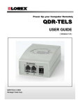
Load Image
The Load Image menu item allows you to Load and Display a previously
saved Vistapro Image File. The Drawer name will be the name of the
drawer in which you have saved lFF images, and the Device will be the
disk where you will find this drawer. On a single floppy system, the
drawer name will contain the name of the disk, followed by a colon ":",
followed by the name of the drawer where you will find the images, i.e.
MyDisk:Pics. On a hard disk, you might use something like
Work: Vistapro I Pies.
VISTAPRO FILE REQVESTOR
3-3
IFF
The Load, IFF submenu item loads standard Amiga IFF files, and IFF
HAM files, regardless of resolution.
IFF24
The Load, IFF 24 submenu item loads Amiga Commodore standard 24
bit IFF files, regardless of resolution. They must be no more than 768
pixels wide or 484 pixels tall. Smaller images will simply be loaded
towards the top left comer. After loading the 24 bit image data, Vistapro
will draw the image to the display screen at the current display settings.
Save Image
The Save Image menu item allows you to save an image that you have
rendered as an IFF file. The Drawer name will be the name of the drawer
in which you want to save IFF images, and the Device will be the disk
where you will find this drawer. On a single floppy system, the drawer
name will contain the name of the disk, followed by a colon":", followed
by the name of the drawerwhereyou will find theimages,ie. MyDisk:Pics.
On a hard disk you might use something like Work:Vistapro/Pics.
IFF
The Save, IFF submenu item saves in standard Amiga IFF format, using
the current settings of the display menu. You can load these images into
paint programs such as DPaint III for non-HAM renderings, and
DigiPaint 3 for HAM renderings. The picture that is saved is the one that
is currently on the "View" screen. This is usually the scene that has just
been rendered or redrawn.
IFF24
The Save, IFF 24 submenuitem saves in Amiga24 bit IFF format, with the
image width and height the same as the currently displayed image. For
example, if you are displaying in Lo-Res, no interlace, no overscan, this
will save a 320x320 IFF24 file.
3-4
RGB
The Save, RGB submenu item saves the Rendered image in the format
output by Sculpt-Animate 40. Vistapro produces only 746x484 pixel
files. They are given the base-name supplied by you with .ored",
.ogrn", .oblu" extensions used by the Mimetics framebuffer program,
version 1.01. For example, if you select PIC as the base picture name,
Vistapro will produce: Pic.ored Pic.ogrn Pic.oblu.
/1
11
/1
Vistapro has the ability to execute an AmigaDOS control file after
generating each frame of an animation. Vistapro passes the name of the
data file just produced (IFF, IFF24, or RGB formats) to the scripting
function. The control file can run whatever programs you want to
process the picture. For example, for the Mimetics framebuffer, you can
run the Mimetics Framebuffer program in command-line mode to
"encode" the picture and then delete the file .
.kFILE/a
c:fbuf -e <FILE>
c:Delete <FlLE>.ored
c:Delete <FlLE>.ogrn
c:Delete <FILE>.oblu
If you have a single-frame recorder, you could also send a command to
step the recorder, etc.
Load Landscape
The Load Landscape menu item allows you to load a Vistapro DEM
landscape file or Vistapro ColorMap header. The Drawer name will be
the name of the drawerin which you keep your landscapesorColorMaps,
and the Device will be the disk where you keep this drawer. On a single
floppy system, the drawer name will contain the name of the disk,
followed by the name of the drawer where you
followed by a colon
keep landscapes or ColorMaps.
/1
:",
3-5
Vistapro DEM
The Load Landscape, Vista pro DEM submenu item allows you to select
a Vistapro DEM Landscape file into Vistapro. This can be a landscape
that comes on the Vistapro disk, a landscape that you have previously
saved, or a landscape from a Vistapro expansion disk. Note that the
Landscapes that come with Vistapro and those that are on the Vistapro
expansion disks are write protected, to avoid the possibility that they will
accidentallyb eoverwrittenb yaSaveLands capecomman d.Tounprotec t
these images, (you probably will never need to do this) at the CU or
SHELL prompt, type "Protect <landscape>.scape rwed", where you
replace <landscape> with the name of the landscape you want to
unprotect.
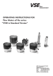
If you have set Size to "Large" or "Huge," a grid of landscape regions is
displayed in the topographic map region. When you have selected the
Load Landscape, Vistapro DEM submenu item, and have selected
"Large" or "Huge" previously, you will be asked to choose your
placement mode. Manual mode allows you to point to the quadrant of
the topographic map you want to load the landscape into, regardless of
whatever else may be there, and Auto looks at the coordinate information in the header of the landscape and tries to place it correctly in
relationship to other lan dscapes already loaded. If Vista pro cannot place
the landscape, it will warn you that the landscape is out of range. The
Auto feature works only with X series Vistapro DEMs.
3--6
LOAD LARGE PICTURE
LOAD HUGE PI CTURE
DEM Region
Vista pro will load the requested Landscape file into the lower left comer
of the topographic map region, and then search the current Landscape
directory for other landscapes that are located within the current topographic map region. The DEM Region function requires the "X" series
Vistapro Landscape files. Vistapro's Load-Region function will search
all files in a given directory for additional landscapes to load into the
current topographic region. It determines which landscapes to load by
examining the header of each landscape, the header has information
about the file's longitude and latitude. We highly recommend that you
installdifferentlandscapesets intodi.fferentdirectories.ThatwayVistapro
will have fewer files to examine when you load a region. There is also the
possibility that some data from other planets will overlap areas of the
earth, or that a DEM file you have modified (Vista pro saves the current
landscape's coordinates along with its other data) will load in on top of
the unmodified data. You wouldn't want Vistapro to have to search
through thousands of files to find the four that fit into the current area!
Also, the file requestor will take quite a while to fetch all the filenames
when there are thousands of files in a directory.
3-7
ColorMap
The Load Landscape, ColorMap submenu item allows you to load an
existing ColorMap onto a landscape that you have already loaded. This
does not affect the Landscape DEM data in memory, just the Color
Palette information. You can load a ColorMap from another Vistapro
DEM Landscape file, or from a Vistapro ColorMap file that you have
saved previously. See Color Control Panel for more information on
ColorMaps.
Binary
Binary loads the requested binary file as DEM data. Itis useful for porting
digital data that is not in DEM format into Vistapro or for those of you
trying to create your own landscapes. Vistapro' s binary format is very
simple. Each file consists of a number of signed 16 bit integers (Motorola
format on the Amiga - hi byte first, low byte second) in sequence. The
first integer in the file is loaded at the lower left hand corner (south-west
corner), the second to the right (east) of the first, etc. When the south-most
row is finished, the next row up (north) is loaded. Data continues until
all rows have been filled. A Small Vistapro landscape consists of 258x258
(rows x columns) integers (133,128 bytes). A Large Vistapro landscape
consists of 514x514 integers (528,392 bytes). A Huge Vistapro landscape
consists of 1026x1026 values (2,105,352 bytes). If your data is less than the
required size from left to right (east to west) you will have to either pad
to the required length or scale your data to fit. The file need not have
enough data to fill all rows; if the file is short the top part of the landscape
will simply be left with altitude 1.
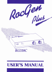
Save Landscape
The Save Landscape menu item allows you to save a Vistapro DEM
Landscape file, a Vistapro ColorMap header, or a Turbo Silver Object file.
The Drawernamewill bethename of the drawer in which you keep your
Landscapes,Color Maps,orTurboSilv erObjectfiles,and theDevicewill
be the disk where you keep this drawer. On a single floppy system, the
drawer name will contain the name of the disk, followed by a colon":",
followed by the name of the drawer where you keep Landscapes,
ColorMaps, or Turbo Silver Object files.
3--8
Vistapro DEM
The Save Landscape, Vista pro DEM submenu i tern allows you to save a
randomly generated fractal landscape as a Vistapro DEM Landscape
file. This file will not contain surface features such as lakes and rivers.
This will save the ColorMap now in effect, along with the landscape.
SAVE TURBO SILVER
Turbo Silver
The Save Landscape, Turbo Silver submenu item allows you to save the
currentJandsc apeasaTurboS ilverObjectfil e. Vistaprosave slandscapes
as Turbo Silver Objects at all levels. This is because Vistapro saves a
landscape as a series of Turbo Silver Objects, rather than a single one.
Vistapro saves landscapes at all polygon sizes. If Vistapro hasn' t yet
colored the landscape, it will inform you of this and give you the choice
of letting Vistapro color the landscape at the current setting or aborting
the save.
When you select the Save Landscape, Turbo Silver submenu item,
Vistapro will draw an eight by eight grid over the topographic portion
of the screen. You can then select a portion (or all) of the landscape by
clicking with the left mouse button on the upper left hand corner of the
area that you want saved as a Turbo Silver object. At this time you will
see a rubber band box appear, and you need to position the mouse to the
3-9
lower left hand comer of the area you want saved. This is the area within
the box. You then click again with the left mouse button.
Please note that these Turbo Silver objects are of extreme complexity, and
will require a good deal of memory to render when using Turbo Silver
or Imagine. A polygon sized2landscape will require at least 7 megabytes
of memory to render with Turbo Silver, and a complete polygon sized 1
landscape will require more than 30 megabytes. We suggest that you clip
only the regions that you actually need, in order to save memory, or
render at a larger polygon size (lower resolution).
ColorMap
The Save Landscape, ColorMap submenu item allows you to save the
current Color Palette settings as a Vistapro ColorMap. This does not save
the DEM Landscape data, and results in Vistapro saving a much smaller
file. You may want to keep several different ColorMaps around, so that
you can quickly load them into any landscape. See" Color Control Panel"
for more information on ColorMaps.
Extended DEM
Vistapro has an extended DEM format which allows you to save all the
current settings of the program along with the DEM data. This data
includes colors, shades, camera and target positions, script mode, haze
level-virtually every setting in the program. This is useful when
continuing an aborted animation. Extended DEM files range from
300KB to 400KB bytes each, for small landscapes, and up to 4 megabytes
for Huge landscapes.
Print
The Print menu item allows you to export Vistapro renderings directly
to your printer. This prints whatever is on your View Screen, so you can
use Load IFF to load an image into memory, and use Print to send it to
the printer if you want to do so.
3-10
About
Vistapro
The About, Vistaprosubmenu itemtellsyouabou ttheprogram Vistapro,
the authors, and the publishers.
Landscape
The About, Landscape submenu item tells you about the landscape,
including the file name, the landscape name, and any comments about
the landscape. This information comes from the header contained at the
beginning of Vista pro's Landscape files. If you generate a fractal landscape, and save it, the header will contain information about the fractal
setting used to generate the landscape, which you can use for your own
future reference.
Quit
The Quit menu item doses down Vistapro and returns you to the
Workbench.
SCRIPT MENU
3-11
Script Menu
The scripting controls allow creation of multiple unattended views of a
landscape. The scripts are lists of camera and target positions, and are
landscape independent. You can use the same script for several different
landscapes, or you can change the settings for the current landscape reexecuting the script. Script control allows changes to be made to the
landscape without having to rebuild the script every time. For instance,
if you want to change the light source direction, or if you want to see a
landscape from several views with and without water, all that you have
to do is make the appropriate changes and execute the proper script. (See
ReadMe.script).
Vistapro 2.0 also supports several additional script commands which
allow you to control most other function of the program from within a
script file. You can only generate these commands by editing the script
file with a text editor (Amiga's ED, TxEd, CED, etc ... ). The new commands have the following form:
CommandName: argument(s) comment
for example:
CameraX:
1234
VerticalScale: 1.2
Render:
Set Camera X position to 1234
Scale landscape to 1.2
Render landscape
The CommandName parameter can be either upper or lower case (or
mixed), and must have the trailing colon.
A missing numerical argument is treated as a 0.
Comments are, of course, optional.
For a list of commands, see the ReadMe.script file on your Vistapro
Diskl.
You can also access all of the Script functions with ARexx. For a complete
list of commands as well as instructions on how to use the ARexx
interface in Vistapro, see the file ReadMe.ARexx on your Vistapro Diskl.
3-12
Note: Many of the following menus involve the use of the Vistapro file
requester. The file requester contains a space to enter the name of the
drawer where you keep files of the given class, (ie. the Script drawer for
anim scripts, or the Anim drawer for IFF images) a window containing
a partial listing of the contents of that drawer and a scroll bar to the right
of the window for scrolling the contents of the window, a space for the
name of the file you are dealing with, and a list of common device names
where you are likely to find the drawer. (ie. DFO:, OHO:, RAM:)
Generate
This option allows you to make a quick linear path from the current
camera position to the current target position. This is most useful for
generating simple straight-line paths for animations. When you select
this option Vistapro asks for the name of the Script file to generate. It then
asks forthe number of frames. If the camera is 1000 meters from the target
and you select 100 frames, the camera will move 10 meters closer to the
target in each frame. The Bank, Heading, and Pitch will remain constant
(the camera will continue to point at the target). If you select the name of
an existing file Vistapro will ask you if you want to delete the file or abort
the operation. We recommend putting Script files in the Script
subdirectory, usually DHO:VlSTAPRO /SCRIPT.
Create
The Create menu item allows you to make a new script. When Create is
selected, Vistapro will display a file requester, from which you can select
the device where you wantto save the script, the drawer you want to put
thescriptin,andthenameof thescript.Ifyouattempttoc reateanexisting
file, Vistapro will overwrite that file. After the script name is entered,
Vistapro will create a blank script file and open it for use with the Add
option.
Open
Open will retrieve a previously created file for appending new frames.
When Open is selected, Vistapro will display a file requester, from which
you can select the script to open.
3-13
Add
Add will append the current camera and target positions to the script
that is currently opened.
Preview
The Preview menu item allows you to see the path that your script will
follow along the topographical map. When selected, Vistapro will
display a file requester, from which you can select the script to preview.
After selecting the script, you will be given a choice of previewing in
2-D or 3-D mode. In 2-D mode Vistapro will just draw a sequence of dots
on the topographic map to indicate each camera location (one dot for
each frame). In 3-D mode Vistapro willrender areal-time, 3-D wire frame
preview in the topographic map area.
Execute
Execute will cause Vistapro to execute a selected script, creating a picture
for every frame in the script file. When Execute is selected, Vistapro will
display a file requester, from which you can select the script to execute.
After the script is selected, Vistapro will display another file requester for
a base' picture file name. It saves pictures as the base name, plus a 5 digit
number. For instance, if you supply"Pic." as the base name, Vistapro will
save the pictures as Pic.00000, Pic.00001, Pic.00002, and so on.
AnimMode
IFF
In IFF mode Vistapro produces an IFF file in the selected display format
for each frame. It then spawns the "Execute" program to execute an
AmigaDOS script (filename = DoFB.iff) which can do whatever you
want. Remember that each file will have the base name plus a 5 digit
frame number.
3--14
IFF24
In IFF24 mode Vistapro produces a 24 bit IFF file. This file will be in the
resolution selected from the Display Menu. It then spawns the "Execute"
program to execute an AmigaDOS script (filename= DoFB.iff24) which
can do whatever you want. Vistapro displays the frame in lo-res/ noninterlace I non-overscan format so you can see what you are generating.
Remember that each file will have the base name plus a 5 digit frame
number.
RGB
In RGB mode Vistapro produces 24 bit RGB files as used by the Mimetics
framebuffer program. It then spawns the "Execute" program to execute
an AmigaDOS script (filename= DoFB.rgb) which can do whatever you
want. Vistapro displays the frame in lo-res I non-interlace I non-overscan
format so you can see what you are generating. Remember that each file
will have the base name plus a 5 digit frame number.
VANIM
Vistapro does not have direct support for the Amiga's standard ANIM
format. You must use some other ANIM file generator to convert
Vistapro's IFF files into ANIM files.
Vistapro does have direct support for our own proprietary animation
format (Vistapro ANIM, or VANIM). Our format has both benefits and
drawbacks.
The benefits are:
1) VANIM animations limit you to available disk space, not memory
size. If you have a 800MB disk you can play an 800MB animation.
2) Each frame has its own color palette.
3) You can play animations backwards, or forwards, single-stepped,
jump-stepped, etc.
3-15
The drawbacks are:
1) The animation files are larger than the regular Amiga ANIM format,
about 2x as large.
2) Playback of animations with large frame sizes is slow, as little as two
frames a second.
Vistapro always produces a file with a list of the picture names that it
generates. The name of this file is PICBASE.list where PICBASE is the
base picture name selected by you when you started the animation
script. For example if you select DHO:ANIM/PIC as the base name,
Vistapro would produce a sequence of pictures with the following
filenames:
DHO:ANIM/PIC.00000
DHO:ANIM/PIC.00001
DHO:ANIM/ PIC.00002
and the file DHO:ANIM/ PIC.list would contain those full names. This is
the format used by the popular MakeAnim program. If you are creating
an animation in RGB mode, the filenames would be:
DHO:ANIM/ PIC.00000.0RED
DHO:ANIM/PIC.00000.0GRN
DHO:ANIM/PIC.00000.0BLU
DHO:ANIM/ PIC.00001.0RED
DHO:ANIM/PIC.00001.0GRN
DHO:ANIM/PIC.00001.0BLU
DHO:ANIM/ PIC.00002.0RED
DHO:ANIM/PIC.00002.0GRN
DHO:ANIM/ PIC.00002.0BLU
3-16
Display Menu
Image Size
Vistapro allows you to render images of any size from very small (16 x
10) through very large (4096 x3000). Very large images of course will take
lots of memory, and may not be able to be displayed on the Amiga due
to limits on the amount of CHIP ram available. The memory needed to
render an image can be calculated by taking the image width in pixels,
divide by 8, multiply by the height in scan lines and multiply by 24 plus
the number of bitplanes of the displayed image. Add this to the 1.5 me gs
of other memory that Vistapro requires (plus any extra for Large or Huge
landscapes) and you have a close estimate of what Vistapro requires to
render an image of your desired size.
Select Image Size from the Display menu. You will see a requestor asking
you for the width of your image. Click on the string gadget in the
requestor (the little black box with the number inside), press the Del
(delete) key several times, and then type in the width that you desire. A
standard Hi-Res screen is 640 pixels wide, while Lo-Res is 320 pixels
wide. Standard widths can be set with the Lo-Res, Hi-Res, Ham and
Overscan menu selections from the Display menu. When .you have
entered the desired value, press the Return key, and click the left mouse
button over the OK button on the requestor. Next you will see a requestor
with a string gadget asking for the height of your image. Follow the
instructions above when you entered the width in the width requestor.
A standard non-interlaced screen is 200 lines high, while an interlaced
screen is 400 pixels high. Standard heights can be set with the Interlace
and Overscan menu selections from the Display menu. When you have
entered the desired value, press the Return key, and click the left mouse
button over the OK button on the requestor.
Note: Remove the section in the Project menu under the Save IFF menu
item called Full24. This is no longer relevant.
3-17
DISPLAY MENU
Low Res
When you select the Low Res menu item, you will be asked if you want
to change the image size. If you answer yes, the image width will be
changed to 320 pixels, unless Overscan is also selected, in which case it
is 352, 368 or 384 pixels. If you answer no, the image width will remain
unchanged. This mode allows for 32 dilierent colors to be used to draw
the display. Pixel dithering can be used to increase the apparent color
resolution and to add texture to the image.
HalfBrite
Uses the Amiga HalfBrite capability to increase the number of available
colors to 64. Some early (Amiga 1000) machines may not have this
capability. The screen resolution is the same as with Low Res.
Hi Res
3-18
When you select the Hi Res menu item, you will be asked if you want to
change the image size. If you answer yes, the image width will be
changed to 640 pixels, unless Overscan is also selected, in which case it
is 704, 736 or 768 pixels. If you answer no, the image width will remain
unchanged. This mode allows for only sixteen colors to be used in
drawing the screen. Pixel dithering can be used to increase the apparent
color resolution.
HAM
HAM stands for Hal~ and Modify, a means by which you can simultaneously display many more colors than the Amiga can normally support. When you select the HAM menu item, you will be asked if you want
to change the image size. If you answer yes, the image width will be
changed to 320 pixels wide, unless Overscan is also selected, in which
case it is 352, 368 or 384 pixels. If you answer no, the image width will
remain the same. HAM works in both interlace and non-interlace modes.
In HAM mode, up to 4096 colors can be displayed simultaneously. Pixel
dithering can still be used, but it may not improve the image.
DCTV
If you select the DCTV menu item, Vistaprorenders directly to the DCTV
screen. This allows you to see your rendered images without saving to
an IFF24 file first. Of course, you need a DCTV to use this option. Pixel
dithering is still available when in DCTV mode. Vistapro uses DCTV' s
4 bit plane mode.
HAM-E
If you select the HAM-E menu item, Vistapro renders directly to the
HAM-E screen. This allows you to see your rendered images without
saving to an IFF24 file first. Of course, you need a HAM-E to use this
option. Vistapro uses HAM-E's highest resolution mode.
3-19
Interlace
Normally an NTSC monitor displays the odd scan lines followed a 30th
of a second later by the even scan lines. In non-interlace mode, the Amiga
displays the same data for both the odd and the even lines, giving an
effective vertical resolution of 200 pixels, except with Overscan where
the maximum resolution is 242 pixels. In interlace mode, all 400 scan lines
contain different data, giving a resolution of 400 pixels in the vertical
direction, except with Overscan where the resolution is always 484
pixels. When you select the Interlace menu item, Vistapro will ask you
if you want to change the image size. If you answer yes, the image height
will be set to 200 if Interlace is off and Overscan is deselected, 242 if
overscan is selected. If Interlace is on, then the height will be set to 400 if
overscan is deselected and 484 if overscan is selected. If you answer no,
then there will be no change in the image height.
Overscan
Normally the width of an Amiga screen is 320 pixels in Lo Res mode, and
640 pixels in Hi Res mode, and the height is 200 pixels in non-interlace
mode and 400 pixels in interlace mode. With Overscan, the edges of the
visible screen are also used, giving a Lo Res width of 352, 368 or 384 pixels,
a Hi Res width of 704, 736 or 768 pixels, a non-interlaced height of 242
pixels, and an Interlaced height of 484 pixels. The outer edges of the
image will not be visible, since they are in the far overscan region. This
mode is similar to what you usually see on TV.
Off
Turns off Overscan display mode.
704
Sets the vertical overscan to 704 pixels in interlace mode, and 332 pixels
in non-interlace mode.
736
Sets the vertical overscan to 736 pixels in interlace mode, and 368 pixels
in non-interlace mode.
768
3-20
sets the vertical overscan to 768 pixels in interlace mode, and 384 pixels
in non-interlace mode.
Firecracker
If you have a Firecracker24 display enhancer board, you will be able to
select from the following submenu items. If you do not have this board,
Vistapro will detect this and the Firecracker menu item will be ghosted.
The firecracker screen will always be 768x482 pixels at 24 bits per pixel.
The image size will be as you have selected previously with the Display
Menu. If the image size is smaller than 768x482, then the image will be
rendered in the upper left comer of the screen. If the image size is larger
than 768x482, then only the upper left portion of the image will be
displayed.
If either of the Firecracker modes is enabled, Vistapro willrender directly
to the Firecracker screen. You will see each triangle being drawn as
Vistapro is rendering! Vistapro will not automatically redraw the selected native Amiga mode screen after rendering; we assume you would
rather look at just the Firecracker image and not waste time redrawing
on the Amiga screen.You can still redraw the Amiga screen manually by
pressing the redraw button.
Off
When the Firecracker,OFF submenu item is selected, automatic rendering to the Firecracker 24 display enhancer board is disabled.
1 Monitor
If you are using one monitor to display normal Amiga text and graphics,
as well as Firecracker24 images, you should select this submenu item.
Vistapro will switch control over to the Firecracker while rendering, and
return control to the Amiga when you are finished viewing it.
2Monitors
If you have an additional monitor attached to the Firecracker other than
the monitor that you normally use with your Amiga, you should select
this submenu item. Vistapro will direct the output to the Firecracker
when the image is being displayed. You will continue to see the Vistapro
control panel screen on the Amiga's monitor.
3-21
Background
You can now have Vista pro load a 24 bit IFF file as the background before
rendering. For example, you could load a picture of a cloudy sky as a
background, turn off the Sky function in Vista pro and then render the
landscape. The clouds will be visible anywhere that the landscape
doesn't overwrite them. The IFF24 file should be 768x484 pixels.
Foreground
You can now have Vista pro load a 24 bit IFF file as the foreground after
rendering. For example, you could load a picture of a dashboard as a
foreground. Any pixel that is black (R=O, G=O, B=O) in the IFF24 file is
considered transparent. Any non-black pixel will overwrite the rendered image. You can create 24 bit IFF background and foreground
images from regular IFF files using the View->RGB function. You can
also use ASDG's excellent Art Department Professional package.
Property Ml'nu
PROPERTY MENU
For a complete description on how to use the following functions, please
see the ReadMe.tutorial file on the Vistapro Diskl.
Col->Iff
Color table to IFF. This option outputs Vistapro's internal table of
polygon colors as an IFF file.
With the addition of Col->IFF (and IFF ->Col), you can now place
individual trees, rivers, cliffs, etc. anywhere you want. When Vistapro
renders an image, it uses thousands of polygons to produce the image.
Internally each polygon is assigned a color which relates to the physical
features of the landscape, for example, shades of green for trees, blues for
water, whites for snow, etc. These colors are for internal representation.
When the image is actually rendered, the colors specified with the CMap
Palette are the ones used for the picture. When the Col->IFF option is
selected, Vistapro saves its internal color table to and IFF file, which can
then be loaded into a paint program and modified. (Deluxe Paint works
quite well. We recommend using the 320x200 LoRes mode.) For example, to add a row of trees to a landscape, you would:
1) Load Vistapro DEM file into Vistapro
2) Adjust tree line, snow line, etc.
3) Select Col-> IFF from the Property Menu. Select name for output file.
Answer "OK" to "Need to calculate ... " requestor if it pops up.
4) Start up DPaint and load the file created in step 3.
5) Using the color green, draw a line on the landscape.
6) Save the IFF picture.
7) To load the new colors onto the landscape, from Vistapro select
IFF-> Col and specify the file given in step 3.
8) Render as usual.
Since the colors that appear in the IFF file represent the terrain types
assigned to each polygon within Vistapro, and not the actual colors of the
rendered image, they will always be the same.
3-23
The colors are assigned as follows:
#
0
1
2-6
7
8-11
12-15
16-19
20-23
24-27
28-31
color
terrain type
black
white
blues
tan
browns
greens
tans
whites
grays
RYGB.
not used
not used
Waterl - Waters
Beach
Treel - Tree4 without trees
Treel - Tree4
Barel - Bare4
Snowl - Snow4
Cliffl - Cliff4
Buildings
Buildings can only be created using this function.
Iff-> Col
IFF file to color table.
This is the opposite of Col -> Iff. It loads the selected IFF file back into
Vistapro's color table. Vistapro will then render the landscape with the
terrain types that were specified in the IFF file.WARNING: if you change
a setting that requires re-coloring after loading the IFF file, the landscape
will be re-colored, thus over-riding the loaded colors.
Alt-> Iff
Altitudes to IFF file. It is similar to Col-> Iff except that the altitude table
is saved out as an IFF file. You then can use DPaint to modify the
landscape - essentially you will be painting the contour map.
3-24
The colors used are as follows:
#
0
1-11
12-22
23-30
31
color
terrain type
blue
greens
browns
grays
varies
altitude 0, sea level
lowest land altitudes
middle altitudes
highest altitudes
used internally to indicate meters
between each contour
The IFF file produced has only 31 colors to encode elevations so only
crude editing of landscapes is possible using this function. When you
load an IFF file back in, you will see discrete steps in the rendered image.
You can use "Smooth" or "Fractalize" to reduce or eliminate the steps.
For more concise editing of landscapes you should use TerraForm.
Iff-> Alt
IFF file to altitude table. It is the reverse of Alt-> Iff. It loads the IFF file
back into Vistapro as a topographic map. It is suggested that you use
"Smooth" or "Fractalize" to reduce or eliminate the steps due to the
limited number of altitudes encoded in the IFF file. Note that color 31 is
used to indicate the scaling of each step i.e., each step is N times the value
indicated by color 31. N is calculated as follows:
N = 256 * Red + 16 * Green + Blue
Ifcolor31 isRed=O, Green=l, Blue=5thenN is0*256 + 1*16 + 5, or21. So
Color 0 will represent 0 meters, Color 1 represents 21 meters, color 2
represents 42 meters ....
View-> Col
Convert.the current image on the View screen into Vistapro's internal
polygon color table. The colors used in the image are used on the
polygons when Vistapro renders. The image is scaled (squished or
stretched) to fit onto the full landscape area.
3-25
View-> Alt
This converts the current image on the View screen into altitude data.
There are two modes of operation "Intensity" and "Color".
In "Intensity" mode the intensity of each pixel is converted into an
altitude. The darkest pixels get the lowest altitudes; the lightest pixels get
the highest altitudes.
In "Color" mode the color numbers are translated into altitudes. The
actual colors mean nothing. Color 0 gets the lowest altitude, color 1 is a
little higher ... color 31 is the highest.
The image is scaled (squished or stretched) to fit onto the full landscape
area.
This function works properly for LoRes, HiRes and HalfBrite modes.
HAM is not supported and will give unpredictable results.
View->RGB
This converts the current image on the View screen into the internal 24
bit virtual frame buffer. It is useful for converting IFF files into 24 bit IFF
for the BackGround and ForeGround functions. The View image is
scaled to fit the 768x484 virtual frame buffer. For instance a 320x200 IFF
image is enlarged to 768x484 to fit the virtual frame.
This function works properly for LoRes, HiRes and HalfBrite modes.
HAM is not supported and will give unpredictable results.
3-26
CONTROL PANELS
The Vistapro Control Panels are split into four main sections, which we
shall call the Upper, Middle, Lower and Bottom Control Panels. In
addition, there is a Color Control Panel that you can access by clicking
on the CMap button on the Middle Control Panel.
CONTROL PANELS AND TOPO MAP
The map in the window represents the landscape area you loaded into
Vistapro. The small "+" symbol on the map is the target. The small" o "
symbol is the camera.
4-1
UPPER CONTROL PANEL
./
./
/
/
1r I a l. /
UPPER CONTROL PAN EL
Target
The target represents the point at which you are aiming the camera. Its
location is measured in meters from the lower left hand comer of the
topographic map and in meters above sea level. After selecting the
Target button on the Control Panel, you can place the mouse pointer
anywhere over the landscape and click the left mouse button, setting a
new target position in the X and Y direction. The Z, or height value, is set
to the elevation of the landscape at that X-Y coordinate. That is, the Z
value in the Target represents the actual elevation of the landscape atthat
point. As an alternative, one can place the target precisely by entering
locations directly into the X, Y and Z value windows. To change a value,
select the appropriate value window by clicking the left mouse button in
the value window. Use normal editing techniques to change the window
values. (Backspace, delete, etc.) You may also delete the entire contents
of the window by using a combination of the right Amiga key and the X
key. This works in all the value windows in Vistapro. Make sure to press
the return key after entering a value, or Vistapro will not register the
change. See also Locking Functions.
4-2
J
Camera
The Camera represents the location of a hypothetical camera used to take
a scenic picture. Its location is measured in meters from the lower left
hand comer of the topographic map and in meters above sea level. The
X coordinate is from left to right on the topographic map. The Y
coordinate is from bottom to top of the topogr.aphic map, and the Z
coordinate is in meters above sea level. Select Camera on the Control
Panel. By placing the pointer anywhere over the landscape and clicking
the left mouse button, you can select a new Camera position in the X and
Y direction, and the Z or height value changes with the elevation of the
landscape. The Z value in the Camera is set to an elevation 30 meters
above the landscape. Alternatively, one can place the Camera precisely
by entering locations directly into the X,Y and Z value windows. To
change a value, select the appropriate value window by clicking the left
mouse button inside the value window. Use normal editing techniques
to change the window values (backspace, delete, etc). Delete the entire
contents of the window by using a combination of the right Amiga key
and the X key. This works in all the value windows in Vistapro. Make
sure to press the return key after entering a value, or Vistapro will not
register the change. See also Locking Functions
Locking Functions
Other tools that you can use with both the Camera and Target functions
are the X, Y and Z locks. You can use the locks when you want to restrain
the target or camera from moving in one or more directions. For instance,
if you want to move the Camera to a new location on the landscape
without changing its altitude, you could depress the "Z" lock and then
click on a new Camera location. You will see that the X and Y coordinates
of the Camera have changed but that the Z value has remained the same.
Of course there are two other ways of achieving this same result: ydu
could simply type the new X and Y locations into the Camera X and Y
string gadgets, or you could click the mouse on the new Camera location
(with the Z lock not set) and then type in the desired altitude. Vistapro
will restrain both the Camera and Target X,Y, and Z values, as long as the
locks are depressed.
4-3
PERSPECTIVE VIEW
The P button shows you what the camera sees in a wireframe perspective. This is useful for getting a preview of the features your picture will
contain. While in the wire-frame preview mode you canrotate (point) the
camera by dicking where you want the camera to point to in the preview
area. For instance, if the camera is pointing at the top of a mountain and
you would rather look at the base, place the mouse pointer at the base of
the mountain and click the left mouse button. Vistapro will rotate the
camera and render the new wire-frame view.
You can also adjust the focal length of the camera lens by pressing the uparrow key to zoom in a Little or the down-arrow key to zoom out a little.
Each time you press the key, the camera will zoom in or out a little more.
While in the 3-0 preview mode you can not access the control panel or
the menus. To exit wire-frame preview mode you can click anywhere
outside of the wire-frame preview area, and the topographic map will
return.
+4J
DR displays the distance in meters between Camera and Target. This
distance is the radius from the target. You can use this value to step closer
to or away from the target, just as one might do when taking a photograph.
When you type in a new distance value, Vistapro will change the
Camera's X, Y, and Z coordinates to match the desired distance as well
as it can. The Bank, Heading, and Pitch values will not change.
DX displays the difference between Camera and Target X dimension
values. The user can change this value by entering a new value in the DX
numerical gadget. Changing this value moves the camera to reflect the
new distance. The Heading and Pitch of the Camera may also change to
keep the Camera pointed at the Target.
DY displays the difference between Camera and Target Y dimension
values. The user can change this value by entering a new value in the DY
numerical gadget. Changing this value moves the camera to reflect the
new distance. The Heading and Pitch of the Camera may also change to
keep the Camera pointed at the Target.
DZ displays the difference between Camera and Target Z dimension
values. The user can change this value by entering a new value in the DZ
numerical gadget. Changing this value moves the camera to reflect the
new distance. The Heading and Pitch of the Camera may also change to
keep the Camera pointed at the Target.
4-5
The follawing descriptions use an airplane as a model to explain themselves.
Bank
Bank controls the rotational angle of the plane (camera) along its
longitudinal axis. Imagine an airplane floating in space. You can describe
the longitudinal axis as an invisible line drawn from the tail of the
airplane, through the middle to the nose. Any rotation that causes one
wing to dip and the other to raise is a rotation around the longitudinal
axis. A positive rotation around this axis would cause rotation in a
clockwise fashion. The left wing would raise, and the right wing would
lower.Notethatwh entheplane(camer a)rotatesclockwis e,theviewthat
is rendered will appear to have rotated in the opposite direction.
Head
Heading describes the rotational angle of the camera around its Z axis
relative to the landscape. Imagine an airplane floating in space. You can
describe the Z axis as a line drawn from the top of the airplane through
its middle to its bottom. Any rotation around this axis causes the airplane
to tum right or left. A positive rotation causes the airplane to tum right.
Pitch
Pitch is the rotational angle of camera around its wing axis. Once again,
imagine an airplane floating in space. A line drawn from the left side of
the airplane through the wings to the right side, describes the wing axis.
Any rotation around this axis causes the airplane to move the nose either
up or down, with a positive rotation causing the nose to go up.
Range
4-6
The Range numerical gadget causes Vistapro not to render parts of the
landscape that are near or far from the camera. If the value entered is
positive, Vistapro will not render parts of the landscape farther away
than the value (in meters). If the value is negative, Vistapro will not
render any part of the landscape closer than the equivalent positive
value. A value of 0 turns off this function.
For example, entering the value 1000 will cause Vistapro not to render
any part of the llllldscape more than 1000 meters away; -1000 will cause
parts of the landscape less than 1000 meters not to be rendered. 0 causes
Vistapro to render all visible parts of the landscape (the Range function
is disabled). Note that the range is relative to the camera's location so that
it will follow the camera around during an animation.
The Range function can be quite useful for testing script files to be sure
that the camera doesn't run into any nearby obstacles. Set the Range
valuetosomethinglike500m eters,andrunascript.Frame swillgenerate
very quickly since far fewer polygons are being drawn.
We don't know of any good reason to use the negative values, but it was
easy to implement so we tossed the function in!
4-7
MIDDLE CONTRO L PANEL
Ml DOLE CONTROL PANEL
Seal vi
By setting the sea level, you can sink the landscape into the sea to that
level. All points below this level become sea level (0 meters}, and all
points above this level have that value subtracted. For example, if you
select 1000 meters as sea level, all points below 500 meters will sink to 0,
2000 meters will sink down to 1000 meters, 3000 meters will sink to 2000
meters, etc.
Vistapro will ask if you would like to erase rivers and lakes (if present)
when it generates a new sea level, and if you would like to add waves
onto the ocean. Vistapro will need to color and shade the landscape
again.
Vista pro has a button for selecting sea level. You click on the Sea button
and then select the level by clicking on the topographic map. You can still
specify the sea level explicitly by typing the value into the string gadget
immediately below the sea button.
Treeln
You can use the Tree level button to set the timber line, the altitude above
which there are no trees. The timber line is a" fuzzy" value. Just as in nature,
some trees will appear above the tree line and some bare areas will appear
below it. Vistapro's AI rules will compensate for features of the landscape.
Trees generally will not cover the face of a cliff even though the entire cliff
may be below the tree line. Trees may grow upward into a valley (more
water is available at the bottom of a valley) and a ridge will tend to be
devoid of trees (ridges tend to dry out from exposure to the wind).
If one of the "Tree" type buttons ("Pine," Oak", "Palm", or" Cactus") is not
selected, Vistapro will not actually draw the trees, it will just use the under
tree colors to color the ground. (The under tree colors are the
-Treel through-Tree4 on the ColorMap.)
You can use the TreeLn button to select the tree level. Depress the TreeLn
button and then click on the topographic map at a location which has the
desired altitude. You may also numerically specify a tree level by typing
a value into the string gadget located below the TreeLn button.
Vistapro has four types of vegetation that it can draw while rendering.
Vistapro draws the trees only if one of the tree type buttons (Pine, Oak,
Palm, or Cactus) is depressed.
You can select several tree types at the same time. They will be rendered
by elevation, with Pine being at the highest elevation, Cactus next,
followed by Oak and Palm.
After selecting the tree size (or accepting the default) select the type by
pressing the Pine, Oak, Palm or Cactus button. Pine trees will have roughly
triangular shapes like a Christmas tree. Oak trees will have roughly round
shapes. Palm trees will have a tall trunk with leaves branching off of the
top. Cactus will look somewhat like Saguaro cactus with patches of
sagebrush.
Trees may be drawn anywhere that TREEl through TREE4 (see CMap
section) colors are used. In addition the number of trees drawn is affected
by the TreDns (Tree Density) setting.
Trees are drawn usingTREEl through TREE4 colors, plus a small randomizer so that they are not all the same color. The trunks of the trees are drawn
4-9
in a non-user-selectable shade of brown. The ground underneath trees is
drawn as shades of GROUND1 through GROUND4.
Trees can take a very long time to draw. Depending on how many trees
are drawn, an image with trees may take 2 to 20 times as long to render
as the same scene without trees.
Cactus
TREE TYPES
Oak
Adds Oak-like fractal trees to the image in areas below the Tree line.
Pine
Adds Pine-like fractal trees to the image in areas below the Tree line.
Palm
Adds Palm-like fractal trees to the image in areas below the Tree line.
Cactus
Adds Saguaro Cactus and Sage Brush to the image in areas below the
Tree line.
4-10
TreSiz
The size is specified by the numerical string gadget at the center of the
requestor. You must select the size before the type since pressing either
of the type buttons will close the requestor. Good sizes range from 20 to
50 meters. The default size of 50 meters is admittedly a bit large, but we
find it preferable to draw a smaller number of large trees rather than a
large number of small trees. Very small trees may appear too sparse; very
large trees will be distorted or overwritten by subsequent polygons of the
landscape.
TreDns
TreDns (Tree Density) controls how many of the polygons that are
assigned TREEl through TREE4 colors will also have trees drawn on
them. Useful values range from 0 to 256 with low values giving low tree
densities, high values giving high densities. Values below 0 are treated
the same as 0, values above 256 are treated the same as 256. A value of 128
will result in one half of the TREE colored polygons having trees
rendered. To change the Tree Density value click on the string gadget
immediately below the TreDns label and type in a new value. Press
RETURN when finished. Note: the higher this value, the longer the
image will take to render!
SnowLn
The Snow Level is the lowest elevation in meters where Vistapro will
cover the landscape with snow. The AI (Artificial Intelligence) rules in
Vistapro use this value to calculate where to use the snow colors.
Vistapro will compensate for cliffs, ridges, valleys, rivers and lakes in an
attempt to mimic natural snow cover. Snow colors don't have to be the
colors of snow. You can use any colors you like. Just keep in mind that
the snow colors will be placed on the landscape following the AI rules for
snow. For instance, you can set the snow colors to shades of grey to make
mountain tops look like barren rock. The barren rocky areas will appear
to flow down into valleys just as snow would.
You can use the Snow button to select the snow level. Depress the Snow
button and then click on the topographic map at a location which has the
4-11
desired altitude.You may also numerically specify a snow line by typing
a value into the string gadget located below the Snow button.
Haze On
In the real world, the farther away an object is, the more it is occluded by
the atmosphere. The haze function in Vistapro simulates this effect
adding to the three-dimensional feel of the resulting image. You can
specify how thick the haze is by changing the Haze value in Vistapro.
(You can also change the color of the haze - see chapter 6, Color Control
Panel.) You enter the haze value by entering a number in the string
gadget below the Haze button. A value ofO will completely eliminate the
haze effect; small values (below 100) will give very little haze, medium
values (100-1000) will give medium haze and high values (over 1000) will
create very thick fog.
You can also "automatically" calculate the haze value by pressing the
Haze button. Vistapro will generate a value based upon the distance
between the Camera and the Target. The closer the two are, the thicker
(higher value) the haze. We tried to arrange it so that setting the haze
value this way generates haze that first becomes significant at distances
about the same as that between the Camera and Target.
Lake
4-12
Lake Generation adds lakes to a landscape. Select Lake on the Control
Panel. Then, using the mouse, place the pointer on the landscape at the
lake level desired, and click the left mouse button. Example:if one places
the pointer in a shallow valley at 2100 meters, water will begin to fill the
valley until it reaches the 2100 meter mark, as it would in nature. If there
is any portion along the edge of the valley that is below the 2100 meter
mark, water will spill out of the valley and begin to flood other parts of
the landscape. This may not be the desired effect, and it should be kept
in mind when using the Lake function. If there is uncertainty about the
height of any portion of the landscape, you can move the mouse pointer
around any suspect areas and watch the Z value on the status line to find
the lowest point in the pass to determine the maximum safe altitude for
creating the lake. Lake generation can be aborted by positioning the
mouse over the Abort button and clicking the left mouse button.
To create a lake, press the Lake button and then click on a starting point
on the topographic map. You will see the lake being created on the
topographic map in black. Once the lake has been completed the black
lake will be redrawn in blue.
After selecting the Lake button and clicking on the lake's starting point,
Vistapro pops open a requestorindicatingthe level to which the lake will
fill (the altitude of the point you clicked on). You may change the level
to a higher value if necessary.
River
Vistapro's River function creates rivers which flow downhill from the
selected starting point. If a river reaches a depression it will slowly fill it
(creating a pond or lake) until the lake overflows. The river will continue
flowingdownhilluntilitrea chestheoceanortheedgeof thetopographic
map. Although you can always fill a lake using the river function and
waiting until the lake fills up, it is generally faster to fill lakes using the
Lake function.
To create a river, press the River button and then click on a starting point
on the topographic map. You will see the river being created on the
topographic map in black. Once the river has been completed, the black
river will be redrawn in blue.
If you start a river on an existing river or lake, the river will continue until
it reaches sea level or the edge of the topo map. A new river (one started
where there was not a river or lake to start with) will also stop at any
existing water. This allows you to create many tributaries to a river
without the main river getting very wide and deep. Of course, if you
want the main river to get very wide, just start a new river on top of the
old one as many times as you like. It will grow wider with each iteration.
You generally will want to start rivers at the head of a valley, but it is
possible to start a river anywhere on the topographic map.
River generation can be stopped by pressing the Abort button. This will
stop the additional flow of the river, but will not erase the part that has
already been generated.
4-13
Smooth
The Smoothing function smooths or erodes the landscape, removing the
harsher, more jagged edges of hills and mountains. Smoothing often
improves the appearance of landscapes, and it is especially useful when
dealing with fractal landscapes. You should use the smoothing function
sparingly with DEM files if data integrity is important, as it distorts data.
Pressing the Smooth button from the Control Panel will invoke the
smoothing function. This is a repeatable, refining function, meaning that
it can be run over and over again, smoothing (eroding) the landscape
more on each pass. Smoothing is also used to obtain snow covered peaks.
Because of the design rules of the AI algorithms, and as is also true in
nature, it is very rare that the summits or peaks of mountains are
completely snow covered. It is more often the case that due to the steep
nature of the cliff faces and other contributing aspects, such as wind and
snow weight, snow does not cover the peaks of most mountains.
However, since it may be desirable artistically to create a completely
snow-covered mountain, smoothing the mountains will often give this
effect.
CMap
You can select the CMap button to display and activate the Color Control
Panel. See Color Control Panel for more information.
Stars
Vistapro can generate stars in the night sky. To enable this feature, select
the Stars button from the main control panel. You will be asked if you
would like double width stars, and then double height stars. This will
help the stars to be brighter and more visible in Lo Res modes. To deselect
the stars feature, re-select the Stars button. When you enable stars,
Vistapro displays them in the sky whenever it renders a scene. Vistapro
automatically changes the sky color to black, and changes the haze and
sky-haze colors to dark shades. The star patterns are randomly generated and bear no resemblance to the real night sky as viewed from earth.
/1
4-14
Stars may not show up well in lo-res and HAM modes (because of
antialiasing), unless you use double width and/ or double height stars.
Some recommended settings with stars enabled:
Gm
Blu
00
00
10
10
(250)
10
10
00
10
Item
Red
Sky
Haze
SkyHaze
Haze value
20
For a sundown effect:
Item
Red
Gm
Blu
Sky
Haze
SkyHaze
Haze value
00
30
10
00
10
60
00
10
00
(250)
The Sky button is used to tum the rendering of the sky on and off. When
the Sky button is depressed, Vistapro renders the Sky. When it is not
depressed, the sky is not rendered. If you have an alternate image that
you would like to load in place of the sky, you would tum the sky off
before rendering, and use the Background function to load a backdrop.
Horiz
Technically, the horizon is that line in the distance where the sky touches
the ground or ocean. In order to create a horizon in the distance, Vistapro
draws a large disk from the camera out to the horizon. We refer to this
disk as the "horizon" The Horiz button is used to tum the rendering of
the horizon on and off. When the Horiz button is depressed, Vistapro
renders a horizon over which the landscape is then rendered. When
loading a background, this can be used to eliminate the horizon line that
is visible when you look off the edge of a landscape.
4-15
lockP
The LockP button locks the color palette. Normally, Vista pro generates
the best color palette that it can for each image, based on the terrain it is
rendering. This can cause some flickering in animations as the same areas
slightly change color from frame to frame. By locking the color palette,
you guarantee that the colors will be consistent between frames of an
animation. When you select the LockPbutton, the palette is locked at the
current settings. You should generate a typical frame before locking the
palette to ensure that the palette contains a reasonable cross-section of
colors.
Enlarg
ENLARGE
4-16
The enlarge function allows you to select a portion of the landscape and
enlarge it to fill the entire topographic area. The intermediate data points
are either filled with the average of the points around them or filled with
duplicates of the nearest point. To invoke this function press the Enlarg
button. You will then see a box that follows the mouse cursor around the
screen. Place the box over the section that you want to enlarge and press
the left mouse button. Vista pro will open a requestor near the top of the
screen asking you to select either the Interpolate (average) or Duplicate
mode. Select the desired mode, and the area inside the box will be
J
enlarged to fit the entire topographic area. Any rivers, lakes, or oceans
will be lost.
The differences between the two modes is best described by a diagram.
Consider the side of a small hill viewed from a cross-section. In Interpolate mode the hill will double in size in all dimensions, and the side of the
hill will remain smooth; in Duplicate mode the hill will also double in
size, but it will become stepped:
Interpolate mode: "in between" data is the average of the points around
it.
Duplicate mode: "in between" data is the same as the point near it.
VScale
Vistapro allows you to vertically re-scale any landscape. Typing a
number into the scale string gadget will cause Vistapro to scale the
landscape as requested. For example, if you type in 2.0, Vistapro will
stretch the landscape out vertically so that mountains are twice as tall, etc.
Values between 0.0 and 1.0 will cause Vistapro to flatten the landscape.
Values below 0 cause the landscape to flip over (valleys become ridges,
mountains become pits) before Vistapro scales them. The number typed
in always results in a landscape that is that value times the original
landscape. The user can save landscapes after scaling.
You can generate some interesting effects with the scaling function. You
can flip landscapes upside down by using negative values. Scaling
mountains so that the top will exceed 32767 meters and then scaling it
back down to normal will result in mountains with big pits or calderas.
Scaling to very large values can even cause several layers of this effect
resulting in a mountain inside a collapsed mountain inside a collapsed
mountain. Scaling mountains down until they are very small and scaling
them back up will result in stepped mountains.
4--17
LOWER CONTROL PANELS
The Lower Control Panels consist of four separate Control Panels
overlaid on a common space.
Main
The Main button enables and displays the Main Lower Control Panel.
See Main Lower Control Panel for details.
Lens
The Lens button enables and displays the Lens Lower Control Panel.
You can use this to select the type of lens the Camera is using. See Lens
Lower Control Panel for details.
Frac
The Frac button enables and displays the Fractal Lower Control Panel.
You should use this when generating random fractal landscapes.See
Fractal Lower Control Panel for details.
Light
The Light button enables and displays the Light Lower Control Panel.
You should use this when selecting the direction and intensity of the light
source. See Light Lower Control Panel for details.
4-18
MAIN LOWER CONTROL PANEL
MAIN LOWER CONTROL PANEL
Poly
With a Small landscape Vistapro produces 131,072 polygons at its finest
resolution. With a Large landscape, Vistapro will produce 4 times as
many polygons (524,288), and with a Huge landscape, 16 times as many
SAMPLE POLY 1. 2, 4, 8 RENDERJNGS
4-19
polygons (2,097,152). The Polygon Size function controls the relative
coarseness of the landscape image. A size of 8 generates 1I64th as many
polygons (1/ 8th on each axis) as a size of 1, and they are 64 (8 x 8) times
as large. That is, a Small landscape canconsist of 131,072 size 1 polygons,
32,768 size 2 polygons, 8192 size 4 polygons, or 2048 size 8 polygons. You
can use the larger polygons to generate quick previews of landscapes.
When you are happy with your camera and target placement, use
smaller polygons. The smaller the polygons, the longer it takes to
generate the image. The larger the polygon size selected, the less detail
that will show up in the image, because Vistapro is displaying only a
fraction of the full data. The lower resolutions (higher poly number, i.e. 4,8)
are useful for quick test renderings to check for landscape color, light
placement, and exposure settings.
Dither
Vista pro colors landscapes generally by altitude. The lowest altitudes are
colored with TREEl through TREE4 colors, middle altitudes are colored
with BAREl through BARE4 colors, the highest altitudes are colored
with SNOWl through SNOW4 colors. Each of the 130,000 triangles that
make up the landscape is assigned a color based on its altitude and
several other factors.
The Dither button sets the "fuzziness" of the division between color
bands in Vistapro. A setting of 0 will make the tree-line and snow-line
very sharp boundaries. The default setting of 128 gives a moderate
amount of dithering of the colors. A large value like 1000 will make the
colors so dithered that there is no visible relationship between altitude
and color. To set this value, click the mouse pointer on the "Dither string
gadget on the Main Control Panel. Change the number from the keyboard and press RETURN. Useful values range from 0 to 1000.
Textur
OLMH
4-ZO
Vistapro can add additional texture to nearby polygons by breaking
them up into smaller pieces and drawing each of the pieces as slightly
different shades. This adds artificial detail to nearby areas. There are four
different levels of detail, Off, Low, Medium and High. They are selected
by the 0, L, M, and H buttons below the Texture label. The higher the
detail level the longer a picture will take to render but the more detailed
it will appear.
PixDth
Dithering at the pixel level increases the apparent number of colors in the
display. Vistapro uses a dithering method which allows you to set the
amountofditheringusedwithinthedisplay.Itcanbesetanywherefrom
no dithering to so much dithering you can no longer recognize the
picture.
Bound
BOUND BOX FUNCTlON
The bounding function allows you to mark off a rectangular area of the
landscape; Vistapro will then render only the parts of the landscape
inside the bounded area. This is useful when you want to examine details
in a small portion of the landscape or to eliminate parts of the landscape
you know will not be visible.
To use this function, select the Bound button. On the topographic map,
click the mouse pointer at one corner of the desired region. Move the
pointer to the opposite comer - notice that a rectangle will follow the
4-21
--------------------------------
mouse as you move it. Click on the second comer. A black box will be
drawn on the topographic map to indicate the bounded area. To turn off
the Bound function, click on the Bound button again. The button will pop
up and the black box will disappear.
BFCull
Normally, with Vistapro' s Camera placed over the landscape, the back
side of a mountain will not be visible to the camera; only the front of the
mountain (the part facing the camera) will be seen. Since the back of the
mountain won't be visible, it makes sense not to render it. The BFCull
button enables "Back Face Culling," a technique of detecting the backfaces and not rendering them.
Under some conditions you may need to see the back faces of objects. For
instance, with the camera underneath the landscape, or with the camera
in the blue area surrounding the topographic map, some back faces will
be visible to the camera. You can disable back face culling under these
conditions if you choose.
Blend
Blend helps reduce the coarse texture of distant parts of the landscape.
If you select the Blend button, Vistapro will draw each polygon with a
weighted average color of that polygon and the three polygons that
border it. This reduces the aliasing of distant polygons. It also reduces the
color saturation of polygons, so its use is optional.
Gshade
Gouraud shading produces smooth-looking surfaces without obvious
triangles. It requires about 50% more rendering time. Gouraud shading
gives a brush like feeling to the landscape, as if an artist painted it using
oils, rather than the Amiga playing with numbers. Besides filtering out
large polygons, it adds mood to the landscape. The foreground may
appear blurry with Gouraud shading.
4-22
LENS LOWER CONTRO L PANEL
LENS LOWER CONTROL PANEL
The camera lens feature represents the lens type of Vista pro's imaginary
camera.
Wide
The wide angle lens gives a 90 degree field of view. It allows you to see
a wide area with minimal spherical distortion. The wide angle lens has
a zoom value (similar to the focal length of a real camera) of 16.
Zoom
The Zoom lens has about half the field of view of the wide angle lens
(about 45 degrees), or you may think of it as having twice the magnification. It allows you to zoom in on the target. Very little distortion will be
noticeable. The Zoom lens has a zoom value of 32.
4-23
Zoom Value
The Zoom value is similar to the focal length of a real camera. It
represents the width of the field of view or the amount of magnification.
The lower the Zoom value the wider the field of view. The higher the
Zoom value the narrower the field of view and the greater the magnification.
The lowest valid Zoom value is 1. This is an extremely wide angle lens
with severe spherical distortion. Values below 8 are generally impractical but fun to try out sometimes. You can set the Zoom value to as high
as 30,000 but such high numbers are only useful when the camera is very
far from the landscape (a million meters or so). You will probably usually
use Zoom values from 16 to 100.
4-24
FRACTAL LOWER CONTROL PANEL
FRACTAL LOWER CONTROL PANEL
Random
Random Landscape Generation allows creation of a vast number of
completely artificial landscapes. Vistapro supports over four billion
random fractal landscapes. Each different number in the fractal number
window represents a different landscape. You can use both positive and
negative numbers. Using a number such as -1,231,541 will create a
different landscape than its positive counterpart 1,231,541. Select Random on the Fractal Lower Control Panel. Notice that a new number has
appeared in the random seed window. The software will then proceed
to create a new landscape. After a while, depending on the speed of the
system running the program, a new landscape will appear. If this
landscape is one which you may want to use again, be certain to write
down the number so that you can recall it again, or save the landscape,
using the Save Landscape, Vista DEM menu item. To recreate a desired
landscape, simply reenter its number in the random seed window and
Vistapro will create the same landscape again. This will conserve disk
storage space. You may enter any number desired into the random seed
window and explore landscapes in this fashion. Various methods
include using special dates such as birthdays (minus hyphens or slashes,
l
4-25
i.e. 52262 not 5-22-62), holidays and anniversaries. Keep a list of numbers
for those landscapes that prove to be interesting so that you can share
them with other owners of Vistapro. Like the fingerprints of the four
billion inhabitants of this planet, some Vistapro scenes may look similar,
but, upon closer examination, each one is individual and distinctive.
Fractal landscape generation is affected by the fractal dimension and
fractal divisor settings.
Island
There are two modes for generating fractal landscapes, Island and
Floating. In Island mode the altitude of the four edges of the fractal
landscape are at the same altitude. This allows you to create islands by
setting the sea level higher than this edge altitude. See the Sea function
for details on its function. In floating mode, the four edges of the
landscape are allowed to float - that is, they are allowed to vary in
altitude. Floating mode landscapes look like they were clipped out of a
larger area - similar to real-world DEM landscapes.
If the Island button is depressed fractal landscapes will be generated in
Island mode, otherwise they will be generated in Floating mode.
FrDim
The FrDim value controls the Fractal Dimension (height and roughness)
of the fractal mountains. The value is used for subsequently generated
fractal landscapes. Typing in a new value does not affect the current
landscape unless you regenerate it. The default value is 100. Larger
values will generate taller, rougher landscapes. Smaller values will
generate flatter, smoother landscapes.
Frctlz
4-26
You can fractalize the current landscape to add fractal detail to them. If
the Fractal Dimension is set to low values the effect of this will be to
smooth the landscape. If the Fractal Dimension setting is high the
landscape will become rougher. The fractal divisor buttons (1, 2, 4, and
8 immediately below the Fractlz button) control the scale at which the
fractalize occurs. At lower values fractal noise is added only at very small
scales-thelandscapewilllo okbasicallythesameshape, justrougher.At
higher values the landscape will start looking rougher at larger scales
and may no longer resemble the original landscape.
Stretch
The stretch function changes landscapes by vertically stretching existing
features. Peaks will grow taller, valleys and pits will grow deeper. The
scale at which this happens is controlled by the Fractal Divisor buttons
(1, 2, 4, and 8, immediately above the stretch button). At lower values
only the smallest features are stretched. At higher values only the larger
features are stretched. You can stretch landscapes over and over again to
create a caricature of the original landscape.
Fractal Landscape Number
This string gadget (located below the Random button) is for entering the
number of the fractal landscape you want to generate. It also displays the
random number generated after you press the Random button. Vistapro
then uses this number to generate a fractallandscape. To enter your own
value, position the mouse pointer over the gadget and press the left
mouse button. The pointer will disappear. Type in your number from the
keyboard and press RETURN. Vistapro will then generate that landscape. Note that the Fractal Dimension and Fractal Divisor values are
used while generating the landscape.
Fractal Divisor
The Fractal Divisor buttons are the four buttons located between the
Fractlz and Stretch buttons. They are labeled 1, 2, 4, and8. The values they
represent are used by the fractal generation routines. When Vistapro
generates a fractal landscape (after you press Random or enter a value
into the fractal landscape number gadget), it uses the current divisor
setting. The smaller the fractal divisor, the larger the features of the
landscape. At a setting of 1 very large mountains are generated. At 8,
many small mountains are built. For the Fractalize and Stretch functions
the divisor value represents the frequency at which the existing landscape data is sampled in order to generate the new landscape. See the
sections for Fractalize and Stretch for more details.
4-27
LIGHT LOWER CONTROL PANEL
LIGHT LOWER CONTROL PANEL
Light Source Direction is the dlrection from which the sun is shining, and
you use it in combination with the exposure, contrast and shadow
settings to determine the location and depth of shadows when generating an image. This function moves the sun.
Whenever this panel is selected several concentric circles will be drawn
in black over the landscape. These circles are reference points so that you
can visually estimate the declination of the sun. The circles are labeled
with the declinations that they represent, 75, 60, 45, 30 and 0 degrees
above the horizon. A line (the Sun Vector) will be drawn from the center
of the "bull's eye" out toward the edge of the landscape. The dlrection of
the line indicates the Azimuth (dlrection around the horizon) from
which the sun is shining. The length of the line indicates the declination
of the light source. You should think of the Sun Vector as a stick stuck in
the center of the landscape which is pointing at the sun. Since the
topographic map is being viewed from dlrectly overhead, the longer the
stick appears, the closer the sun is to the horizon. Uthe stick appears very
short it is pointing nearly straight up.
NSEW
Use the North, South, East, and West buttons (labeled N, S, E, and W) to
quickly set one of four "standard" lighting positions. These buttons are
positioned so that you can easily see from which direction the sun will
be shining. When using one of these positions the sun will be at 45
degrees above the horizon.Using these pre-programmed directions will
speed up the shading phase of rendering when shadows are enabled.
After clicking on one of these buttons you will see the Sun Vector (the line
radiating from the center of the "bull's eye") change to indicate the new
direction.
Custom
The Custom button allows you to have complete control over the
direction and angle of the light source. Selecting this button causes the
sun vector to follow the mouse pointer as it moves around the screen.
This represents the position of the sun in the sky. Think of the line as a
stick pointing at the sun from the center of the landscape. Since you are
looking down onto the landscape from above, the longer the stick is, the
closer the sun is to the horizon, and the shorter the stick is, the closer the
sun is to being directly overhead. The stick points in the direction of the
sun. When you have located the desired direction and angle, a single
click with the left mouse button locks this in place. Using a custom light
source may increase the amount of time required to complete the
shading phase of the rendering process when shadows are enabled.
Exager
The Exager (Exaggeration) button enables exaggerated shading. Imagine a ball in front of you, with a light shining on it from above. The top
of the ball faces the light, and appears very bright. Points farther down
the sides of the ball reflect less light and appear darker. Halfway down
the side, the light no longer shines on the surface, and it is in shadow.
Exaggerated shading increases the rate at which the shades darken
around the sides of the ball. This technique can add detail to the image
by exaggerating small irregularities on the landscape.You will probably
want to disable this function when setting the sun at low declinations,
since the exaggeration makes all the flat areas appear very dark.
4-29
Azim th
You can use the Azimth button to set the direction (in degrees from
South). Zero degrees is due south, 90 degrees, due west, 180 degrees, due
north and 270 degrees is due east. Note that this differs from the heading,
which is measured from the due north, as is common in navigation.
Declin
You can use the Declin gadget to set the declination, the angle from the
horizon, from which the sun shines. Zero degrees of declination puts the
sun right on the horizon, while 90 degrees puts the sun directly overhead.
This is similar to the way Pitch is measured for the camera.
In astronomy, this value is usually called Altitude (measured in degrees
from the horizon), not Declination. It was decided that the term Altitude
might be confusing since it is used in describing the altitude of the
Camera (measured in meters). Be aware that the usage of Declination
here is not technically correct.
Rough
The Rough button sets the apparent roughness of the landscape when
rendered. Vistapro accomplishes this by adding a scaled random number to the shade of each polygon, so that some of the polygons will be
darker than normal and some will be lighter. By doing this, large flat
areas will appear to have a little more detail than they otherwise might.
To set this value click the mouse pointer on the "Rough" string gadget.
Change the number from the keyboard and press RETURN. Useful
values range from 0 to 300, with higher values giving rougher appearing
landscapes. Very large roughness values result in unnatural shading.
This is used in conjunction with the "Texture" function.
Shadow
Vistapro has the ability to render landscapes with shadows. True
shadows are very difficult and time consuming to render so Vistapro
uses a quick less precise method. Only the landscape itself casts shadows;
trees do not cast shadows. Shadows will not be cast outside the area of
the topographic data. Shadows are enabled when the Shadow button is
depressed. The Shadingphasewill require more time when Shadows are
enabled.
4-30
BOlTOM CONTROL PANEL
Render
This starts the generation of a new picture using the current settings in
the control panels. Vistapro performs several functions while rendering.
It displays its progress at the bottom of the screen in the status window.
For most functions, there is a continuously updated status count, so that
you can monitor Vistapro's progress. (See Vista Status Window for more
information.) You can abort the rendering process by pressing the abort
button.
Redraw
The Redraw button redraws the image onto the View Screen in the
current resolution/ mode set by the Display Menu. This only works for
the image last rendered, or 24 bit image you loaded with the Load, IFF
24 menu item. For example, if you just generated a picture in lo-res mode
and decide that you would like to see it in hi-res mode, you can simply
select the Hi-Res menu item, and press the Redraw button. It is not
necessary to re-render the picture.
Vistapro uses two different algorithms for drawing in HAM mode. If the
polygon size is set to either 4 or 8, it employs a crude but fast algorithm.
When using HAM mode, more HAM artifacting is noticeable at these
poly sizes. HAM artifacting is the colored spikes that can appear in a
HAM image at sharp contrast transition boundaries. If the polygon size
is set to 1 or 2, Vistapro uses a more precise method, resulting in less
HAM artifacting.
View
When the rendering is complete, Vistapro automatically displays the
image. If you have returned to the Control Panel, you can redisplay the
image with the View button.
4-31
Abort
You can use the Abort button to stop the Rendering function, and River
and Lake generation. With Lake generation, Vistapro removes the lake
fromthelandscape,whichm ayresultintheerasingofany Riverdatathat
it overlaid when generating the lake. When generating a river, Abort
simply stops flowing the river. It does not remove the part already
generated. The Abort button may not appear to be pressed when you
press the mouse button, but it will still be active and will abort the current
function.
4-32
THE VISTA STATUS WINDOW
VISTA STATUS WINDOW
The Status Window is the area just below the topographic map. Vista pro
uses this area to give you messages about what it is doing while
rendering. It also indicates the mouse position while in the Camera/
Target placement modes
The following sections describe the messages that will be displayed in
the Status Window.
X, Y,Z:
The X, Y, and Z values you see in the status window while moving the
mouse pointer over the landscape are the X, Y, and Z coordinates of the
landscape at that point. If you think of North being the top of the screen,
the Xcoordinate represents the distance in meters East of the left edge of
the topographic map. The Y coordinate represents the distance in meters
from the bottom of the topographic map. The Z coordinate represents the
elevation above sea leveJ in meters of that point of the topographic map.
5-1
Generate:
Vistapro is generating a new fractal landscape.
Color
Vistapro is calculating the colors of the polygons comprising the landscape based upon their altitude and the topography of the terrain.
Vistapro does coloring whenever you modify the snow line, tree line, or
sea level, or if you render an image at a smaller polygon size than before.
Cliffs
Vistapro is placing cliff colors on the steep areas. Recalculating cliffs takes
place whenever you change snow or tree lines, or if you render an image
at a smaller polygon size than before.
Shade
The Shade function is calculating the amount of light reflected by each
polygon. Vistapro recalculates shade when you draw a river or lake,
select a smaller polygon size, smooth the landscape, or vary the light
position.
Tree
During the Tree function, Vistapro calculates the location of Trees for
inclusion during the Render function.
During the Sky function, Vistapro is drawing the sky, including the sky
haze effects. This may take several seconds, and Vistapro does not
display a counter.
5-2
Horizon
During the Horizon function, Vistapro draws the ground, ocean, or
space that surrounds the DEM portion of the view. Because of the haze
effect, the time required is several seconds.
EXAMPLE OF LANDSCAPE AFTER RENDERING
Render:
Vistapro draws DEM polygons. The image cannot be seen as it is being
drawn, because it is drawn to a virtual screen. We designed Vista pro in
this manner to increase its rendering speed and the flexibility of its
output. The virtual screen format makes drawing polygons very fast,
especially since the final display may be in any of the Amiga's display
modes. In the final step, Vistapro converts the image from the virtual
screen to display on the real screen. The image is transferred to the
Amiga's screen in several bands from the top to the bottom of the screen.
Vistapro draws the virtual image with 24 bits of color information (16
million colors).Vistapro does its best to convert the 16 million possible
colors in the virtual screen to the limited number of colors of the real
screen.
In HAM mode Vista pro uses two different algorithms for drawing the
real screen. If the polygon size is set to either 4 or 8, Vista pro uses a crude
but fast algorithm. If the polygon size is set to 1 or 2, it uses a more precise,
but slower method.
5-3
Vistapro calculates steps like coloring and shading only to the level of
detail required for the current polygon size. Vistapro saves the results of
these calculations in memory, so that it will not have to recalculate them.
The program doesn't recalculate these tables when switched from a
small polygon size to a large polygon size. It uses the data from the small
polygons to draw the larger polygons. Therefore, Vistapro will not have
to recalculate tables, if you re-select smaller size polygons. Once Vistapro
has made the calculations for small polygons, it will not color or shade
renderings with large polygons exactly right. However, this is preferable
to recalculating, because it saves time. Large polygon sizes are usually
used for previewing, so it doesn't matter if the image generated is not
precise. But you can force Vistapro to recalculate the color tables for large
polygons by changing the tree line or snow line. Even entering the same
value again will force recalculation. To force reshading, change or re-set
any of the Light functions.
5-4
COLOR CONTRO L PANEL
COLOR CONTROL PANEL
The Color Control Panel controls palette selection and a variety of other
functions. You access this panel by pressing the CMap button. The R(ed)
G(reen) B(lue) sliders on the left hand part of the screen allow you to
select and mix colors. Vista pro devotes the center part of the screen to the
aspects of landscape coloration under your control. The OK button loads
the selections made by you and retu m s you to the main Vista pro Control
Panel. You can find how to use the various features on the Color Control
Panel described below.
Colors
You can use the Color palette to change the color ranges for Sky, Cliffs,
Snow, Bare Earth, Vegetation (Trees or Brush), and Water. These are the
colors of the polygons that make up the landscape. Each of the colors will
be shaded and faded by Vista pro as it renders.
For example, an apple may be a uniform shade of red, but the side that
faces the light is brighter than the side that faces away from the light. The
apple will fade towards haze color, as you move it farther into the haze.
6-1
Even though there are only a few different object colors in Vistapro, each
of the colors may produce hundreds of shades.
Vistapro maps Snow, Bare, and Tree colors to the landscape fundamentally by elevation. Vistapro gives the lowest elevations Tree colors,
middle elevations Bare colors, and high elevations Snow colors. The
same is true for each of the four colors within each segment. It assigns the
lowest elevations Tree color 1, slightly higher elevations Tree color 2, and
so forth. The designation of colors as Tree, Bare and Snow is arbitrary.
The user is able, for instance, to make them all different shades of red for
a Martian landscape, or any colors desired for an especially bizarre
picture. The boundary between the different zones is fuzzy. For instance,
setting the tree line at 1000 meters doesn't mean that everything below
1000 meters will be tree and everything above it will be set to Bare or
Snow. The local shape of the landscape and some random dithering
affect all the colors.
Vistapro uses Cliff colors for portions of the landscape where the terrain
is very steep. Cliff color 1 is for slightly steep regions, Oiff color 2 for
steeper portions, and so on through the range of cliff colorations. It uses
Beach color for the boundary (if any) between the sea and the land.
Vistapro uses Water colors for rivers and lakes. It assigns to flat bodies
of water Water colors 1 and 2. River colors 3 and 4 indicate rapids.
Waterfalls are Water color 5. Ocean color is the color of the region
surrounding the Elevation Model Data. This color need not be the color
of the sea or of water at all. Depending upon the effect desired, it might
be green to match the lowest landscape colors.
Sky color is simply the color of the sky. You can obtain an interesting
effect by making Sky and Ocean colors black and by setting the Haze
value to 0. This creates landscapes that appear to be floating in space. Sky
Haze is the color that the sky fades to in the distance. Haze is the color that
the land/ water fade to in the distance. Keep in mind that the thickness
of the haze (or magnitude of the haze effect) is set by the Haze setting on
the main Control Panel. You can produce another interesting effect by
setting the Haze and Sky Haze to black and the Haze value to a high
number like 300. This makes the landscape look like a night scene lit up
by a light behind the camera.
6-2
Set the exposure and contrast settings with the Exposure and Contrast
controls. Higher Exposure settings lead to brighter pictures. Higher
Contrast settings lead to more contrast in the images. You can use only
the Red slider to control Exposure and Contrast settings.
You can return to the main Vista Control Panels with the OK button,
using the changes you have made.
Spread
The Spread function provides for a smooth series of color changes from
one color to another. In order to use the Spread function, click on the
upper color, click on Spread and then click on the lower color. As an
example, suppose you want the lowest elevation of brush to be a dark
green and the highest to be a light green. You would set the Brush 1 color
to a light green, and the Brush 4 color to a dark green, and use Spread to
fill in the colors for Brush 2 and Brush 3.
Quit
You may return to the main Vista Control Panel by using the Quit button.
This resets the colors back to what they were before you entered the Color
Control Panel.
Copy
The Copy button copies a color from one palette segment to another.
Click on the color you want to copy, then click on Copy, and finally click
on the color you want to change. You will see the second color change to
be the same as the first.
6-3
Swap
The Swap button swaps two colors around. Click on one of the colors you
want to swap. Then click on the Swap button. Finally, click on the color
with which you wantto swap. You will see that the colors have swapped
places.
Sound
The fractal music generated by Vistapro is a musical rendering of the
values of the polygons Vistapro is using to generate the final image
before display. It is the sound of fractal mathematics in action.
6-4
COLORS
This is the primary color that Vistapro will use in generating the sky.
Haze and Sky Haze will alter this when appropriate.
Cliffl-4
These are the primary colors that Vistapro will use in generating Cliff
regions in a landscape. Cliff 4 represents the steepest cliffs, and Cliff 1 the
least steep. Vistapro will use shades of these colors when these areas are
in shadow.
Snowl-4
These are the primary colors that Vistapro will use in generating regions
of the landscape that are above the snow line. Snow 4 is the highest
elevation above the snow line and Snow 1 is the lowest. Vistapro will use
shades of these colors when these areas are in shadow.
Bare 1-4
These are the primary colors that Vistapro will use in generating regions
of the landscape that lie between the tree line and the snow line, and that
are not as steep as cliffs. Bare 4 is the highest such elevation and Bare 1
the lowest. Vista pro will use shades of these colors when these areas are
in shadow.
Tree 1-4
These are the primary colors that Vista pro will use when drawing trees.
As with Snow, Tree1-4 is used for trees atthe highest elevation and Treel
the lowest. Vistapro will use shades of these colors when these areas are
in shadow.
6--5
Beach
This is the primary color that Vistapro will use to separate the bottom of
the brush area from any sea that has been generated. Vistapro will use
shades of these colors when these areas are in shadow.
Horizon
This is the primary color of the area that is at sea level surrounding the
topographic data.
Waterl-5
These are the primary colors that Vistapro will use for rivers and lakes.
Water 5 represents the fastest water, and Water 1 the most placid.
Vistapro will use shades of these colors when these areas are in shadow.
SkyHaze
Vistapro will add this color to the sky near the surface, depending upon
the amount of haze selected. There will be a smooth transition from sky
color to sky haze color as the sky approaches the horizon in the distance.
Haze
Vistapro will add this color to land areas based upon the distance from
the camera and the amount of haze selected.
-Tree 1-4
These colors are used to draw the ground underneath trees whether or
not trees are enabled. We find that brown or darkgreen shades look most
natural. As with Trees, Treel is used at the lower elevations and Tree4 at
the higher elevations.
6-6
Bark 1-4
These colors are used to draw the tree trunks and larger branches. These
are usually set to dark brown but you might also select whites (Birch
trees) or some other colors.
House 1-4
Vistapro can draw rectangular buildings (sorry, no doors and windows!)
where House 1-4colors are placed on the landscape. The house colors are
selected using these colors. Vistapro will use shades of these colors when
these areas are in shadow.
Note: houses can only be placed on the landscape using the Col-> IFF and
IFF->Col functions.
-Housel-4
Vistapro uses these colors to draw the ground underneath Houses. You
might use black to simulate asphalt, white to simulate concrete, or green
to simulate grass.
Exposure
This is similar to the F stop on a camera lens. The longer the exposure, the
lighter the final image.
Contrast
This regulates the contrast of the final image. High contrast will make the
darker areas very dark, and the lighter areas very light. Low contrast will
lessen the difference between the dark and light areas.
6-7
VIEWER
Viewer is a proprietary animation player written by Hypercube Engineering and distributed by Virtual Reality Laboratories, Inc. It allows
you to play VANIM files at up to 13 frames per second from your hard
disk It has a very simple straightforwa rd interface, and is quite easy to
use.
To use Viewer, simply type:
Viewer <myanim>
where <myanim> is the name of the animation you created with
Vistapro using the VANIM format.
You can control the speed with which Viewer plays your animation by
pressing the number keys on your main keyboard. (Not the numeric
keypad!!!) The number 1 is slowest, and the number 0 is fastest. The
numbers between 1 and 0 represent increments of speed change.
You can use the keypad to control the direction that your anim plays, as
well as single frame, skip 10 frames, go to beginning and go to end.
You may exit from the Viewer program using the ESC key.
When viewing a large animation, it helps to have a lot of disk buffers.Use
the AmigaDOS 'AddBuffers' command to add disk buffers. We recommend about 2 buffers for each frame of the animation. For example, for
aSOOframe VANIMfile (24megabytes inHAM, no interlace oroverscan),
on drive DHO:, you should have about 1000 disk buffers. This can be
accomplished by typing "AddBuffers OHO: 1000", at the AmigaDOS
Shell or CLI prompt. You only need to do this once, each time you re-boot
your Amiga. A thousand buffers will consume about a half of a megabyte of memory.
7-1
APPENDIX A
What are Fractals and Fractal Geometry?
by Daniel Wolf Ph.D.
(Author and Publisher of Fractal Pro, President of MegageM.)
The concept of fractal geometry is the basis of Vistapro's capacity to
generate imaginary scenes. Many computer graphics enthusiasts, especially in the Amiga community, have become interested in fractal
graphics through programs such as Vistapro , FractalPro, and public
domain Mandelbrot and scenery programs. The popularity of fractal
graphics using personal computers traces back to the appearance of
stunning images of the Mandelbrot Set (a type of fractal object) on the
cover of Scientific American in August of 1985. That widespread exposure of these strangely beautiful abstract objects led many amateur and
professional programmers to the original source book on fractals: The
Fractal Geometry of Nature (by Benoit Mandelbrot). While fractals and
fractal geometry have become hot buzzwords in the computer graphics
field, it is not exactly obvious what they are.The following description is
simplified, andinterestedstudentsandr eaders should read Mandelbrot's
book on the subject.
We owe the word "fractal" to Mr. Mandelbrot, a mathematician and
Fellow at IBM's Watson research organization in New York Fractal
refers to objects with fractional dimensions, that is, objects which don't
really fit into the ordinary world of things like lines (1-dimensional),
surfaces (2-dimensional) and solids (3-dimensional). Fractals are objects
which fit in between these normal dimensional objects. Mandelbrot took
an interest in a long neglected area of mathematics which originated at
the tum of this century. Some devotees of geometry at that time began
to study lines which didn't behave like ordinary lines.
If you read Mandelbrot's book you'll become familiar with some of the
mathematical history of things like Peano curves, Hilbert curves, and
Koch snowflakes. What makes these objects so strange, and what led
Mandelbrot to look deeper, are two properties: these lines tend to fill up
a 2-dimensional surface (they act as if they are something in between
8-1
lines and planes), and their appearance seems to be identical no matter
how much they are magnified. Magnified small portions of these fractal
lines tend to look like the whole unmagnified line. Odd indeed! Mathematicians at the tum of the century tended to call such objects pathological and didn't have a good way of integrating them into the rest of
mathematics, especially geometry. Geometry was mostly dominated by
the study of well-behaved, smooth, simple forms like lines, planes, and
solids. Mandelbrot made a systematic study of these weird fractional
dimension geometric forms and helped bring them into the mathematical fold. Mandelbrot also showed how these objects are models of many
things found in the natural world, like surface textures of mountains,
coastlines of islands, and branching designs of plants, trees, blood
vessels, and lung tubes (bronchi).
If you want to get a mental picture of how Vistapro exploits fractal
geometry to generate natural looking land surface textures, take the
following little mental journey into the process of crumpling a sheet of
paper:
1.
Imagine a flat triangular sheet of paper.
2. Divide the sheet into a small number of sub-triangles.
3. Randomly select some of the intersection points and raise or lower
them (by a large amount) above the original plane of the flat sheet.
4. Now divide the sub-triangles into smaller sub-triangles.
5. Randomly raise and lower some of the newly created comer points
like you did in step 3, but by a smaller amount than in step 3.
6. Keep repeating steps 4 and 5 making smaller and smaller subtriangles and raising and lowering comer points randomly by
smaller and smaller amounts at each step.
7. Stop when you've reached a point where each smaller division into
sub-triangles can't make any more difference in appearance on a
limited resolution display like a computer monitor.
8. Now color all the little sub-triangles by a method which makes the
highest comer points white (snow on the mountain tops), lower ones
8-2
brown and green (mountain sides with trees) and the lowest ones
blue (a lake at the bottom of the mountain valley).
If we did Steps 4 and 5 using some regular (non-random) technique, in
the end the highly crumpled surface would be a lot like the first fractals
explored by Mandelbrot; they would look similar at any degree of
magnification they were viewed. The introduction of randomness to the
process makes them look similarly random at different degrees of
magnification.
If you are interested in further exploring fractal geometry, here are some
helpful books:
The Fractal Geometry ofNature (by B. Mandelbrot) The Beauty ofFractals (by
H. Peitgen and P. Richter) The Science of Fractal Images (by H. Peitgen and
D. Saupe)
8-3
APPENDIXB
The Landscapes
Most of the landscape DEM files were obtained from the USGS and are
accurate to within 7.5 meters. Some of the files were assembled to fit into
Vistapro and therefore may not be perfect where they are joined.
ElCap.dem:
ElCap is a section of Yosemite Valley in California out of which rises El
Capitan, a very large (about 1000 meters) granite cliff formation at
coordinate 2520,5760 (X, Y) in the DEM data. This landscape was created
by joining together two USGS DEM files and then clipping out the section
of interest. A small "scar" that runs North/ South where the USGS data
did not quite line up can be seen. The joining scar is most apparent in the
valley with the sun shining from the east or west at approximately
3400,4980. This DEM file is as accurate as the original USGS data.
HalfDome.dem:
The HalfDome section of Yosemite Valley contains the famous granite
formation know as Half Dome at location 5100,7260. The method used
by the USGS to digitize the terrain led to some distortion at the top and
edges of Half Dome. The jaggy bump at the top of Half Dome is a USGS
artifact. This DEM file is as accurate as the original USGS data since it was
simply clipped out of one DEM file.
CraterLake.dem:
8-4
Crater Lake is the caldera of an ancient volcano in Oregon. The walls of
the caldera rise approximately 1250 meters from the bottom of the lake
to the top of the caldera. The DEM data includes the underwater
elevations. The lake fills the caldera to a level about half way up the walls.
The mound near the west edge of the caldera is Wizard Island. It is
separated from the edge by the lake. The circular mound near the top of
J
the caldera is completely submerged. The lake can be filled with water
using the Lake function of Vistapro. Clicking the mouse button about
halfway from Wizard Island to the edge of the caldera gives approximately the right water level. In order to include the entire lake in the file,
everything was adjusted down by a factor of 0.6. Therefore, to convert
elevations or distances into actual meters take the values given by
Vistapro and divides them by 0.6.
MSHB.dem: and MSHA.dem:
Mt. St. Helens is the volcano in Washington that blew its top on May 18,
1980. The explosive eruption was preceded by amounts of intense
earthquake activity. A 150 meter bulge started to grow in April at a rate
of 5 meters per day. A magnitude 5.1 earthquake sets into motion the
collapse of the bulge and the following explosion. Winds from the blast
were calculated at 670 miles per hour. Almost everything within 8 miles
of the blast was obliterated. Virtually all trees were flattened at distances
up to 19 miles from the volcano. Significant amounts of volcanic ash fell
as far as one thousand miles away. The new crater is about 3 kilometers
wide and 700 meters deep. The "before" data was generated from stereo
photographs taken in 1979. The "after" data comes from photographs
taken late in 1980.
Mons.dem:
Olympus Mons is a huge volcano on the surface of Mars that is roughly
twice as tall as Mt. Everest on earth! It is about 500 kilometers in diameter
and rises approximately 18 kilometers above the surrounding landscape. The original DEM file which contains the entire volcano is over 4
megabytes! The DEM file included here contains only the interesting
caldera portion of the volcano. The technique used by the uses to
generate this kind of extra-terrestrial data creates extensive artifacting
resulting in raked lines in the landscape. One or two smoothing passes
will remove these artifacts. The data on the vertical axis is exaggerated
by 4 fold to make the landscape more dramatic. Elevations are measured
from an arbitrary reference, because there is no sea level on Mars.
8-5
Julia.dem: and Mandelbrot.dem:
Julia and Mandelbrot landscapes are artificially generated by a mathematical algorithm. The user may have seen Julia sets and Mandelbrot
sets displayed as colors on a 2-D screen. If the user has a Mandelbrot
generating program that will handle Julia sets, or a Julia generating
program, the locations are as follows: The Mandelbrot is 1.255525 real0.381060 imaginary, with a diameter of approximately 0.007; the location
of the Julia set is 0.75 real-0.11 imaginary, relative to the Mandelbrot set.
Arrowhead.dem:
This is the Lake Arrowhead region of the San Bernardino Mountains in
Southern California. The low-lying region forms a lake that is in the
shape of an arrowhead, hence the name. The lake was formed by the
addition of a man-made dam, which is not part of the DEM data, so it is
impossible to fill the lake without flooding the landscape below. This is
clipped from a larger data set that is also available from VRLI called
"Lake Arrowhead and Environs."
Vantage.dem:
This is a portion of the Columbia River in the state of Washington that
forms the north portion of Wanapum Lake. It is located in Ginkgo State
Park near Vantage, Washington.
SanLuisObispo.dem :
This is the area that we see when we look out our windows. VRLI is
located toward the southeast portion of the topographic map. The
mountains are not of spectacular height, but it forms quite a pleasing
landscape.
SanGorgonio.dem:
This is south of the Big Bear Lake region of the San Bernardino Mountains
in Southern California. It contains Mt. San Gorgonio, a 3500 meter peak
in an area known as the San Gabriel wilderness. This is clipped from a
larger data set that is available from VRLI, called the "San Gorgonio
Mountain and Environs."
BigSur.dem:
This is the Big Sur area along the coast of north central California, just
south of the Monterey Peninsula. It contains the Pfeiffer Big Sur National
Park. It is one of the more beautiful camping areas in California, and
contains one of the southernmost groves of redwoods. It is clipped from
a larger data set that is available from VRLI called "Big Sur and
Environs."
MorroBay.dem:
This is the data set for Morro Bay, one of our local tourist attractions on
the central coast of California. There is a large rock that juts up into the
fog called Morro Rock. This is visible as a mound in the northwest comer
of the topographic map.
MtBaldy.dem:
Contrary to popular belief there is no such mountain as Mt. Baldy in
southern California. That is the name of the village on the slopes of Mt.
San Antonio. This is located in the San Gabriel mountains south of
Wrightwood. This has been clipped from a larger data setthatis available
from VRLI called "Mt. Baldy and Environs."
MtAdams.dem:
This contains Mt. Adams in the southern portion of Washington State. It
is part of the Mt. Adams Wilderness, and is a good example of a volcano,
reaching from a height of over 3700 meters atits peak. It was clipped from
a larger data set that is available from VRLI called Mt. Adams and
Environs.
8--7
WoodSh.dem:
This is the first of our undersea data, a volcanic region located at 21
degrees 13 minutes north and 166 degrees 24 minutes east, 500 miles
north of Wake Island. This is actually several thousand meters below sea
level, but has been scaled to appear above sea level for rendering
purposes.
Grand Canyon.dem:
This landscape was selected as representative of the steep canyons found
in the Grand Canyon. It is located in the south eastern portion of the
National Park.
Sundial.dem:
This is a landscape produced by Joseph Laleman, one of the beta testers
for Vistapro 2.0. It was made using TerraForm, and is a really incredible
piece of work.
8-8
APPENDIXC
Glossary of Terms
AI
Artificial Intelligence. The ability of a program to incorporate expert
judgement enabling it to imitate intelligent decision making.
Aliasing Artifacts
Objects which appear in a landscape which are not derived from
mapping data. They may reside in the data or they may be formed as a
result of the program.
Caldera
The crater at the top of a volcano.
DEM
Digital Elevation Model is a model of a landscape reduced to three
dimensional digital coordinates.
DigiPaint
A paint program published by NewTek and used to display or modify
IFF picture files created by Vistapro.
Digital Elevation Model
Digital Elevation Model is a model of a landscape reduced to three
dimensional digital coordinates. Abbreviated: DEM.
8--9
Dithering
A program function which blurs the boundaries between polygons in
order to more closely simulate realism in landscape creation.
FatPolys
Foreground polygons which are relatively larger than the polygons in
distant scenes. Fat Polys are a function of perspective and the accuracy
of the data being rendered.
Fractal
Fractional dimension. Most math deals with whole numbered dimensions. One dimension is a point. Two dimensions are a line. Three
dimensions are a solid. Four dimensions are a space-time solid, and so
on. Fractals deal with non-whole numbered dimensions, and fractal
geometry is capable of producing pictures which are remarkably similar
to natural phenomena, particularly geological shapes.
Fractal Pro
A professional level fractal program published by MegageM.
HAM
Stands for Hold and Modify. A technique used to display more colors
than the 4096 the Amiga normally handles.
Haze
The atmospheric occlusion that increases with the distance between the
eye and the target.
IFF
The standard graphic file format used on the Amiga.
8-10
Jaggies
Partial polygons which produce jagged lines often at the ridge line of a
landscape and sometimes in the foreground. Jaggies distort the realism
of a scene.
Olympus Mons
A volcano on Mars. Olympus Mons is an extremelyvastfeature. The base
of the volcano covers an area the size of Nebraska. Olympus Mons also
has a feature which is unique within the solar system. The base of the
volcano is well within the thin atmosphere of Mars. The peak of the
volcano is virtually above the Martian atmosphere allowing launch to
orbit by magnetic acceleration. A tramway could be constructed from the
base of Mons Olympus to the top of Mons Olympus. Liquefied carbon
dioxide, water, hydrogen, and oxygen (condensed from the atmosphere) could then be transported for magnetic rail launch into orbit at
the top. A return from space could be accomplished with aero-braking.
Therefore, Mons Olympus could become the basis for a Martian space
transportation system which did not require rockets.
Polygons
The basic geometric units with which Vistapro renders landscapes. A
polygon is a two dimensional shape having at least three linear sides.
Ray Tracing
A method of image generation where a hypothetical ray of light is
projected, reflecting off the target and ultimately colliding with the
camera.
Topography
Science of drawing maps representing the surface features of a region.
Topology
The study of the surface features of a region.
8-11
VISTAPRO TUTORIALS
To use the following tutorials, Vistapro must be installed on your hard
drive or on floppies. If this has not been done then refer to the Installation
and Quickstart insert.
These tutorials have been written with the idea that you will start at the
beginning and work your way down to the end. Descriptions will be
more extensive earlier on and become less extensive. The idea beingthat
the reader, through the use of Vistapro, is increasingly familiar with the
program. If you skip sections and find something unclear, you will most
likely find clarification in an earlier section.
9-1
TUTORIAL 1 - THE BASICS
Running Vistapro
To run Vistapro you will need to be at the Workbench. Open your
Vistapro drawer and run Vistapro by double-clicking on the Vistapro
icon. You will be ready to start when you see a screen with the gray
Control Panels on the right hand side and the empty green topographical
map on the left.
A Quick Introduction
When Vistapro is first loaded, it starts out with a flat landscape. Although it's not very interesting, let's take a quick look at this flat
landscape. Locate the Render button at the lower left hand comer of the
Lower Control Panel. Move the mouse pointer to the Render button.
Press and release the left mouse button to activate the Render button.
You should now see a sequence of status messages on the screen in the
blue area immediately above the topographic map. Exactly what these
messages mean is documented elsewhere in this manual-for now just
note that Vistapro needs to make some calculations before drawing.
After a few seconds you should see the screen switch to the View screen.
At first you will see a black screen, and then Vistapro will begin to draw
the rendered image in" venetian blind" style.If you look closely, off in the
distance, you will see a small pyramid. At the current settings (assuming
you haven't changed anything) the pyramid will be barely discernible.
Well, it's not much too look at, but you just rendered your first Vistapro
image. To switch back to the Control Panels and topographical map, just
click on the left mouse button. Let's go on to something more interesting.
Loading a DEM Landscape
9-2
To load a landscape, position the mouse pointer over the Project menu
at the top of the screen. Press and hold the right mouse button. The
Project menu will drop down to reveal several options. Move the mouse
pointer (while still holding the right button) to the first option, Load
DEM, and release the button.
Now you should see the Vistapro Load DEM File Requestor. The
Vistapro File Requestor is used anytime a file is to be loaded or saved.
At the top of the Load DEM File Requestor is a button labeled "Drawer"
and a black space to its right. At the bottom of the requestor are two
buttons, the one on the left labeled" OK" and the one on the right labeled
"Cancel." Just above these buttons is another row of buttons labeled
"SYS:," "DHO:," DHl:," "DFO:," and "RAM:." These are quick access
buttons for commonly used devices. Above this row is another black
space for the filename.
The OK button is this File Requestors confirm button. Clicking on it
means to go ahead and load the file.
The Cancel button is used to exit the File Requestor without taking an
action. Clicking on this with the mouse pointer means no file will be
loaded (or saved depending on the File Requestor).
The terms "text gadget" and "numerical gadget" will be used throughout this tutorial. A text gadget is a field that accepts text entered using
the keyboard and a numerical gadget accepts numbers. To start entering
information in a text or numerical gadget, click on it with the mouse
pointer. To end and have the information accepted, press the Enter key.
To abort, click on the Cancel button. You will not need to enter anything
into these particular text gadgets for this tutorial.
At the center of the File Requestor is the Filename Window. It will
currently be displaying a list of directories (the names with" (DIR) in the
right hand column) and Vistapro, and Vistapro.info files. Look through
the list until you find the Landscapes directory. If there are more files
than fit in the window use the drag gadget to the right of the Filename
Window to scroll up and down the list.
After you have located the Landscapes directory, position the mouse
pointer over it and click the left mouse button. You will now be presented
with a list of the Landscapes directory. You should see a list of files
endingwith ".DEM. "You can scroll up and down the list of files by using
the button to the right as described earlier.
9-3
Find thefile TUTORIAL.DEM and click on it. Notice that in the Filename
text gadget, is the name TUTORIAL.DEM. We could have typed the file
name directly into this filename text gadget, but for small lists it's much
faster to click on the name with the mouse pointer. Click on the confirm
button, which is the button labeled OK at the bottom left of the File
Requestor.
The screen will switch back to the topographical map and Control Panel
and Vistapro will begin loading the landscape. It could take several
seconds to complete.
Once Vistapro is done loading the landscape, you will see a topographical view of the landscape in the box near the left side of the screen.
The topographic map is colored by elevation. Dark greens represent the
lowest altitudes, browns represent the middle altitudes, and graywhites are the highest. Move your mouse pointer over the landscape.
Notice that the X, Y, and Z figures in the Status Window (located below
the topographical map) change. The X and Y values represent the
location of the pointer on the map, and the Z value represents the
elevation of the terrain under the pointer.
Setting Camera and Target Locations
When you first rendered the flat landscape at the beginning of this
tutorial, you used the default camera and target position. Let's take a
look at moving your viewpoint.
If you look at the very top of the topographical map, you will see a little
black box. This is your camera position on the landscape. At the very
bottom of the map you will see a little black plus (+ ). This is your target
position (the point at which your camera will be aimed).
Look at the X, Y, and Z gadgets located below the Camera button on the
Upper Control Panel. The values in these gadgets represent the location
of your camera on the landscape.
To move the Camera position, click on the Camera button. Move the
mouse pointer over to the topographic map to where you would like to
be standing if you were taking a picture. When you have found this
9-4
point, click once with the left mouse button to set the camera location.
You will notice that the little black box is now atthe location you selected.
If you would like to be above the surface, as if on a tall ladder, click on the
numerical gadget below the Camera button and to the right of the Z
button. Enterthe altitude (height of your camera on the ladder) and press
the Enter key. This raises you up off of the surface, but leaves you in the
same location.
Now you need to tell the camera which way to be pointing when taking
the picture. This is done by clicking on the Target button with the left
mouse button, and then positioning the mouse to the point at which you
want to aim the camera, and clicking the left mouse button again. You
can change the vertical position of the target in the same way you did
with the camera.
Let's pick a point to look at. If you have been following this tutorial from
the beginning, the landscape TUTORIAL.DEMshouldalready be loaded
and displayed in the topographical map.
This landscape has five distinctive objects, two at the top, one in the
middle, and two at the bottom. Most landscapes will not look like this,
but this landscape was made especially for this tutorial.
Click on the Camera button. Now click on the blue square in the middle
of the landscape. Your camera X, Y, and Z position are set.
Lookatthe Z value under the Camera button. You'll notice that it is" 30."
When setting a camera or target location, Vistapro will set the Z value to
30 meters above the landscape. In this case the landscape under the
camera was 0 meters (above sea level). Let's lift the camera up a bit
higher. Click on the Z numerical gadget under the Camera button and
press the number 5 followed by pressing the Enter key. The Z position
of the camera should now be "530."
To set the target, click on the Target button and then click on the oddly
shaped object at the top left hand comer.
9-5
Viewing your Camera Position
Right below the word Poly on the Main Lower Control Panel you will
find four buttons. They are 1,2,4,8. These buttons are used by Vistapro
to determine the size of the polygons used to draw the landscape. Only
one can be selected at a time. If you justwantto get anidea of your camera
position, click on the 8 button. This will cause Vistapro to use large
polygons and fewer of them. As you can see, the larger the Poly setting,
the less detail the image will have. The advantage of less detail is more
speed.
Another way to decrease rendering time is to click on the LockP button
located on the Middle Control Panel. This will prevent Vistapro from
calculating a new color palette (which can be time consuming). Before
rendering your final image, you will want to unlock the color palette
(click on LockP again) so that Vistapro will calculate the best colors to use
for the image.
Let's take a quick look at the landscape, and click on the 8 button. Click
on the LockP button, just to speed things up. Now click on the Render
button, and wait while Vistapro renders the landscape.
As you can see, the landscape looks very blocky, but it gives you an idea
of your camera position. Return to the topographical map and Control
Panel screen by clicking the left mouse button. At this point, you can
change your camera and target positions as outlined above, and rerender until you have the camera position that you like. Once you like
the camera position, select a smaller Poly setting and then click on the
Render button.
Try rendering using each of the Poly settings. You will notice that a Poly
setting of 1 can take a bit of time to render. That's why it's a good idea
to use the larger and faster setting to fine tune your camera position.
If you want to abort a rendering in progress, simply click on the Abort
button.
Adjusting the Camera Lens
Your imaginary camera also has an imaginary lens. To zoom in, or out,
click on the Lens button on the Middle Control Panel. Once you click on
the Lens button, you will notice that the Lower Control Panel switches
to become the Lens Lower Control Panel. There are two buttons located
on this Panel: Wide and Zoom.
The Wide button is the default selection and has a focal length similar to
a wide angle lens on a real camera.
Click.on the Zoom button. Now click.on the Main button to get the Lower
Control Panel back. Click on the Render button. Notice that the object
(mound) is now larger.
Click the left mouse button to return to the Control Panels. Click on the
Lens button again. At the bottom of the Lens Control Panel, you'll notice
a numeric gadget. This contains the zoom value. This value can be
changed for a custom zoom value. The larger the number, the greater the
magnification.
Making a Smoother Image
When rendering a landscape, even at Polygon size 1, you will often see
small triangles in the close up portions of the picture. This is because the
USGS data used to make the Vistapro DEM files is made up of elevation
points that are about 30 meters apart. When that distance is more than 1
pixel wide, then that point in the landscape will render as a triangular
block. There are several methods of hiding these blocks when rendering.
Blend
Blending smooths the changes in color from polygon to polygon,
causing the small polygons to be less apparent, especially in the distance.
To use blending, click.on the Blend button, on the Middle Control Panel,
before you render a picture. The button will remain pushed in until you
again click on it to disable it.
9-7
Gouraud Shading
Gouraud shading smooths the boundary between polygons, making it
a lot less apparent that they are even there. It also eliminates sharp
transitions from one color to another, giving the image more of the
quality of an artists rendition. Gouraud Shading may be enabled by
pressing the GShade button in the Main Lower Control Panel before
rendering a picture. The button will remain pushed until you again click
on it to disable it.
Dither
There are two methods of dithering available with Vistapro. The first,
using the Dither button causes a blending of the elevation colors,
reducing the sharpness of the snow and tree lines. This can be changed
by clicking on the numerical gadget below the word Dither in the Main
Lower Control Panel, and entering a new value. Larger values result in
more dithering, smaller in less.
The second method is called pixel dithering, mixing slightly different
colored pixels to simulate more colors. This can be set by clicking on the
numerical gadget below the PixDth button on the Main Lower Control
Panel and entering a new value. Larger values result in more dithering,
smaller in less. You can add so much dithering so as to make the image
entirely unrecognizable.
Experiment
Spend some time experimenting with the features we have discussed.
Try changing your camera and target location and rendering at different
Poly levels with the different blending features. After you have a good
feel for the operation of the program, go on to the next tutorial.
9-8
TUTORIA12
MAKING A PRETTIER PICTURE
Before staring this tutorial, you should have Vistapro running and have
the DEM file TUTORIAL.DEM loaded. If you are not at this state, refer
to Tutorial #1.
Loading an IFF Image
Before we further explore Vistapro features, let's take a look at a saved
IFF image of the TUTORIAL.DEM landscape.
Select the Load IFF option from the LOAD menu (top of the screen).
You should now see the Vistapro File Requester. If you are unfamiliar
with the File Requester, refer to Tutorial#1: Loading a DEM Landscape.
Position the mouse pointer over the Pies directory and click the left
button. Search the list of files until you find the file: TUTORIAL.IFF.
Click the left mouse button on this file. Vistapro will now load and
display the IFF image.
Theimagethatyouare looking at was created usingthe TUTORIAL.DEM
landscape and several of Vistapro's options. It probably looks a lot
different than what you were able to achieve using the features in
Tutorial # 1. Through the use of Vistapro's features, this relatively dull
landscape has been prettied up a bit.
Let's examine some of the options used to give this image its look.
To get back to the topographical map and Control Panel, and click the left
mouse button.
9-9
Adding Texture
Artificial detail can be added to a landscape by using the Textur buttons.
They are located on the Lower Control Panel under the word: Textur.
They consist of four buttons, of which only one can be activat(!d at a time.
The buttons are, 0, L, M, H. They stand for Off, Low, Medium, and High.
The higherthe texture setting, the more Vistapro will break up displayed
polygons into smaller pieces. Each piece is drawn as a slightly different
shade, thereby giving the landscape a more textured look.
Set your camera and target location and try rendering the images using
each of the texture settings.
Setting the Timber Line
Locate the Tree button. Right below the Tree button is a numerical
gadget. The number in this gadget indicates the timber line, which is the
altitude above which there are no trees. Just as in nature, the timber line
is a fuzzy value. Some trees will appear above the timber line, and some
bare areas will appear below it.
An altitude can be entered into the numerical gadget, or you can use the
Tree button to select the tree level by clicking on the Tree button and then
clicking on the topographic map at a location which has the desired
altitude.
If one of the tree buttons (Oak, Pine, Palm, Cactus) is not selected,
Vistapro will not actually draw trees; instead it uses the tree colors (see
CMap) to color the ground.
Try rendering the current landscape with different values for the tree
line.
Drawing Trees
Through the use of the tree buttons, you can specify whether Vistapro
will draw trees on the landscape or not.
9--10
Trees may be drawn anywhere that the tree colors are used (see Timber
Line above).
Trees are time consuming to draw and may take from two to twenty
times as long to render as the same scene without any trees.
To draw trees and specify the type of tree to draw, click on one of the tree
buttons. The TreSiz numerical gadget in the Middle Control Panel
specifies the tree size in meters.
Setting Tree Density
Use the TreDns numerical gadget located on the Middle Control Panel
to specify how many of the polygons drawn with tree colors will have
trees drawn on them (if one of the Tree buttons is selected). Useful values
range from 0 to 256. A value of 128 will result in one half of the tree
colored polygons having trees.
Setting Snow Level
The snow level is the lowest elevation where Vistapro will cover the
landscape with snow. Just like the timber line, this is a fuzzy value.
The snow level can be entered directly into the numerical gadget under
the Snow button, or you can click on the Snow button and then click on
the topographical map.
Adding a Lake
To add a lake to your landscape, first select a location for your lake. It
needs to be an area of landscape surrounded by landscape of a higher
elevation. Move your mouse around until you find the lowest point in
the surrounding landscape. Now click on the Lake button and then click
on the topographical map at an altitude just a bit lower than the lowest
elevation of the surrounding landscape. If you selected an altitude that
was higher, the lake would spill over into other areas where you might
not want it.
9-11
Adding a River
The River button is used to create rivers that flow downhill, from the
selected starting point, following the curves of the landscape. A river will
continue to flow downhill until it reaches the ocean, the edge of the
topographicmap,oruntilitr unsintoanotherriver. Placingariverontop
of an existing river will widen the existing one.
To select the river location, click on the River button and then on the
topographical map.
Changing the Haze Level
Thehazelevelistheamount ofhazethatwillappearbetw eenthecamera,
target, and horizon. With a 0 haze level, the horizon will be crystal clear,
but you will lose a little of the depth of the image. To set or change the
haze level, click on the Haze button. Vistapro will generate a value based
upon the distance between the camera and the target. Alternately, you
can enter a value in the numerical gadget below the Haze button.
Setting the Light Direction
To change the light direction, click on the Light button on the Middle
Control Panel. You will see a target drawn around the topographical
map. Each circular line represents the altitude of the light source in
degrees. Notice that there is a line radiating out from the center (or bulls
eye). This line represents the direction of the light source.
You will also see a new Lower Control Panel. On the left of the panel are
the N, E, S, and W buttons for the most simple light directions. These
represent light coming from the north, east, south or west at 45 degrees
above the horizon.
If you want your light source to come from one of these directions, then
click on the button representing the direction that you want the light to
come from. If however, you want the light to come from a different
direction, click on the Custom button.
9-12
After clicking on the Custom button, move the mouse pointer to the
topographical map. Notice that moving the position of the mouse
pointer on the map changes the end point of the light source direction/
altitude line. Once you have the direction and altitude set to your liking,
click the left mouse button to accept the setting.
Alternately you can use the numerical gadgets on the Light Lower
Control Panel to input values.
Shadows and Exaggeration
You will also see two buttons on the Light Lower Control Panel. They are
Shadow and Exager.
If the Shadow button is selected, Vistapro will take into account the light
source direction and create shadows on the landscape.
The Exager button exaggerates the shading of the landscape. With this
button depressed, the rate at which shadowed areas darken is increased.
Changing Colors
Vistapro allows you to change its color map. This allows you to fine tune
your image to getthatperfectlookof realism. It also allows you to tamper
with nature; imagine flaming red snow, or pink lakes and rivers. By
altering the color map, you can drastically change the look of your
landscape.
Before you change colors, make sure that the LockP button is not
selected. If the button is depressed, click on it to raise it.
To change the colors, click on the CMap button in the Middle Control
Panel. This will activate the Color Control Panel. You will see two rows
of buttons labeled with the names of landscape features. To the left are
red, green, and blue slider bars. To change the color of a landscape
feature, click on the button and use the slider bars to change the color.
To exit the Color Control Panel and keep the new colors, click on the OK
button. If you don't want to keep any changes made, click on the Quit
button.
9-13
At this point take a minute to look over chapter 6 of this manual. After
you have read chapter 6, experiment with different colors until you find
a set that you would like to save.
Saving the Color Map
The Vistapro color map can be saved by using the Save CMap option
from the Save menu (top of the screen). Once you pick this option, you
will be presented with the Vistapro File Requestor. The Filename
Window will contain a list of directories. Click on the CMap directory.
You should see a list of CMap files (they have a DEM extension).
Click on the Filename: text gadget and enter the filename:
TESTCMAP.DEM
followed by pressing the Enter key. This is the namethatthe current color
map will be saved under. Now click on the Save CMAP button.
Your color map has now been saved.
Loading a Color Map
Let's load a different color map. Pick the Load CMap option from the
Load menu. You will now be at the Vistapro File Requestor. Switch to
the CMap directory and click on the file TUTCMAP.DEM. Now click on
the Load CMap button.
Set your camera and target positions and render an image. As you can
see the landscape looks quite different.
Pick the Load CMap again and load the file that you previously saved:
TESTCMAP.DEM.
Saving your Rendered Image
Now that you know how to create beautiful and bizarre images, the next
step is to be able to save your masterpiece for viewing at a later date.
9-14
Using the techniques covered in earlier sections, render an image that
you would like to save.
Now pick the Save IFF option from the Save menu. You will see the
Vistapro File Requestor. Switch to the Pies directory and then click on the
Filename: text gadget. Enter:
MYPIC.IFF
followed by pressing the Enter key. Now click on the Save IFF button.
Your picture is now saved and can be viewed by using the Load IFF
option or by using any Amiga paint or viewer program.
9-15
INDEX
SYMBOLS
+ 4-1
D 4-1
2-D mode 3-14
24 bit RGB 3-15
3-D animations 1-6
3-D mode 3-14
68020 1-2
68030 1-2
68881 1-2
68882 1-2
Anniversaries 4-26
Apparent roughness 4-30
ARexx 3-12
Arrowhead.dem 8-6
Artificial Intelligence 1-4, 4-14,
8-9. See also AI
artificial reality 1-6. See also Virtual
reality
Auto 3-3, 3-6
Azimth button 4-30
Azimuth 4-28
A
B
Abort 4-13
Abort button 4-31, 4-32
About, Landscape submenu 3-11
About, Vista submenu 3-11
Accelerated Amigas 1-2
Accelerator board 1-6
Add 3-14
AddBuffers 7-1
Adding a Lake 9-11
Adding a River 9-12
AddingTexture 9-10
Adjusting the Camera Lens 9-7
Aesthetics 1-9
AI 4-9, 4-11. See also Artificial
Intelligence
Airplane 4-6
Aliasing 4-15
Aliasing artifacts 8-9
Alt-> Iff 3-24, 3-25
Altitude 3-25
ANIM 3-15
Anim drawer 3-13
ANIM file generator 3-15
Anim mode 3-14
Anim scripts 3-13
Animation 3-13, 7-1
B 6-1
B(lue) 6-1
Back Face Culling 4-22
Background 3-22, 3-26
Bank 4-6
Bare 1-4 6-5
Bare colors 6-2
Barkl-4 6-7
Base name 3-14
Beach 6-6
Beach color 6-2
Beauty of Fractals 8-3
Benoit Mandelbrot. See Mandelbrot,
Benoit
BFCull 4-22
BigSur.dem 8-7
Binary 3-8
Birthdays 4-25
Blend 4-22, 9-7
Blend button 4-22
Bottom Control Panel 4-1, 4-31
Bound 4-21
Bound Box Function 4-21
Bound button 4-21, 4-22
Bounding function 4-21, 4-22
rn-1
10--2
c
D
Cactus 4-9, 4-10
CAD 1-6
Caldera 8-9
Camera · 1-1, 1-4, 3-12, 4-2, 4-3,
4-5, 4-18, 6-6
Camera lens 4-4
Changing colors 1-8, 9-13
Changing the Haze Level 9-12
Chaotic math 1-4
CHlPram 3-17
cu 3-6
CU or Shell 1-3
Cliff 5-2
Cliff 1-4 6-5
Cliff colors 5-2, 6-2
CMap 4-1, 4-14
CMap Palette 3-23
Coarseness of the landscape 4-20
Col->IFF 3-23, 3-24, 6-7
Color 1-1, 3-24, 3-25, 3-26,
5-2. See also Colors
Color bands 4-20
Color Control Panel 1-8, 4-1,
4-14, 6-1
Colorpalette 3-8, 4-16, 6-1
Color ranges 6-1
Color saturation 4-22
Color table 3-23, 3-24
Coloring 5-4
ColorMap 3-5, 3-8, 3-10
Colors 6-1, 6-5
Command.Name 3-12
Contrast 6-3, 6-7
Control Panel 4-1, 4-12
Copies 2-1
Copy button 6-3
CraterLake.dem 8-4
Create 3-13
Custom button 4-29
Custom light source 4-29
D.Saupe 8-3
DCTV 3-19
Declin 4-30
Declinations 4-28
DEM 1-4, 1-5, 3-6, 3-8, 8-4,
8-9. See also Digital Elevation
Model; Extended DEM
DEM polygons 5-3
DEMRegion 3-7
Digi Paint 8-9
DigiPaint 3 3-4
Digital Elevation Mapping files 1-5
Digital Elevation Model 1-1,
1-4, 3-6, 8-9. See also DEM
Disk buffers 7-1
Disk storage space 4-25
DisplayMenu 3-1, 3-17, 3-18,
3-21, 4-31
Distant Suns planetarium
program 1-7
Dither 4-20, 9-8
Dithering 4-21, 8-10
Dithering, pixel 3-18, 3-19
Dithr button 4-20
DPaint 3-24
dR 4-5
Drawing Trees 9-10
Duplicate 4-16
Duplicatemode 4-17
dX 4-5
dY 4-5
dZ 4-5
E
East 4-29
ElCap.dem 8-4
Elevation 6-2
Elevation Model Data 6-2
Enlarg 4-16
Enlarge 4-16
Erasing rivers and lakes 4-8
Erosion 1-9
Exager 4-29
Exaggerated shading 4-29
Exaggeration button 4-29
Execute 3-14
Execute program 3-14, 3-15
Experiment 9-8
Exploration 1-9
Exposure 6-3, 6-7
ExtendedDEM 3-10. Seealso
Digital Elevation Model
F
Fstop 6-7
Faded 6-1
FatPolys 1-8, 1-9, 8-10
File protection 1-2
File requester 3-1, 3-3, 3-13
Fingerprints 4-26
Firecracker 3-21
Firecracker,OFF 3-21
Floating mode 4-26
Floppy System 2-1
Force reshading 5-4
Foreground 1-8, 3-22, 3-26
Frac button 4-18
Fractal 8-10. See also Fractals
Fractal Dimension 4-26, 4-27
Fractal Divisor 4-26, 4-27
Fractal geometry 8-1
Fractal Geometry of Nature 8-1,
8-3
Fractal Landscape Number 4-27
Fractallandscapes 1-4, 4-26, 5-2
Fractal Lower Control Panel
4-18, 4-25
Fractal music 6-4
Fractal noise 4-26
FractalPro 8-1, 8-10
Fractalize 3-25, 4-26
Fractals 8-1. See also Fractal
Frctlz 4-26
FrDirn 4-26
Fuzziness 4-20
Fuzzy 4-9, 6-2
G
G 6-1
G(reen) 6-1
General Information 2-3
Generate 3-13, 5-2
Generation of a new picture 4-31
Geology 1-9
Getting Started 2-1
Glossary 8-9
Gouraud shading 1-9, 4-22, 9-8
Grand Canyon.dem 8-8
Gshade 4-22. See also Gouraud
shading
H
H. Peitgen 8-3
HalfBrite 3-18, 3-26
Half[)ome.dem 8-4
HAM 3-4, 3-17, 3-19, 3-26,
4-15, 4-31, 5-3, 7-1, 8-10
HAM artifacting 4-31
HAM-E 3-19
Hard Disk 2-3
Hard Disk Installation 2-3
Haze 6-2, 6-5, 6-6, 8-10
HazeDn 4-12
Head 4-6
Hi-Res 3-17, 3-18, 3-20
Hi-Res Menu Item 4-31
Hi-res mode 3-26
High 4-20
Hilbert curves 8-1
HoldandModify 3-19, 8-10
Holidays 4-26
Horiz 4-15
Horizon 4-29, 6-6
Horizon function 5-3
-Housel-4 6-7
House 1-4 6-7
Huge 3-2
Huge landscape 3-8, 4-19
10-3
I
IFF 3-1, 3-3, 3-4, 3-13, 3-14,
3-22, 3-23, 3-24, 3-25, 8-10
IFF->Alt 3-25
IFF->Col 3-23, 3-24, 6-7
IFF24 3-4, 3-15, 3-19, 3-22, 4-31
Image Size 3-17
Installation 2-1, 2-3
Intensity 3-26
Interlace 3-19, 3-20, 7-1
Interpolate 4-16
Interpolate mode 4-17
Island button 4-26
Island mode 4-26
J
Jaggies 1-8, 8-11
Julia.dem 8-6
K
Koch snowflakes 8-1
L
Lake 4-8, 4-12, 4-17
Lake button 4-13
Lake Generation 4-12, 4-32
Landscape Size 3-2
Landscapes 1-2, 3-5, 8-4
Large 3-2
Large landscape 3-8, 4-19
Lens button 4-18
Lens Lower Control Panel 4-18,
4-23
Light button 4-18
Light Lower Control Panel 4-18,
4-28
Light source 4-29
Light source direction 4-28
Lighting 1-7
Limits 1-4
Lo-res 3-17, 3-18, 3-20, 4-15
Lo-res mode 3-26
Load 3-3
10-4
Load Huge Picture 3-7
Load IFF 3-10
Load, IFF 24 4-31
Load Landscape 3-5
Load Large Picture 3-6
Loading a Color Map 9-14
Loading a DEM Landscape 9-2
Loading an IFF Image 9-9
Loading from the CU or a Shell
1-3
Locking Functions 4-2, 4-3
LockPbutton 4-16
Low 4-20
Lower color 6-3
Lower Control Panel 4-1, 4-18
M
Main button 4-18
Main Lower Control Panel 4-18,
4-19
MakeAnim program 3-16
Making a Smoother Image 9-7
Mandelbrot, Benoit 8-1, 8-3
Mandelbrot.dem 8-6
Mars 1-9
Mathco-processor 1-2
Medium 4-20
MegageM 8-1
Menus 3-1
Middle Control Panel 4-1, 4-8
Mimetics framebuffer 3-5, 3-15
Mons Olympus 1-9. See also
Olympus Mons
Mons.dem 8-5
MorroBay.dem 8-7
MSHA.dem 8-5
MSHB.dem 8-5
MtAdams.dem 8-7
MtBaldy.dem 8-7
Multiple Drive System 2-2
N
Q
Navigation 4-30
Negative numbers 4-25
Night scene 6-2
Non-interlace mode 3-20
North 4-29
NSEW 4-29
Quit 3-11
Quit button
0
OLMH 4-20
Oak 4-9, 4-10
Ocean 4-17, 6-2
Ocean color 6-2
Off 4-20
OK button 6-3
Olympus Mons 8-11. See also
Mons Olympus
One Drive Systems 2-1
Open 3-13
Overscan 3-17, 3-18, 3-20, 7-1
p
Pbutton 4-4
P. Richter 8-3
Palette selection 6-1
Palm 4-9, 4-10
PDthr 4-21
Peano curves 8-1
Peitgen, H. 8-3
Perspective view 4-4
PICBASE.list 3-16
Pine 4-9, 4-10
Pitch 4-6
Pixeldithering 3-18, 3-19, 4-21
Plate tectonics 1-9
Pointer 4-2
Poly 4-19
Polygon size function 4-20
Polygon sizes 5-3
Polygons 4-19, 4-20, 4-22, 8-11
Preview 3-14
Print 3-10
Project Menu 3-1, 3-2
Property Menu 3-22
6-3
R
R 6-1
R(ed) 6-1
R(ed) G(reen) B(lue) sliders
6-1. SeealsoRGB
Random 4-25
Random dithering 6-2
Random Landscape Generation
4-25
Random seed 4-25
Range 4-6-4-7
Ray Tracing 8-11
ReadMe 3-12
Real screen 5-3
Recorder 3-5
Recreate a desired landscape 4-25
Redraw button 4-31
Reflected light 5-2
Renaming 2-2
Renaming Working Copy 2-2
Render 1-2, 4-31, 5-2, 5-3
Rendering function 4-32
RGB 3-5. See also R(ed) G(reen)
B(lue) sliders
Richter, P. 8-3
River 4-8, 4-13, 4-17, 6-2
River button 4-13
River Generation 4-32
Rotational angle of camera 4-6
Rough button 4-30
Rough string gadget 4-30
Running Vistapro 9-2
s
SanGorgonio.dem 8-6
SanLuisObispo.dem 8-6
Saupe, D. 8-3
Save Image 3-4
Save Landscape 3-8, 3-9, 3-10, 425
10-5
Saving the Color Map 9-14
Saving your Rendered Image 9-14
Scalingfunction 4-17
Scaling special effects 4-17
Scan lines 3-20
Science of Fractal Images 8-3
Screen 5-3
Script 3-14
ScriptMenu 3-1, 3-12
Sculpt-Animate 4D 3-5
Sea 4-8
Sea button 4-8
Sea level 5-2
Setting Camera and Target
Locations 9-4
Setting Snow Level 9-11
Setting the Light Direction 9-12
Setting the Timber Line 9-10
Setting Tree Density 9-11
Shade function 5-2
Shaded 6-1
Shading 5-4
Shadow 4-30
Shadows and Exaggeration 9-13
Shell 3-6
Simulation 1-6
Single frame generator 1-4
Single-frame recorder 3-5
Sky 4-15, 6-5
Sky Color 6-2
Sky function 5-2
Sky Haze 6-2, 6-5, 6-6
Sliders, R(ed) G(reen) B(lue) 6-1
Small 3-2
Small landscape 4-19
Small Vistapro landscape 3-8
Smooth 3-25, 4-14
Snow 4-11
Snowl-4 6-5
Snowcolors 4-11, 6-2
Snow Level 4-11
Snowline 1-7, 5-2
Sound 6-4
10-6
South 4-29, 4-30
Speeding Up Vistapro 1-6
Spread function 6-3
Stack requirements 1-3
Stars 4-14, 4-15
Status window 4-31, 5-1
Stretch 4-27
String gadgets 1-2, 4-27
Sun 4-28, 4-29
Sun Vector 4-28
Sundial.dem 8-8
Sundown effect 4-15
Swap 6-4
T
Target 1-1, 3-12, 4-2, 4-3, 4-5
TerraForm 3-25
Terrain type 3-24, 3-25
Test renderings 4-20
Textur 4-20
Texture function 1-8
Timber line 4-9
Title bar 3-1
Topographicarea 4-16
Topographicmap 4-1, 4-21
Topography 8-11
Topology 8-11
TreDns 4-11
Tree 4-9, 5-2
-Tree 1-4 6-6
Tree colors 1-8, 6-2
Tree Density 4-11
Tree function 1-8
Tree line 1-7. See also TreeLn
Tree types 4-10
TreeLn 4-9. See also Tree line
TreSiz 4-11
TurboSilver 1-4, 3-9
Turbo Silver Object file 3-8
Turbo Silver Objects 3-9, 3-10
Tutorial 1 9-2
Tutorial 2 9-9
u
x
United States Geological Survey
(USGS) 1-1, 1-4, 1-5, 8-4
Upper color 6-3
Upper Control Panel 4-1, 4-2
USGS. See United States Geological
Survey (USGS)
X, Y and Z locks 4-3
X, Y and Z value windows
X, Y, Z 1-1, 5-1
XYZ Coordinates 5-1
v
Zoom 4-23
Zoom value 4-24
4-2, 4-3
z
VANIM 3-15, 7-1
Vantage.dem 8-6
Vertical scale 4-17
View 3-25
View button 4-31
View screen 4-31
View->Alt 3-26
View->Col 3-25
View->RGB 3-26
Viewer 7-1
Viewing your Camera Position 9-6
Virtual frame 3-26
Virtual image 5-3
Virtualreality 1-6, 1-9
Virtual screen 5-3
Vista Control Panel 6-3
Vista status window 4-31, 5-1
Vistapro DEM 3-9
Vistapro file requester 3-13
Vistapro Tutorials 9-1
Vistapro.881 1-2, 2-3
VScale 4-17
w
Water 1-4 6-6
Waterfalls 6-2
West 4-29
Wide 4-23
Wire-frame preview mode 4-4
Wolf, Daniel Ph.D. 8-1
WoodSh.dem 8-8
WorkingCopies 2-1, 2-2
10-7
'llirtua{ !J\!,aCity La6oratories, Inc.
2341 Ganador Court
San Luis Obispo, California 93401
(805) 545-8515
Copyright 1992 by Virtual Reality Laboratories, Inc. All rights reserved