1
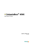
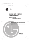
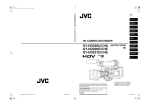
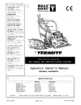
Lochinvar
®
INSTALLATION & OPERATION MANUAL
HARMONY
TABLE OF CONTENTS
Function Chart................................................pg. 2
Harmony Overview......................................pg. 3
Panel Installation.........................................pg. 4
Using the Menus.....................................pg. 10
System Startup ........................................pg. 11
Operating Settings.....................................pg. 14
System Settings...........................................pg. 17
Stage Settings............................................pg. 22
Reset Settings............................................pg. 25
Troubleshooting.......................................pg. 27
Appendix.....................................................pg. 28
Index..............................................................pg. 30
Specifications................................................pg. 32
This manual attempted to be complete and accurate at the time of publication. Additional upgrades and new features may change
Harmony functions. Upgrades to this manual may occur at any time. Contact the factory for further details.
1
Harmony Function Chart
Depress the knob to move
forward through the menus and to
accept changes, rotate the knob
to change a setting's value
The digital display shows the system status,
set point, lead stage <in brackets>, and
status of each stage. To view and adjust
settings, press the Adjust/Select button
Depress the button to go back
through the menus, or to view a
setting value without changing it
FULL MODULATION
SEQUENCING CONTROL
HARMONY
DO NOT APPLY ANY VOLTAGE
TO SENSOR TERMINALS
INPUTS
MENU FUNCTIONS
T
A1
ADJUST
A2
181
SELECT enters menus or accepts changes
SYSTEM
TEMP
A3
SHUTDOWN
ADJUST selects menu items or changes settings
A4
PRESS TO
SELECT
BACK returns to previous menu
<A>
B
C
D
STAGE selects stage menus or next stage
100
52
OFF
STBY
BACK
PREV/NEXT steps through stage settings
A5
+
A6
S
NETWORK
A9
A10
STAGE
PREV.
A11
NEXT
A12
BURNER
ACTIVE
B1
A
B
C
D
B3
B5
B7
SIGNAL
SHIELD
2
3
4
5
6
7
8
9
10
OUTDOOR
TEMP
Optional sensor enables
outdoor reset
If input is not made,
the Harmony will not
consider it an active
stage*
STAGE
D
B8
1
Checks status of system
components*
STAGE
C
B6
+
SYSTEM
PROVE
STAGE
B
B4
EMS INPUT
T
To network sensors**
STAGE
A
B2
SYSTEM
When closed, all stages
are turned off*
A7
A8
HELP
To Temp sensor mounted
in common header
12
11
C1
C2
C3
C4
C5
C6
C7
C8
C9
C10 C11 C12
C
LINE
NEUTRAL
A
SAFETY
GROUND
MUST BE
CONNECTED
SYS
A
B
C
D
B
C
D
MODULATION OUTPUTS
OPERATING LIMIT
OUTPUTS
MADE IN U.S.A.
Green Ground
screw must be
connected to
Earth Ground
System Output
controls pumps,
valves or other system
components
120VAC
Power
One output relay is required for
each stage.
Each N.O. output is
wired in series with
each unit's limit circuit
* DRY CONTACTS ONLY
** Only available with the Remote Communications package
2
The modulation outputs can be 0-5V, 0-10V,
1-5V, 2-10V, or 4-20ma. Different output
boards mount on the back of the Harmony
and determine the type of output.
Provides remote set
point adjustment with
a 4-20mA signal
Harmony Overview
Sequences up to 4 Fully Modulating Stages
The Harmony is the perfect control whenever multiple fully modulating stages are required. The Harmony controls the on/
off and the modulation of each stage to maintain precise set point control.
PID Type Logic
The Harmony's control algorithms allow it to look at the rate of change in the system. If the system temperature is
changing quickly, the Harmony will react quickly to adjust the modulating stages' output. If the system temperature
changes slowly, the Harmony will make slow and gradual adjustments. Therefore, the Harmony adapts to specific system
requirements and minimizes fluctuations around the set point.
Controls 0-5 V, 0-10 V, 1-5V, 2-10V, or 4-20 mA modulating motors
The Harmony is designed to accurately control the output from 0 to 100% of modulation for each of these different types
of motors. One Harmony can even control two different types of motors.
Only One Sensor
The Harmony requires only one sensor located in the common output header of all stages.
Digital Display of all System Settings
The Harmony's 80 character alphanumeric digital display names each system parameter in plain English and shows its
precise value. The easy to follow menu system allows users to quickly make changes to any system setting without
having to learn any specialized codes or keyboard commands. Password protection is available to prevent unauthorized
users from making adjustments to control settings.
Automatic Rotation among Stages
Rotating the first stage to be activated on a call for output promotes even wear on each stage. The Harmony has three
modes of rotation: Manual, First ON/First OFF, or automatically each time period which can be adjusted from every hour
to every 7 days.
Outdoor Reset Control
The Harmony has an optional stand-alone hydronic outdoor temperature reset function.
Connects to Energy Management Systems
The Harmony can accept a 4-20 mA input signal from an EMS to adjust the temperature set point according to outdoor
temperature, system requirements, or other factors. In addition, Harmony can be disabled by an Energy Management
System (EMS) or other controller when there is no output requirement.
Monitors Stage Status
The Harmony is designed to accept a lockout signal from each stage. If any stage requires a manual reset, the Harmony
will automatically skip it when adding more capacity. If a stage goes into lockout during normal operation, the next stage
will be activated immediately to maintain the desired output capacity.
System Output is Active when Any Stage is Active
This output can be used to activate a system pump, combustion air damper, or perform any other function that is required
when any stage is active. A System Prove input checks the status of components activated by the System output before
stages can be activated.
Remote Communication Upgrade Available
The Harmony can be upgraded to the Visual Gold system to monitor and control all Harmony functions from a remote
location. The Visual Gold upgrade also allows the Harmony to accept additional sensors, to monitor their status, and to
provide alarms if the sensor values are not in the correct range.
Additional features include: A purge timer, a low fire adjustment, a firing point setting for the next stage based on the
firing rate of the current stage, a lag stage timer, a last stage hold adjustment, and many others.
3
INSTALLA
ALLATION
INST
ALLA
TION INPUT WIRING
INSTALLATION
MOUNTING THE ENCLOSURE
• Select a location near the equipment to be controlled.
• The surface should be flat, and be sufficiently wide and strong to
hold the Harmony.
• Keep the Harmony panel away from extreme heat, cold, or humidity.
Ambient operating temperature is from 20 to 120°F.
• Remove the panel from the metal enclosure by removing the top
center screw and loosening the two bottom screws. Lift the panel
out.
• Screw the enclosure to the surface through the mounting holes in
the back of the enclosure.
• Return the panel to the enclosure, replace the top screw, and tighten
the bottom two screws.
Mounting Holes
Earth
Ground
2
NEUTRAL
SAFETY
GROUND
MUST BE
CONNECTED
1
LINE
WIRING THE POWER
3
4
SYS
120VAC
60 Hz
• Bring the 120VAC 60Hz power wires through a bottom Knockout
(KO) of the enclosure. The left front KO is preferred.
• Class 1 voltages must enter the enclosure through a different
opening from any Class 2 voltage wiring.
• Connect the hot line to terminal marked LINE.
• Connect the neutral line to the terminal marked NEUT.
• The green ground screw MUST be connected to earth ground.
INPUT WIRING
CONNECTING THE SYSTEM SENSOR
• The Harmony is designed to be connected to a
temperature sensor for immersion in a 3/8ID well.
Contact the factory for additional temperature sensor options.
INPUTS
A1
T
TEMP
A2
A3
SHUTDOWN
A4
A5
+
A6
S
A7
NETWORK
A8
A9
A10
4
SYSTEM
PROVE
To Temperature
Sensor Mounted in
Common Header
• Locate the sensor in a common header where it will register the
output of all the stages in the flow and after all stages have fed the
header. If the sensor can not read the output of all the stages, it will
not be able to control the system properly.
• Temperature sensor wires can be extended up to 500’ by splicing
with 18 gauge shielded wire (Belden #8760 or equivalent).
• Do not run sensor wire in conduit with line voltage.
• Temperature sensors have no polarity. Connect the wires from the
sensor to the Harmony terminals marked TEMP- A1, A2.
• Connect the shield to the circled terminal TEMP-A2 with one of the
sensor wires.
Note: Cut the shield wire at the sensor end.
EMS INPUT
+
SIGNAL
SHIELD
(-) EMS
(+) Input
EMS Sourcing Current
EMS INPUT
+
SIGNAL
SHIELD
(-) EMS
(+) Input
CONNECTING AN EXTERNAL SET POINT
(4-20mA EMS-CONTROL)
• The Harmony can take a 4-20mA signal from an Energy Management System (EMS) or other signal source to change the set point
remotely (see pg. 28 for additional details).
• The signal must be a two-wire 4-20mA.
• A system sensor must be installed as described in the previous
section.
• The External Set Point must be set up correctly (see pg. 12). These
settings will allow the Harmony to read and monitor the system
temperature and also monitor the 4-20mA input to remotely adjust
the Harmony set point to the desired value.
• The Harmony can source the current for the 4-20mA input. It
provides an excitation voltage of 24VDC. If using the Harmony to
source the power, attach the (+) side of the 4-20mA input to the
Harmony EMS terminal marked +. Attach the (-) side of the 4-20mA
signal to the EMS terminal marked SIGNAL.
• If the EMS or other signal sources the current (provides the
excitation voltage), attach the (+) side of the 4-20mA input to the
Harmony EMS terminal marked SIGNAL. Attach the (-) side of the
4-20mA input to the EMS terminal marked SHIELD.
WIRING THE SHUTDOWN
INPUTS
A1
T
TEMP
A2
A3
SHUTDOWN
A4
A5
+
A6
S
A7
NETWORK
A8
A9
A10
SYSTEM
PROVE
Dry Contact
Shutdown
Signal
• This feature can be used whenever it is desirable to turn off the
Harmony from a remote location or another controller.
• A typical use for this feature would be to turn off all boiler stages
when an EMS panel no longer requires heat in the system.
• When the Shutdown feature is enabled by closing a dry contact, all
active stages will immediately modulate down to low. They will
remain in low for 45 seconds and then turn off.
• If the System Output relay was active, it will remain active until the
System Delay is over, then it will also turn off.
• The Shutdown signal must be a dry contact only. No voltage can
be placed across the SHUTDOWN terminals.
• Bring the two wires from the dry contact to the terminals marked
SHUTDOWN- A3, A4.
WIRING THE SYSTEM PROVE
5
INST
ALLA
TION INPUT WIRING
INSTALLA
ALLATION
Harmony Sources Current
24VDC Excitation Voltage
INPUTS
INST
ALLA
TION INPUT WIRING
INSTALLA
ALLATION
A1
T
TEMP
A2
A3
SHUTDOWN
A4
A5
+
A6
S
A7
NETWORK
A8
A9
A10
SYSTEM
PROVE
Dry Contact
System Prove
Signal
WARNING: The SYSTEM PROVE
input can not be used as a safety
limit. All equipment must have its
own certified limit and safety controls as required by local codes.
• The System Prove feature is provided to check system component
operation.
• A typical use of this feature is to check for flow before firing any
boiler stages. When there is a call for heat, the System Output
activates the system pump starter. When the pump establishes flow,
a flow switch closes together the SYSTEM PROVE input. Only then
can the Harmony activate boilers and modulate them as required to
hold the temperature set point.
• If the SYSTEM PROVE input is open on a call, the Harmony will
enable only the System Output. All Stage outputs will be off when
the SYSTEM PROVE input is open.
• A factory installed jumper provides the System Prove signal. Do not
remove the jumper unless it will be replaced by a System Prove
signal.
• The System Prove signal must be a dry contact only. No voltage can
be placed across the SYSTEM PROVE - A9, A10 terminals.
• Bring the two wires from the dry contact to the terminals marked
SYSTEM PROVE - A9, A10.
IMPORTANT: Do not remove the factory installed System Prove
jumper unless it is replaced by a System Prove signal. If the
SYSTEM PROVE input is not closed, the Harmony will NOT
activate stages.
WIRING THE BOILER ACTIVE INPUTS
BOILER
ACTVE
INPUTS
B1
B2
B3
B4
B5
B6
B7
B8
STAGE
A
Dry Contact
Active Signal
STAGE
B
STAGE
C
STAGE
D
WARNING: The BOILER ACTIVE INPUTS can not be used as a safety
limits. All equipment must have its
own certified limit and safety controls as required by local codes.
6
• A closure across the BOILER ACTIVE terminals informs the Harmony that a boiler is running normally. If the BOILER ACTIVE
terminals open, the Harmony registers that the Stage has encountered a safety limit and can not be restarted without a manual reset.
The Harmony will not reactivate or modulate a Stage which is not
Active.
• The Boiler Active signal is not a safety, but use of these inputs will
significantly improve the Harmony's set point control performance in
the event of a Stage encountering a safety limit.
• A pair of BOILER ACTIVE terminals is provided for each stage.
• The Boiler Active signal must be a dry contact closure from the
boiler controlled by that Stage's output. For example, the Boiler
Active signal wired into terminals STAGE A (Terminals B1 and B2)
must come from the unit whose operating limits are connected to
terminals OPERATING LIMIT OUTPUTS A (Terminals 5 and 6).
• The BOILER ACTIVE terminals are dry contacts only. No voltage
can be placed across the them.
• Wire the Boiler Active signals to their respective STAGE terminals:
- STAGE A to Boiler Active Input terminals B1&B2
- STAGE B to Boiler Active Input terminals B3&B4
- STAGE C to Boiler Active Input terminals B5&B6
- STAGE D to Boiler Active Input terminals B7&B8
EMS INPUT
+
SIGNAL
SHIELD
Dry Contact
Setback
Signal
• The Setback feature can be used to provide the Harmony with a
lower temperature Set Point when less load is required.
• A typical use for Setback is to lower the system temperature during
the night or on the weekends when a building is unoccupied, but a
minimum level of heat is still required.
• The Setback feature can not be used with External Set Point (4-20mA
EMS-control) or Reset operation (see Startup Settings, pg. 11).
• To adjust the amount of Setback see pg. 19.
• The Setback signal is wired into the EMS terminals (Terminals
SIGNAL and SHIELD).
• The Setback signal must be a dry contact only. No voltage can be
placed across the EMS SIGNAL and SHIELD terminals.
• When the EMS SIGNAL and SHIELD are closed, the Setback is
enabled and the Harmony will hold the lower Set Point. The lower Set
Point will appear on the main display indicating this condition.
• When the closure is removed, the Harmony will revert to the higher
saved Set Point.
Note: The Setback is not equivalent to the 4-20mA input, even though
both wire into the EMS terminals. The 4-20mA input requires a 420mA source which changes the Set Point in one degree increments.
The Setback provides a single lower Set Point.
CONNECTING AN OUTDOOR SENSOR
For Reset Operation
• To enable the reset function, see System Startup settings, pg. 11.
For Outdoor Cutoff
A5
+
A6
S
• The Harmony will disable all stages when the outdoor temperature is
above the adjustable Outdoor Cutoff temperature.
• This feature will automatically be activated when an outdoor sensor
is connected.
• To adjust the Outdoor Cutoff temperature see pg. 26.
A7
NETWORK
A8
A9
SYSTEM
PROVE
A10
A11
A12
T
OUT
TEMP
Installing the sensor
• For outdoor sensor use the outdoor sensor.
• Locate the sensor in the shade on the north side of the building
• Be sure the location is out of direct sunlight, and away from doors,
windows, exhaust fans, vents, or other possible heat sources
To Outdoor
• The sensor should be mounted at least 4 inches away from the
Sensor Mounted
building wall and approximately 10 feet above ground level
in Shade
• The sensor wires can be extended up to 500' using shielded 2
conductor cable (Belden #8760 or equivalent).
• Do not run sensor wires in conduit with line voltage wiring.
• Temperature sensors have no polarity. Connect either wire from the
outdoor sensor to one of the Harmony terminals marked OUTDOOR
(Terminals A11&A12).
• Connect the other sensor wire to the other OUTDOOR terminal.
• Connect the shield to the circled terminal OUTDOOR (Terminal A12)
with one of the sensor wires.
OUTPUT WIRING
7
INSTALLA
ALLATION
INST
ALLA
TION INPUT WIRING
WIRING A SETBACK
INST
ALLA
TION OUTPUT WIRING
INSTALLA
ALLATION
WIRING THE SYSTEM OUTPUT
1
2
LINE
NEUTRAL
System Output Operation in Set Point Mode
3
4
SYS
5
6
A
7
8
B
N.O. contacts to activate a pump,
valve or other system component
9
10
C
• The SYS output relay will energize whenever there is a call for output
and the Shutdown feature is not active.
• Until the SYSTEM PROVE input is shorted, no Stages will be
activated. If a Prove is not required, the factory installed jumper
should remain.
• The SYS will remain energized while any Stage is active.
• When the last Stage relay turns off, the SYS output can remain
energized for the period of time set by the System Run-On (see pg.
19)
• A typical use of the SYS output is to activate a system pump starter.
The pump can run whenever there is a call for heat. When heat is no
longer required, the pump will stay active for a few more minutes to
remove the residual heat from the boilers.
System Output Operation in Reset Mode
• The SYS output relay will energize whenever the outdoor temperature is below the Outdoor Cutoff.
• The SYS will remain constantly energized while the outdoor temperature is below the Outdoor Cutoff.
• When the outdoor temperature rises 2°F above the Outdoor Cutoff,
the SYS output will remain energized for the period of time set by the
System Run-On (see pg. 19).
Wiring the SYS Output
• The SYS output has one Normally Open (N.O.) relay contact.
• The N.O. contacts are dry contacts only. They do not source any
voltage.
• Class 1 voltages must enter the enclosure through a different
opening from any Class 2 voltage wiring.
• Each N.O. contact is capable of switching 6A resistive at 120VAC.
• Total output SYS and the OPERATING LIMIT OUTPUTS must not
exceed 15A.
WIRING THE STAGE OUTPUTS
Installing the Output Relays
• Each output stage (A through D) which is to be used must have a
relay installed in the socket.
The SYS relay is included with the Harmony.
• To install a relay, orient the pins and then press it gently into the
appropriate socket.
• Any stage output which does not have a relay must have its Mode
set to Off (see Stage Settings pg. 22).
8
3
4
5
7
6
9
8
12
10 11
C
SYS
A
B
C
D
OPERATING LIMIT
OUTPUTS
• Each Stage output (A through D) has one Normally Open (N.O.)
relay contact.
• The N.O. contacts are dry contacts only. They do not source any
voltage.
• Each N.O. contact is capable of switching 6A resistive at 120VAC.
• Total output of all stages, including the SYS, must not exceed 15A.
• Wire the N.O. relay contacts in series with the boiler’s limit circuit.
• Class 1 voltages must enter the enclosure through a different
opening from any Class 2 voltage wiring.
Limit Circuit
Typical for each stage
WIRING TO 4-20 MA MODULATING MOTORS
4-20 mA
MODULATION OUTPUTS
Common Common Common Common
mA
mA
mA
mA
C1
C4
C2 C3
C5
A
-
C6 C7
C8 C9 C10 C11 C12
B
C
• The Harmony can be equipped to operate up to four 4-20 mA
modulating motors.
• To program the control for 4-20 mA output, see System Startup
settings, pg. 12.
• Apply the supplied label marked 4-20 mA below the output terminals.
• The output boards are connected on the rear of the panel.
• The pair of outputs A and B are controlled by a one output board.
The pair of outputs C and D are controlled by a second output
board.
• The Harmony sources 24VDC excitation voltage for the 4-20mA
signal.
• Wire as shown below:
Common
mA Source (+)
Stage A
C1
C2
Stage B
C4
C5
Stage C
C7
C8
Stage D
C10
C11
D
+
Harmony
Sources
Current
4 - 20mA
Motor
WIRING TO VOLTAGE MODULATING MOTORS
Voltage
MODULATION OUTPUTS
V+
V+
GND
GND
C1
C2 C3
C4
V+
GND
C5
C6 C7
V+
GND
C8 C9 C10 C11 C12
A
B
C
D
0- 5 V
or
0-10V
Motor
0- 5 V
or
0-10V
Motor
0- 5 V
or
0-10V
Motor
0- 5 V
or
0-10V
Motor
A
B
C
D
• The Harmony can be equipped to operate up to four 0-5 V, 0-10V, 15V, or 2-10V modulating motors.
• Apply the supplied label marked Voltage below the output terminals.
• The output boards are connected on the rear of the panel.
• To select the range, 0-5V, 0-10V, 1-5V or 1-10V, see pg. 12.
• The pair of outputs A and B are controlled by a one output board.
The pair of outputs C and D are controlled by another output board.
• Wire as shown below:
GND
V+
Stage A
C1
C3
Stage B
C4
C6
Stage C
C7
C9
Stage D
C10
C12
9
INSTALLA
ALLATION
INST
ALLA
TION OUTPUT WIRING
Wiring the Stage Outputs
USING MENUS
MAKING SELECTIONS
--- LEAD STAGE --->A This pointer shows the currently
B
selected item
C
The BACK button returns to a previous
menu without changing the
BACK
selection
ADJUST
Pressing
The ADJUST/SELECT knob
saves the selection to memory
PRESS TO
and returns to a previous menu
SELECT
ADJUST
Rotating
The ADJUST/SELECT knob
moves the pointer up and down
PRESS TO
selections
SELECT
Example: CHANGING VALUES
--- PURGE DELAY
---
1.0item
min
selected
The Purge Delay is currently 1 minute
The BACK button returns to a previous
menu without changing the value
BACK
ADJUST
--- PURGE DELAY
---
1.0 min -> 2.0 min
The screen shows the old and new value
Pressing
The ADJUST/SELECT knob
saves the new value (2.0 min) to
PRESS TO memory and returns to a
SELECT
previous menu
The BACK button returns to a previous
menu without changing the value
BACK
10
MENU TYPES
System Startup Settings - determines the type of system. For example,
the system is a hot water heating system with 0-10V modulating
motors. If the Startup Settings are not correct, the Harmony can not
operate the system correctly.
Set Point/Gain/Lead Stage Settings - These settings might need
occasional adjustment by operating personnel. These are the only
settings which may require changes after the Harmony has been
successfully initialized for your specific type of system.
Stage Settings - determine how the individual Stage outputs are
controlled. When installing the panel, each Stage must be set
correctly, or the Harmony either will not control the Stage or will
control them erratically.
System Settings - determine how the system will operate. These are
general settings which affect all Stages. The default settings will
generally work in most applications, but adjustments should be made
to fine-tune the performance of your system.
MENU BASICS
• The menus are in English and will guide you through the settings.
• To change a selection, rotate the black knob marked ADJUST and
PRESS TO SELECT (ADJUST/SELECT). Rotating the knob clockwise will move down the list of possible selections. Rotating the
knob counterclockwise will move up the list.
• A pointer in front of a menu line indicates that it is the one currently
selected.
• When the pointer is on the same line as the item to be selected, press
the black ADJUST/SELECT knob. This will either save the selection,
or bring up a new screen to make further changes to that menu item.
• The BACK button will return you to the previous screen without
saving any changes made.
Rotating
The ADJUST/SELECT knob
changes the value - this is
PRESS TO indicated by a pointer from the
SELECT
old value to a new value
ADJUST
USING THE MENUS
CHANGING SETTINGS
• Some settings require a number, such as time or temperature to be
adjusted.
• These screens will be indicated with the title on top and then the
current numerical value for that setting.
• To change a selection, rotate the ADJUST/SELECT knob. Rotating
the knob will cause a pointer to appear. Both the old and new value
will be displayed.
• The BACK button will return you to the previous screen without
saving any changes made.
• When the new value (the one being pointed to) is correct, press the
ADJUST/SELECT knob. This will save the selection to memory and
return you to the previous menu.
Self Test...
STARTUP SEQUENCE
• The series of initialization screens appears on the left. The Harmony
will automatically step through the screens.
• When powered, the Harmony performs a self test on its components.
• After the self test diagnostics have been successfully completed,
the Harmony will initialize the panel.
• On the first powerup, the System Startup screen will appear after the
initialization is complete. If it doesn't, the Harmony has already been
configured. To check the configuration, or to make changes, follow
the procedure on pg. 28 to bring up the System Startup screens.
• The System Startup menu determines the sensors, the type of
output, the operating mode, and the modulating mode.
• Press the ADJUST/SELECT knob once to begin setting up the
panel.
Test Passed
Initializing...
Lochinvar
Harmony v X.XX
Initialization
Please wait...
INITIALIZING
PERMANENT STORAGE
AREA
Please wait...
-- SYSTEM STARTUP -SELECT
to continue
SELECTING THE SENSOR TYPE
--- SENSOR TYPE -->°F
°C
Check the installation and which sensor was installed
ADJUST
PRESS TO SELECT
--- SENSOR TYPE --°F
>°C
ADJUST
PRESS TO SELECT
--- SENSOR TYPE --°F
>°C
or turn
to scroll
down
Temperature Set Point Mode
Default - °F
• The same temperature sensor can display either in °F or °C.
• If °F is selected, all temperatures and settings will be displayed in
degrees Fahrenheit.
• If °C is selected, all temperatures and settings will be displayed in
degrees Celsius.
Reset Mode (Reset °F or Reset °C)
ADJUST
PRESS TO SELECT
--- SENSOR TYPE --°F
°C
Reset °F
Reset °C
Press to
select
°F
Press to
select
new
All Sensor
Type options
• Reset mode is only available if an outdoor sensor is connected to
terminals A11 and A12. DO NOT select Reset °F or Reset °C without
an outdoor sensor.
• The same outdoor sensor can display either in °F or °C.
• If Reset °F is selected, all temperatures and settings will be displayed in degrees Fahrenheit.
• If Reset °C is selected, all temperatures and settings will be displayed in degrees Celsius.
• For information on how to configure the Reset, see pg. 25.
11
SY
STEM ST
AR
TUP
SYSTEM
STAR
ARTUP
SYSTEM STARTUP
SY
STEM ST
AR
TUP
SYSTEM
STAR
ARTUP
---- EMS INPUT
>Setback
EMS-Control
---ADJUST
PRESS TO SELECT
---- EMS INPUT
>Setback
EMS-Control
ADJUST
---ADJUST
PRESS TO SELECT
or turn
to scroll
down
Press to
select
EMS
IMPORTANT: Do not select EMS-Control
unless an appropriately configured signal
from an EMS system is correctly wired into
the Harmony. For additional details, see pg.
5 for wiring, and pg. 28 for EMS-Control
setup.
- OUTPUT TYPE A&B
>4-20ma
0-10v
0-5v
-
- OUTPUT TYPE A&B
4-20ma
>0-10v
0-5v
-
- OUTPUT TYPE A&B
4-20ma
>0-10v
0-5v
-
- OUTPUT TYPE C&D
>4-20ma
0-10v
0-5v
-
EMS INPUT
Default - Setback
Not available for Reset Sensor Types
Setback
----
PRESS TO SELECT
---- EMS INPUT
Setback
>EMS-Control
Press to
select
Setback
ADJUST
PRESS TO SELECT
ADJUST
PRESS TO SELECT
ADJUST
PRESS TO SELECT
Press to
select
4-20ma
or turn
to scroll
down
Press to
select
new
Repeat
process for
Stages C&D
• This default setting allows the Set Point to be adjusted either
manually at the panel, or by a Visual Gold upgrade for remote
communications.
• If desired, a dry contact switch can be wired across the EMS INPUT
terminals SIGNAL and SHIELD to allow the panel to hold a lower
temperature Set Point when less load is required. To adjust the
amount of Setback, see pg. 19.
• When selecting Setback, there is no requirement for any wiring
across the EMS INPUT terminals. DO NOT select EMS-Control
unless your system meets the requirements below.
External Set Point (4-20mA EMS-Control)
• For this option, an EMS system must provide a 4-20mA signal to
automatically change the Set Point based on pre-programmed
system parameters.
• An active signal must be wired into the EMS Harmony terminals. If
the Harmony does not receive a signal between 3.9mA and 20.1mA,
it will NOT activate any stages.
• If your system meets the above two criteria, see pg. 28 to complete
the EMS-control setup.
SELECTING THE OUTPUT TYPE
• The Harmony has two output cards, one for stages A & B, and one
for stages C & D.
• Both output cards must be programmed for the appropriate mode of
operation.
• Outputs can be configured for 4-20mA operation (current) or the
voltage range can be selected (0-5V, 0-10V, 1-5V, 2-10V).
• Check the modulating motor to determine its control requirements.
• Select the appropriate Output Type for stages A & B. The Harmony
will then automatically bring up the screen for stages C & D.
• Select the appropriate Output Type for stages C & D.
• If different types of burners are being used, stages C & D can be
selected to have a different Output Type than stages A & B.
SELECTING THE MODULATING MODE
Default - Normal
- MODULATING MODE
>NORMAL
PARALLEL
ADJUST
PRESS TO SELECT
- MODULATING MODE
NORMAL
>PARALLEL
ADJUST
PRESS TO SELECT
- MODULATING MODE
NORMAL
>PARALLEL
ADJUST
PRESS TO SELECT
12
Press to
select
Normal
or turn
to scroll
down
Press to
select
Parallel
• Most boilers run more efficiently as their modulation increases.
Therefore, for most systems, it is more energy efficient to run one
boiler in high than several boilers at lower modulation. If your
system is of this type, select Normal.
• There are some systems were it may be more energy efficient to run
several units at lower modulation than one at high. If that is the case
select Parallel.
ADJUST
PRESS TO SELECT
-- OPERATING MODE -NORMAL
>PROCESS
ADJUST
PRESS TO SELECT
-- OPERATING MODE -NORMAL
>PROCESS
ADJUST
PRESS TO SELECT
Press to
select
Normal
or turn
to scroll
down
Press to
select
Process
SELECTING THE OPERATING MODE
Default - Normal
• Most heating applications do not experience rapid changes in
system temperature. For these systems, it is best to adjust the
modulation based on the rate of system rise or fall. This PID type of
algorithm will help to prevent short cycling of the stages, reduce
thermal stress on the system, and maintain an accurate system
temperature. If your equipment is of this type, select Normal.
• Systems that run for process may experience large changes in load
almost instantaneously. In Process mode, the Harmony will react
immediately to load changes. Large load changes may cause stages
to be short cycled, as the Harmony can enable and disable stages
within seconds.
After making this selection, the main display screen will be displayed.
13
SY
STEM ST
AR
TUP
SYSTEM
STAR
ARTUP
-- OPERATING MODE ->NORMAL
PROCESS
SET POINT
OPERATING SETTINGS
CHANGE SET POINT, GAIN, LEAD STAGE
Temperature
<A>
OFF
B
OFF
C
OFF
THE MAIN DISPLAY
D
OFF
--SETTINGS
>Set Point
Gain
Lead Stage
---
---
---
SET POINT
ADJUST
PRESS TO SELECT
ADJUST
Value
Press to
show
Settings
Press to
show
Set Point
• The main display screen may have different values in the top two
lines depending on the application.
• The third line shows the four stages. The Lead Stage will be in
brackets. For example, the Lead Stage shown at left is <A>.
• The last line shows the status of each stage. The stages may be Off
or the actual percent modulation will be displayed.
• To reach the Settings menu, press the ADJUST/SELECT knob and
release it.
PRESS TO SELECT
---
SET POINT
--ADJUST
Value -> New Value
PRESS TO SELECT
---
SET POINT
Turn to
adjust
value
SET POINT DISPLAY
Turn to
adjust
value
Outdoor Cutoff Temperature
--ADJUST
Value -> New Value
PRESS TO SELECT
If the optional Outdoor Sensor
is installed
-- OUTDOOR CUTOFF -ADJUST
Value -> New Value
PRESS TO SELECT
-- OUTDOOR CUTOFF -ADJUST
Value -> New Value
PRESS TO SELECT
SET POINT
Press to
select
new
• The Set Point is the temperature value the Harmony will use to
control the system.
• The Harmony will either increase the amount of modulation,
decrease the amount of modulation, or maintain the same amount of
modulation to maintain the system temperature around the Set Point.
• The Set Point is the target temperature the Harmony will maintain.
The system can be expected to fluctuate above and below the Set
Point. The size of the fluctuation depends on the number of stages,
the system load, and the Operating Mode selected (see pg. 13).
• If the outdoor sensor is installed (see pg. 7), the Outdoor Cutoff
screen will automatically appear after the Set Point has been
selected.
• When the outdoor temperature falls to the adjustable Outdoor
Cutoff temperature, the Harmony will control and modulate stages to
hold the temperature Set Point.
• When the outdoor temperature rises to the Outdoor Cutoff temperature plus a 2°F differential, the Harmony will disable the system.
RESET °F AND RESET °C
• The Set Point is based on the Reset Ratio, Offset, and Outdoor
Cutoff. To make these settings, see pg. 25.
EXTERNAL SET POINT (4-20mA EMS- CONTROL)
• The Set Point value can only be changed by adjusting the 4-20mA
input wired into the Harmony, see pg. 28.
• Rotating the ADJUST/SELECT button will have no impact on the
Set Point value.
14
---
--ADJUST
PRESS TO SELECT
GAIN
--ADJUST
Value -> New Value
PRESS TO SELECT
---
GAIN
--ADJUST
Value -> New Value
PRESS TO SELECT
Press to
show
setting
Turn to
adjust
value
Press to
select
new
GAIN/THROTTLE
OPERATING MODE - NORMAL
Default = 0
• The Gain adjusts the PID logic in the Harmony to control how much
modulation is changed when the system temperature is different
from the Set Point.
• A Gain of 0 is a good starting point for all systems.
• If, during normal load conditions, the system temperature tends to
fluctuate significantly above and below the Set Point, decrease the
Gain by two numbers (for example, from 0 to -2). Wait for at least 15
minutes before evaluating how the change has affected the system.
• If, during normal load conditions the system temperature tends to
remain consistently below the Set Point (or consistently above the
Set Point), increase the Gain by two numbers (for example, from 0 to
2). Wait for at least 15 minutes before evaluating how the change has
affected the system.
OPERATING MODE - PROCESS
Default = 1.0
• The Gain acts as a throttling range around the Set Point.
• When the actual temperature is equal to the Set Point, the lead stage
will be at 100% modulation.
• Each throttling range above or below the Set Point controls one
stages modulation linearly from 0 to 100%.
• The Process Gain Table below shows the relationship between the
Gain and stage modulation.
• The Process Gain Table does not show all the possible modulation
values. The table is for example only. The Harmony will control the
modulation in one percent increments based on the Set Point and
Gain value.
PROCESS GAIN/THROTTLING RANGE TABLE
SYSTEM TEMPERATURE
STAGES MODULATION
3 x Gain Setting Above Set Point
All Stages OFF
2.5 x Gain Setting Above Set Point
All Stages OFF
2 x Gain Above Set Point
Lead Stage at 0%
1 x Gain Above Set Point
Lead Stage at 0%
0.5 x Gain AboveSet Point
Lead Stage at 50%
At Set Point
Lead Stage at 100%
0.5 x Gain Below Set Point
Lead Stage at 100%, 1 Lag at 50%
1x Gain Below Set Point
Lead and 1 Lag at 100%
2 x Gain Below Set Point
Lead and 2 Lag at 100%
2.5 x Gain Below Set Point
Lead and 2 Lag at 100%
3 x Gain Below Set Point
All Stages at 100%
15
GAIN - THR
OTTLE
THRO
--SETTINGS
Set Point
>Gain
Lead Stage
LEAD ST
AGE
STA
LEAD STAGE
--SETTINGS
--Gain
>Lead Stage
<Stage Settings>
--- LEAD STAGE
>A
B
C
----
--- LEAD STAGE
A
>B
C
----
16
ADJUST
PRESS TO SELECT
ADJUST
PRESS TO SELECT
ADJUST
PRESS TO SELECT
Press to
show
setting
Turn to
adjust
value
Press to
select
new
Used to manually change the lead stage
• The Lead Stage is the first stage brought on when output is
required.
• The Lead Stage can be rotated manually or automatically. The
automatic rotation is recommended (see pg. 17).
• The current Lead Stage is shown in brackets on the main display.
• Only Stages which are set to Auto Mode can be Lead. Therefore,
not all the stages may be available when manually selecting a new
Lead Stage.
<A>
OFF
B
OFF
C
OFF
--SETTINGS
>Set Point
Gain
Lead Stage
D
OFF
THE SYSTEM SETTINGS MENU
--ADJUST
PRESS TO SELECT
--SETTINGS
--Gain
Lead Stage
><System Settings>
- SYSTEM SETTINGS 1>Auto Rotate
Purge Delay
Lag Delay
Press to
show
Settings
ADJUST
PRESS TO SELECT
ADJUST
PRESS TO SELECT
Turn to
scroll
down
• These are general settings which affect all Stages and overall
operation.
• The Harmony will generally operate satisfactorily with the default
settings. However, it is recommended that each of these settings be
checked on Startup to tune the Harmony to the particular system.
• From the main display, press the ADJUST/SELECT knob and release
it to reach the Settings display.
• Scroll down to <System Settings> and select it.
• The System Settings 1 menu will be shown.
Press
for
menu
SYSTEM SETTINGS 1
AUTO ROTATE
- SYSTEM SETTINGS 1>Auto Rotate
Purge Delay
Lag Delay
- LEAD AUTO ROTATE >Manual
Time
Lst on
--- LEAD STAGE
Manual
>Time
Lst on
ADJUST
PRESS TO SELECT
ADJUST
PRESS TO SELECT
---ADJUST
PRESS TO SELECT
Press to
show
setting
Turn to
scroll
down
Press to
select
new
Default - Time
• The Lead Stage will always be the first stage activated when there is
a call for output.
• Automatically rotating the Lead among the active stages promotes
more even wear on the Stages and can help prolong the life of each
unit.
• The Lead Stage is shown on the main display in brackets.
• The Harmony has three selections for rotating the Lead Stage. Each
is described below.
Manual
• If Manual is selected, the Lead Stage will not automatically rotate.
• In Manual, whichever stage is presently the Lead Stage will remain
the Lead Stage until there is a power failure. Then the Harmony will
revert back to the lowest Stage in Auto Mode (that is, A first, then
B, C, or D).
Time
• On power up, or any time the Harmony loses power, the Lead Stage
will be the lowest stage in Auto Mode (that is, A first, then B, C, or
D).
• If the default 24 hour rotation is used, at 2 am every morning, the
Lead Stage will change to the next stage in Auto Mode. Note: If you
do not set the system time (see pg. 21), the Harmony will assume it
was installed at 2 pm.
• If the Rotate Time is changed (see pg. 20), the Lead Stage will
change to the next stage in Auto Mode every time the Rotate Time
has elapsed. For example, with a 12 hour Rotate Time, the Lead Stage
will rotate from A to B after the first 12 hours of operation, and then
from B to C after the next 12 hours, and so on.
• The Lead Stage will always be the first stage brought on and
modulated when there is a call for output. As more output is needed,
additional Stages are added.
• When less output is needed, the additional Stages are turned off in
the reverse order of how they were added. For instance, if the
stages were added in the sequence A, B, and C, then they will be
turned off in the sequence C, B, and finally A.
17
SY
STEM SETTINGS 1
SYSTEM
SYSTEM SETTINGS
Temp
SY
STEM SETTINGS 1
SYSTEM
Lst on
• On power up, or any time the Harmony loses power, the Lead Stage
will be the lowest stage in Auto Mode (that is, A first, then B, C, or
D).
• The Lead Stage will always be the first stage brought on and
modulated when there is a call for output. As more output is needed,
additional stages are added.
• When less output is needed, the Lead Stage will be the first stage
turned off. The bracket indicating lead stage will then switch to the
next available stage in Auto Mode. For instance, if the stages were
added in the sequence A, B, and C, then they will be turned off in
the sequence A, B, and finally C. The lead stage will now be D when
more output is needed.
PURGE DELAY
- SYSTEM SETTINGS 1Auto Rotate
>Purge Delay
Lag Delay
--- PURGE DELAY
ADJUST
PRESS TO SELECT
--ADJUST
Value -> New Value
PRESS TO SELECT
--- PURGE DELAY
--ADJUST
Value -> New Value
PRESS TO SELECT
Press to
show
setting
Turn to
adjust
value
Press to
select
new
LAG DELAY
- SYSTEM SETTINGS 1Purge Delay
>Lag Delay
Standby Time
---
LAG DELAY
ADJUST
PRESS TO SELECT
--ADJUST
Value -> New Value
PRESS TO SELECT
---
LAG DELAY
--ADJUST
Value -> New Value
PRESS TO SELECT
18
Press to
show
setting
Turn to
adjust
value
Press to
select
new
Default - 1.0 min
• Most fully modulating units must go through a purge cycle before
they are brought on line and can begin generating heating.
• After activating a new Stage, the Harmony does not adjust its
modulation until the Purge Delay is over. This allows the unit to fully
come on line and to begin producing output. Once the Purge Delay
is over, the Harmony can begin adjusting its modulation to hold the
set point.
• The Purge Delay helps to prevent short cycling of a newly activated
Stage. Once a Stage is activated, it MUST run through the entire
Purge Delay period.
• The minimum Purge Delay setting MUST be the time required for the
unit’s purge cycle.
• The actual Purge Delay should be set to the amount of time between
when a Stage is activated, and when the Harmony sensor begins to
see a change in output. This can be several minutes longer than the
actual purge time of the unit.
Default - 0 min
• Set the Lag Delay to 0 min when two or more Stages will generally
be needed to hold the load.
• The Lag Delay requires the previous stage to remain at 100%
modulation for the full period of the Lag Delay before another Stage
can be activated. For example, if the Lag Delay is set to 10 minutes,
the Lead Stage would need to remain at 100% modulation for a full
ten minutes (never backing down to even 99%) before a lag stage
could be activated.
• The Lag Delay is useful in installations where one unit should
usually have enough output to hold the load unless it fails or load
conditions become extreme.
• The Lag Delay overrides the value of the Modulation Point selected
for each stage. Regardless of that setting, the previous stage must
reach 100% and stay there before another Stage can be activated.
• The full Lag Delay must always elapse regardless of what happens
to system temperature. Therefore, set the Lag Delay to 0 min if you
want smooth set point control from multiple units.
-- STANDBY DELAY
ADJUST
PRESS TO SELECT
-ADJUST
Value -> New Value
PRESS TO SELECT
-- STANDBY DELAY
-ADJUST
Value -> New Value
PRESS TO SELECT
Press to
show
setting
Turn to
adjust
value
Press to
select
new
STANDBY TIME
SYSTEM RUN-ON
- SYSTEM SETTINGS 1Standby Time
>System RunOn
<More Settings>
-- SYSTEM RUN-ON
ADJUST
PRESS TO SELECT
-ADJUST
Value -> New Value
PRESS TO SELECT
-- SYSTEM RUN-ON
-ADJUST
Value -> New Value
PRESS TO SELECT
Press to
show
setting
Turn to
adjust
value
Press to
select
new
Default - 10 min
• The Standby Time only applies to Stages in Standby Mode.
• A Standby Stage can only be activated after all the Stages in Auto
Mode have run at 100% modulation for the full Standby Time.
• Standby Stages are used for backup up or extreme load conditions
only. A Standby Stage can never be a Lead Stage
• The full Standby Time must always elapse regardless of what
happens to system temperature. Therefore, shorter Standby Times
will result in smoother set point operation in extreme conditions.
Longer Standby Times will result in more loss of load, but may
prevent a Standby Stage from firing if the other stages can eventually meet the load, or if the load decreases.
Default - 0 min
• The SYS output relay will energize whenever there is a call for output
and the Shutdown feature is not active.
• The SYS will remain energized while any Stage is active. When the
last Stage relay turns off, the SYS output will remain energized for
the period of time set by the System Run-On.
• If the System Run-On is set to 0, the SYS output will turn off
immediately when the last Stage turns off.
• A common use of the SYS output is to control a system pump in a
heating system. After the last Stage is turned off, it is often desirable
to run the system pump for an additional period of time to transfer
the residual heat from the boilers to the heating system.
SYSTEM SETTINGS 2
SETBACK
- SYSTEM SETTINGS 1Standby Time
System RunOn
><More Settings>
- SYSTEM SETTINGS 2>Setback
Rotate Time
Last Stg Hold
---
SETBACK
ADJUST
PRESS TO SELECT
ADJUST
PRESS TO SELECT
--ADJUST
Value -> New Value
PRESS TO SELECT
---
SETBACK
--ADJUST
Value -> New Value
PRESS TO SELECT
Press to
show
more
Press to
show
setting
Turn to
adjust
value
Press to
select
new
Default - 0
• Setback is not available in the Reset, or 4-20mA EMS-Control mode.
• The Setback feature can be used to provide the Harmony with a
lower temperature Set Point when less load is required.
• The lower Set Point will appear on the main display indicating this
condition.
• A typical use for Setback is to providea lower system temperature to
a factory during the night or on the weekends when product is not
being manufactured but heat is still required.
• The Setback will not be activated unless a signal is wired into the
Harmony EMS terminals. See pg. 7 for wiring.
• The amount of Setback selected is subtracted from the Set Point
when a Setback signal is received.
• For a example, if the Set Point is 180°F and the Setback is 20°F, then
when the EMS SIGNAL and SHIELD terminals are closed, the
Harmony will hold a Set Point of 160°F.
19
SY
STEM SETTINGS 2
SYSTEM
- SYSTEM SETTINGS 1Lag Delay
>Standby Time
System RunOn
SY
STEM SETTINGS 2
SYSTEM
- SYSTEM SETTINGS 2Setback
>Rotate Time
Last Stg Hold
ADJUST
PRESS TO SELECT
-AUTO ROTATE PERIODADJUST
Value -> New Value
PRESS TO SELECT
-AUTO ROTATE PERIODADJUST
Value -> New Value
PRESS TO SELECT
Press to
show
setting
Turn to
adjust
value
Press to
select
new
ROTATE TIME
Default 24hr
• The Rotate Time only takes effect if the Auto Rotate type is Time
(see pg. 17).
• The default value is 24 hours and is appropriate for most systems.
With 24 hour rotation, at 2 am every morning, the Lead Stage will
change to the next stage in Auto Mode. Note: If you do not set the
system time (see pg. 21), the Harmony will assume it was installed at
2 pm.
• The Rotate Time is adjustable in one hour increments from 1 hour to
168 hours (7 days).
• If the Rotate Time is not 24, the Lead Stage will change to the next
stage in Auto Mode every time the Rotate Time has elapsed. For
example, with a 12 hour Rotate Time, the Lead Stage will rotate from
A to B after the first 12 hours of operation, and then from B to C
after the next 12 hours, and so on.
LAST STAGE HOLD
- SYSTEM SETTINGS 2Rotate Time
>Lst Stg Hold
Password
- LAST STAGE HOLD
ADJUST
PRESS TO SELECT
ADJUST
Value -> New Value
PRESS TO SELECT
- LAST STAGE HOLD
ADJUST
Value -> New Value
PRESS TO SELECT
Press to
show
setting
Turn to
adjust
value
Press to
select
new
IMPORTANT: The temperature limits set on
the boilers must be higher than the
Harmony Set Point. Read the section at
right for details that will prevent erratic
system operation.
20
Default 0
• The Last Stage Hold prevents short cycling of the Lead Stage
during low load conditions.
• Even at 1% modulation, most fully modulating units are outputting
at least 20% of their maximum output. Some units may be outputting
significantly more.
• In low load conditions, the system might require only 5% of the
output of one Stage. When the Harmony brings on the Lead Stage,
this is 20% of the output. The Set Point is quickly exceeded, and the
Harmony turns the Lead Stage off.
• To prolong the run time during this type of condition, use the Last
Stage Hold setting.
• The Harmony will allow the system temperature to exceed the Set
Point by the number of degrees selected, before the Lead Stage is
turned off.
• For example, with a Set Point of 160°F and a Last Stage Hold setting
of 20°F, the Lead Stage boiler will remain on, at low modulation, until
the Set Point reaches 180°F.
Avoiding Conflicting Boiler Limits
• The temperature limits set on the boilers MUST be set considerably
higher than the Harmony's Set Point for the reasons detailed below.
• The Harmony sensor is located in a common header some distance
from the boilers.
• As the water enters the header and travels to the sensor location,
energy is dissipated.
• Therefore, the temperature in the header will correctly be lower than
that registered by sensors in the boilers.
• In addition to the normal drop experienced between the boiler's
internal reading and that read by the Harmony sensor, the Last Stage
Hold setting must be accounted for. The boiler limit must be set
above the Set Point PLUS the Last Stage Hold PLUS the normal
drop experienced in the piping.
• Using the previous example of a Harmony Last Stage Hold with a
20°F Set Point, the boilers' limits must be set enough over 180°F to
prevent the boilers' internal limits being reached. In this situation,
the boiler high limit should be set at approximately 195°F to prevent
the difference in boiler temperature vs. header temperature causing
erratic operation.
ADJUST
PRESS TO SELECT
--LOGIN
--Enter password:
M***
ADJUST
PRESS TO SELECT
--LOGIN
--Enter password:
MM**
ADJUST
PRESS TO SELECT
CHANGE PASSWORD?
No
>Yes
ADJUST
PRESS TO SELECT
--
NEW PASSWORD -Enter password:
M***
ADJUST
PRESS TO SELECT
--LOGIN
--Enter password:
M***
ADJUST
PRESS TO SELECT
Turn to
adjust
Letter 1
Press to
select
Letter 1
Turn to
adjust
Letter 2
Press to
select
Yes
Turn to
adjust
Letter
Press to
select
Letter
After setting all letters
After setting all letters
-ADJUST
Password
changed!
Default Disabled
• The Password is provided to prevent unauthorized users from
making changes to the Harmony settings.
• Setting up the Password feature is not recommended as it slows
down access, makes servicing more difficult, and can disable the
system if management or ownership should change.
• The Password feature is not active unless a user enables it.
• If you choose to enable the Password, DO NOT forget the Password. Write it down and store it in a safe location known to at least
one other authorized user.
• When the Password is enabled, none of the settings can be
changed without entering the Password.
• Once the Password is entered, you can make multiple changes. The
Password will expire 15 minutes after the last change has been made.
Using the Default Password
• The Harmony has a built in default Password - MMOD.
• Enabling the default Password will prevent most unauthorized users
from adjusting the settings, but will not prevent Lochinvar service
personnel, or anyone else with access to this manual, from adjusting
the panel.
• To enable the default Password, enter the System Settings 2 menu,
select Password, and follow the prompts to enable the Password.
• At the Login screen, you will have to enter the Password. Turn the
ADJUST/SELECT knob until the desired letter is shown. Then
select the letter to move on.
• Enter MMOD into the Login screen as shown top left.
• When completed, select No to the prompt Change Password?
Changing the Password
-- NEW PASSWORD -RE-enter password
M***
-- !! SUCCESS !!
PASSWORD
PRESS TO SELECT
- SET PRESENT TIME ADJUST
2:00pm
PRESS TO SELECT
- SET PRESENT TIME ADJUST
11:**am
PRESS TO SELECT
- SET PRESENT TIME ADJUST
11:00am
PRESS TO SELECT
- SET PRESENT TIME ADJUST
11:45am
PRESS TO SELECT
Press to
finish
Turn to
adjust
hour
Press to
select
hour
• Follow the instructions to use the default Password, but select Yes
to the prompt Change Password?
• Enter your new Password in the New Password screen. Turn the
ADJUST/SELECT knob until the desired letter is shown. Then
select the letter to move on.
• Reenter the same new password when prompted.
• If the password is correctly entered, the Success screen will appear.
If you made a mistake, the procedure will need to be repeated.
SET TIME
• Setting the system time will set the default 24 hour rotation to occur
at 2 am every morning.
• To set the Time, enter the System Settings 2 menu, select Set Time.
• Turn the ADJUST/SELECT knob until the correct hour is shown. Be
sure that am or pm is set correctly. Then select the hour.
• Turn the ADJUST/SELECT knob until the correct number of
minutes is shown. Then select the minutes.
Turn to
adjust
minutes
Press to
select
minutes
21
SY
STEM SETTINGS 2
SYSTEM
--LOGIN
--Enter password:
M***
STAGE SETTINGS
ST
AGE SETTINGS
STA
Temp
<A>
OFF
B
OFF
C
OFF
INDIVIDUAL STAGE ADJUSTMENTS
D
OFF
Press
THE STAGE MENU
STAGE
- STAGE A SETTINGS >Mode
Ignition %
Mod Start %
After completing all
settings for Stage A Select Stages B, C, and D
Press
STAGE
- STAGE B SETTINGS >Mode
Ignition %
Mod Start %
• In most installations, all Stage adjustments are the same, but each of
the four output Stages can be configured differently if desired.
• If the stages are not set up properly, the Harmony operation may
appear to be erratic.
• From the main display, press the STAGE button and release it.
• The Stage A Settings menu will be shown.
• Make all the appropriate settings for Stage A as described below
and on the following two pages.
• After completing all the settings for Stage A, you have the option of
copying these settings to all other Stages. Everything but the Mode
-- Auto/Standby/Manual/Off/On -- will be copied.
• Then press the STAGE button to bring up the Stage B Settings
menu and make all the settings. Continue until all four stages have
been set.
• To move around the Stage Menus more easily, see pg. 29.
IMPORTANT: When initializing the panel,
the MODE for all four Stages
MUST BE SET
- STAGE
SETTINGS >Mode
Ignition %
Mod Start %
--- STAGE
Manual
>Off
On
MODE ---
--- STAGE
>Auto
Standby
Manual
MODE ---
--- STAGE
>Auto
Standby
Manual
MODE ---
--- STAGE
Auto
Standby
Manual
Off
On
MODE ---
22
ADJUST
PRESS TO SELECT
ADJUST
PRESS TO SELECT
ADJUST
PRESS TO SELECT
ADJUST
PRESS TO SELECT
Press to
show
Mode
Press to
select
Off
or turn
to scroll
down
Press to
select
new
All Mode
Options
MODE
Default - OFF
Auto/Standby/Manual/Off/On
• The Harmony only controls the modulation of Stages set to Auto or
(after a delay) those set to Standby. None of the other settings are
recommended for output Stages connected to active units.
• Any Stage without an active unit connected, and/or without an
output relay must be set to Off.
• The following list describes the MODE options:
Auto - The Harmony will control the Stage's operation to maintain
the Set Point. Only Stages set to Auto can be Lead Stages.
Standby - Standby Stages can only be activated when all Stages in
Auto have been at 100% modulation for a selectable period of
time (see pg. 14). Standby is generally used when an older or less
efficient unit is available, but is not desired to run except under
extreme load conditions. A Standby Stage CAN NOT be a Lead
Stage.
Manual - The Manual Mode should only be used when testing a
Stage. Manual overrides the System Prove input (see pg. 6). The
exact percent of modulation for a Stage can be set with the
Manual mode. Once selected, the unit will immediately turn on
and be modulated to the selected percentage.
Off - Any output Stage A through D without a relay, or not connected to a physical unit should be set to Off. The Off Mode can
also be used to disable units which are being serviced.
On- The On Mode should only be used when testing a Stage. The
On Mode overrides the System Prove input (see pg. 6). Once
selected as On the Stage will immediately turn on and be modulated to 100%.
ADJUST
PRESS TO SELECT
----- STAGE
-----IGNITION POINT
Value -> New Value
ADJUST
PRESS TO SELECT
----- STAGE
-----IGNITION POINT
Value -> New Value
ADJUST
PRESS TO SELECT
Press to
show
setting
Turn to
adjust
value
Press to
select
new
IGNITION POINT
Default - 1%
When Can a Stage Begin Modulating?
• The Ignition Point is the percent modulation which must be attained
before the unit can be activated.
• For most boilers, the Ignition Point should be set at 1%.
• Older units or atmospheric units may require the modulating fuel
valve to be open from 20-50% before proper ignition can be attained.
Check with the boiler manufacturer if you are in doubt about the
minimum position of the fuel valve for ignition.
MODULATION START
Default - 75%
When Does the Next Stage Turn On?
- STAGE
SETTINGS Mode
Ignition %
>Mod Start %
ADJUST
PRESS TO SELECT
----- STAGE
-----MODULATION START
Value -> New Value
ADJUST
PRESS TO SELECT
----- STAGE
-----MODULATION START
Value -> New Value
ADJUST
PRESS TO SELECT
Press to
show
setting
Turn to
adjust
value
Press to
select
new
• The Modulation Start determines at what percent modulation of the
current Stage the next Stage in the sequence will be activated.
• For example, if the Modulation Start for Stage A is set to 75%, then
when Stage A reaches 75% modulation, Stage B (if Stage B is in
Auto Mode and is not already on) will be brought on in low fire.
• When modulation is decreasing, the lag unit will remain on in low
modulation, until the previous stage reaches 40% of its Modulation
Start point, or 2% above the Ignition Point, whichever is higher.
• Using the same example, as the load decreased, Stage B would
modulate down to low. Stage A would then modulate down to 30%.
Only then would Stage B turn off.
• If the Lag Delay (see pg. 18) is set to anything other than 0, a Stage
must always go up to 100% modulation before the next stage is
activated. However, the Modulation Start should still be set
correctly, because it will be valid when modulation is decreasing.
• The Modulation Start point will generally be set differently based on
the Modulating Mode selected (see pg. 12).
When does the lag stage turn OFF?
Modulating Mode - NORMAL
At 40% of the Previous Stage Mod Point
Or 2% Above the Ignition Point
(Whichever is higher)
Example:
Stage A - Lead
Ignition Point - 1%
Mod Start 75%
When does Stage B turn OFF?
At 40% of Stage A's Mod Point
75 x (40/100) = 30
Stage B will turn off when A's
modulation reaches 30%
• Lower settings of the modulation start point allow the next boiler in
the sequence to be activated and warmed up, generally allowing
more even set point control.
• Higher settings of the modulation start point prevent unnecessary
Stages from being activated. Also, as most units run more efficiently at higher modulation, a higher setting can result in fuel
savings.
• Some general guidelines follow:
- Less than 50% - not recommended in the Normal mode.
- 50%-70% - These lower settings might be used in an application
which has wide load swings such as an industrial plant or a
hospital. This allows an additional boiler to be brought on line
before the previous boiler has begun to reach its capacity. The
next boiler will now be available for fast, high demands.
- 70-90% - This range is recommended for most applications.
When there are several Stages of relatively equal capacity and all
can be used to hold the load, this allows some degree of overlap,
without activating unnecessary Stages.
- 90-100% - Recommended when one Stage can almost always
handle the load, and other Stages are mainly for backup.
23
ST
AGE SETTINGS
STA
- STAGE
SETTINGS Mode
>Ignition %
Mod Start %
STA
ST
AGE SETTINGS
Modulating Mode - PARALLEL
• The Modulation Point should be set to the value where the unit runs
most efficiently.
• Contact the manufacturer to determine the appropriate setting.
COPY SETTINGS - STAGE A ONLY
• If all the active Stages will have the same Ignition Start Point and
Modulation Point, they can be set for Stage A and then copied to
the other Stages.
• It is still required to select the Mode for all other Stages. The Mode
will not be copied.
IMPORTANT: The Mode MUST be set for each stage. The Copy
Settings command will not set the Mode for Stages B, C, and D.
24
RESET RATIOS
1:2
RESET SETTINGS
1:1.5
1:1.25
RESET RATIO
200
1:1
180
170
1.25:1
160
1.5:1
150
2:1
140
3:1
4:1
130
120
110
100
70
60
50
40
30
20
10
0
-10 -20
Outdoor Temperature (in °F)
Temp
<A>
OFF
B
OFF
C
OFF
--SETTINGS
>Set Point
Gain
Lead Stage
D
OFF
--ADJUST
PRESS TO SELECT
RATIO --1.25°Sys
1.00°Sys
1.00°Sys
--- RESET
1.00°OD =
>1.00°OD =
1.00°OD =
RATIO --1.50°Sys
1.25°Sys
1.00°Sys
--- RESET
1.00°OD =
>1.00°OD =
1.00°OD =
RATIO --1.50°Sys
1.25°Sys
1.00°Sys
Water Temperature
--- RESET
1.00°OD =
>1.00°OD =
1.25°OD =
130
1:3
ADJUST
Press to
show
Settings
Press to
select
Set Point
PRESS TO SELECT
ADJUST
PRESS TO SELECT
ADJUST
PRESS TO SELECT
Turn to
scroll
Press to
select
new
1:1
120
110
100
4:1
70
60
50
40
Outdoor Temperature
With a 0° Offset, the ratio curves
begin at 100° Water Temperature.
OFFSET
Default 0
• The Offset value moves the starting point of the Reset Ratio curves
(see charts below).
• Therefore, any change made to the Offset will immediately change
the value of the Harmony Set Point water temperature by the same
amount.
• For example, if the calculated Set Point water temperature were 150°F
based on the specific outdoor temperature and Reset Ratio, then
increasing the Offset from 0°F to 10°F would increase the Set Point
water temperature to 160°F.
110
1:3
1:1
100
90
80
4:1
70
60
50
40
Outdoor Temperature
With a -20° Offset, the ratio curves
begin at 80° Water Temperature.
Water Temperature
190
Default 1:1
• The Reset Ratio controls how much heat will be added based on
outdoor temperature. The Reset Ratios are shown as Outdoor
Temperature:Water Temperature.
• A 1:1 Reset Ratio signifies for each degree it gets colder outside, the
Calculated water temperature will raise 1 degree.
• The other Reset Ratios are adjustable from 1:4 to 4:1.
• The Reset Ratio curves start at 70°F. At 70°F the Harmony will
require 100°F water. Note that this is not the point where the
Harmony will begin giving heat. That point is determined by the
Outdoor Cutoff (next page). Also note that this starting point can be
changed by adjusting the Offset (below).
• For new installations with standard baseboard heating, begin with a
Reset Ratio of 1:1.
• For new installations with radiant heat, begin with a Reset Ratio
curve of 2:1.
• Adjust the Reset Ratio value in cold weather. If the ambient indoor
temperatures are cold in the cold weather, pick the next higher Reset
Ratio (that is, go from 1:1 to 1:1.25). If the ambient building temperatures are warm in the cold weather, pick the next lower Reset Ratio
(from 1:1 to 1.25:1).
• After adjusting the Reset Ratio curve, wait at least 24 hours before
making another adjustment.
• To adjust the Reset Ratio, from the main display press the ADJUST/
SELECT knob to obtain the Settings menu. Select Set Point. The
Reset Ratio choices will now be shown.
Water Temperature
Water Temperature (in °F)
210
150
1:3
1:1
140
130
120
4:1
70
60
50
40
Outdoor Temperature
With a +20° Offset, the ratio curves
begin at 120° Water Temperature.
25
RESET SETTINGS
1:4 1:3
220
RESET SETTINGS
--- RESET
1.00°OD =
>1.00°OD =
1.00°OD =
-----
RATIO --1.50°Sys
1.25°Sys
1.00°Sys
OFFSET
After
selecting
Ratio
ADJUST
PRESS TO SELECT
---ADJUST
Value
PRESS TO SELECT
-----
OFFSET
---ADJUST
Value -> New Value
PRESS TO SELECT
-----
OFFSET
---ADJUST
Value -> New Value
Turn to
adjust
Offset
Press to
select
new
After
selecting
Offset
PRESS TO SELECT
-- OUTDOOR CUTOFF -ADJUST
Value
PRESS TO SELECT
-- OUTDOOR CUTOFF -ADJUST
Value -> New Value
PRESS TO SELECT
Turn to
adjust
Cutoff
Press to
select
new
• In a new installation, start with an Offset value of 0°.
• Adjust the Offset value in mild weather. If the ambient indoor
temperatures are warm in the warm weather, decrease the Offset. If
the ambient building temperatures are cold in the mild weather,
increase the Offset.
• The rule of thumb for baseboard radiation is to change the Offset by
4° for every degree you wish to change the building temperatures.
For radiant heat applications, change the Offset by 1° or 2° for every
degree you wish to change the building temperature.
• The Offset can be set from -50 to 50°F.
OUTDOOR CUTOFF
Default 64°F
• The Outdoor Cutoff sets at what outdoor temperature the Harmony
will begin heating.
• When the outdoor temperature is above the Outdoor Cutoff temperature, the Harmony will not activate stages. The Set Point water
temperature will read Off.
• When the outdoor temperature drops to the Outdoor Cutoff temperature, the Harmony will activate the SYS relay, compute the Set
Point water temperature, and sequence and modulate Stages to hold
that Set Point.
• The Outdoor Cutoff has a built in 2°F differential. Once the SYS relay
has been activated, it will remain activated until the outdoor temperature rises to 2°F above the Outdoor Cutoff temperature.
• If the building is too cold before the system starts, raise the Outdoor
Cutoff temperature.
• The Outdoor Cutoff temperature can be set Off, On, or from 30 to
75°F.
• Setting the Outdoor Cutoff to Off may be used to disable the heating
system during summer, during maintenance, or whenever no heat is
required for a prolonged period of time regardless of outdoor
temperature.
• Setting the Outdoor Cutoff to On means the heating system will run
regardless of outdoor temperature. In mild weather, the lowest
calculated Set Point will be determined by the Minimum Water
Temperature (next).
MINIMUM WATER TEMPERATURE
-- OUTDOOR CUTOFF -ADJUST
Value -> New Value
After
selecting
Cutoff
PRESS TO SELECT
-MINIMUM WATER TEMPADJUST
Value
Turn to
adjust
Minimum
PRESS TO SELECT
-MINIMUM WATER TEMPADJUST
Value -> New Value
PRESS TO SELECT
Press to
select
new
Default 70°F
• Most boilers require a minimum temperature for the water returning
from the system to the boiler.
• The Harmony controls the system temperature which is measured at
the sensor location. Depending on the piping configuration and
sensor location, the return temperature may vary significantly from
that measured by the Harmony.
• Check with the manufacturer for the appropriate Minimum Water
Temperature setting at the Harmony's sensor to meet the boiler's
requirements.
• The Harmony will use the Minimum Water Temperature as the Set
Point whenever it is higher than the calculated value determined by
the outdoor temperature, Reset Ratio, and Offset.
• The Minimum Water Temperature can be set from 70 to 180°F.
IMPORTANT: If the Minimum Water Temperature is not set correctly,
boiler life may be significantly shortened.
26
No Display, or Garbled Display
Check the 120VAC power input to the Harmony. Turn power to the
Harmony off and back on.
TEMPERATURE INPUTS
Display shows OPN
Check the System Startup settings (pg. 11) to be sure the Harmony is
configured correctly to read the temperature input. Then check a
sensor is connected and the wires are continuous to the Harmony.
Finally follow the procedure for Incorrect Temperature Display.
Display shows SHT
The Harmony sees a short across the sensor input terminals.
Remove the wires from either the SYSTEM TEMP or OUT TEMP
terminals (whichever is reading SHT). The display should change to
read OPN. If it doesn’t, the Harmony may be damaged.
Display shows an Incorrect Temperature Display
Remove the wires from either the SYSTEM TEMP or OUT TEMP
terminals (whichever is reading incorrectly). The display should
change to read OPN. If it doesn’t, the Harmony may be damaged.
Take an ohm reading across the detached sensor wires. The ohm
reading should correspond to the side chart. If it doesn’t, the sensor
may be damaged.
STAGE OUTPUTS
TEMPERATURE
(in degrees F)
Value
(in Ohms)
0
10
42683
31215
20
25
23089
19939
30
35
17264
14985
40
45
13040
11374
50
55
9944
8714
60
7653
70
5941
80
90
4649
3667
100
110
2914
2332
120
130
1879
1524
140
150
1243
1021
160
170
842
699
TR
OUBLESHOO
TING
TROUBLESHOO
OUBLESHOOTING
TROUBLESHOOTING
When the unit's Mode is set to ON, the unit does not come
180
583
on
To set the Mode to ON, see pg. 22. Remove any wires attached to the
190
489
Harmony output. Check for continuity across the stage's N.O.
200
412
contacts. If there is continuity, the Harmony output is working
correctly. Check the wiring and the unit being energized to determine
why it is not operating.
Red stage light is lit, but the unit is not on
The Harmony is calling for this unit to be on. Follow the procedure above.
Red stage light is not lit, but the unit is on
The Harmony is not calling for this unit to be active. Remove any wires attached to the Harmony output. Check for
continuity across the N.O. contacts. If there is no continuity, the Harmony output is working correctly. Check the unit
for any other operating controls which may be causing it to energize.
SYSTEM OUTPUT
Output is required but the SYSTEM component does not come on
Check the display to see if the temperature is above the Set Point or if the Outdoor Cutoff is active.
Red SYSTEM light is lit, but the SYSTEM component is not on
The Harmony is calling for the unit. Check for continuity across the N.O. SYS contacts. If there is continuity, the
Harmony is working correctly. Check the wiring and the component being energized to determine why it is not
operating.
Red stage light is not lit, but the SYSTEM component is on
The Harmony is not calling for the component to run. Remove any wires attached to the Harmony's SYS terminals.
Check the N.O. terminals are open. If they are, check the unit for any other operating controls which may be causing it
to energize.
27
SYSTEM STARTUP MENU
• On the initial start-up, the Harmony will automatically step through the System Startup. After that, it must be reached
through the menu system.
• DO NOT make changes to the System Startup unless you have carefully checked the installation. An incorrect setting
in the System Startup menus may cause the Harmony to be unable to read the sensor, unable to output, or generally
just not operate the system.
• DO NOT make changes to the System Startup unless you have copied all other settings and are prepared to restore
them. Some changes in the System Startup may cause Operating, Stage, and System settings to revert to their default
values.
• From the main display, press the ADJUST/SELECT knob and release it to reach the Settings display.
• Scroll down to <System Startup> and select it.
• The screen will show System Startup and Select to continue.
• Read and follow the prompts until Sensor Type is displayed.
• Follow the directions starting on pg. 11 to set each item correctly.
WARNING: DO NOT make changes to the System Startup Menu without first carefully reading the preceding section. Making changes to the System Startup may cause the Harmony
to no longer control the system or to control the system erratically.
EXTERNAL SET POINT (4-20MA EMS-CONTROL) RANGE
Set-Up
• The 4-20mA option is not available when using the Reset Function. It is only available for systems where the Sensor
Type is Temperature (see pg. 11).
• The 4-20mA range adjustment can only be reached through the System Startup menu system (see above).
• In the EMS-INPUT menu, press the ADJUST/SELECT knob to select EMS-Control.
• The next screen is EMS 4ma Setpoint. This screen allows you to set the desired Harmony Set Point when the EMS
input is 4mA. The temperature range of the selection is from 100 to 240°F. Rotate the ADJUST/SELECT knob until the
desired value is selected and then press the knob.
• The next screen is EMS 20ma Setpoint. This screen allows you to set the desired Harmony Set Point when the EMS
input is 20mA. The range of the selection is from 100 to 240°F. Rotate the ADJUST/SELECT knob until the desired
value is selected and then press the knob.
Operation
• The Set Point will vary linearly with the 4-20mA signal from the EMS
signal, as shown by the example set points in the chart on the right.
• Either 4 or 20mA can be the bottom (or top) of the Set Point range.
• If the signal from the EMS is not connected, is less than 3.9mA, or is
greater than 20.1mA, the Harmony Set Point will flash OFF and no
stages will be active. This feature can be used as an external shutdown.
IMPORTANT: If the Harmony is not wired to the EMS, or if the signal
is less than 3.9mA or greater than 20.1mA, the display will flash
OFF. This indicates the input signal from the EMS is not properly
wired (see pg. 5) or the EMS system may not be correctly configured.
28
4-20mA Temperature Example
4-20ma Input
MOD-4 Set Point
4ma (adjustable setting)
100°F
8ma
125°F
12ma
150°F
16ma
175°F
20ma (adjustable setting)
200°F
APPENDIX
APPENDIX
APPENDIX
MOVING AROUND THE STAGES MENUS
• Pressing the STAGE button allows you to automatically scroll though the Stage A, B, C, and D Settings.
• Pressing the NEXT button automatically moves you through the adjustments for each stage. For example, after
viewing the Ignition Point, pressing the NEXT button will move you to the Modulation Start.
• Pressing the NEXT button does NOT save the setting. To save a new setting, you MUST press the ADJUST/SELECT
knob.
• Pressing the PREVIOUS button automatically returns you to the previous adjustment for a Stage without having to
return to the Stage Settings menu.
MANUAL CONVENTIONS
• Items on the panel (knobs, buttons, terminals) are referred to all in upper case letters and italics. For example, the
power terminals are referred to as: LINE and NEUTRAL.
• Items on the display are referred to with an upper case first letter and italics. For example, the set-up screen for the
sensor type is referred to as: Sensor Type.
• The names of settings are referred to with an upper case first letter. They will not be italicized unless specifically
referring to it is when it is being displayed.
29
INDEX
Index
Symbols
M
4-20mA EMS Input. See External Set Point
4-20mA Motors
Wiring 9
Menu
Basics 10
Changing Settings 10
Stage 22
Moving around 29
System Settings 17
System Startup 28
Types 10
Minimum Water Temperature 26
Modulation Loading Mode 12, 23
Modulation Start 23
Motor
Selecting Type 12
B
Baseboard applications 25, 26
C
Copy Settings 24
D
Display
Main 14
None or Garbled 27
OPN 27
SHT 27
E
N
Normal Loading 12, 23
O
Gain
Normal 15
Process 15
Offset 25
Operating Mode 13
Normal/Gain 15
Process/Throttle 15
OPN 27
Outdoor Cutoff 7, 14, 26
Outdoor Reset. See Reset
Outdoor Sensor 7
H
P
HWR 19
Parallel Loading 12, 24
Password 21
Process Operation 13, 15
Purge Delay 18
External Set Point 5, 12, 14, 19
Setting the Range 28
G
I
Ignition Point 23
L
Lag Delay 18, 23
Last Stage Hold 20
Lead 14, 15, 16, 17, 18, 19, 20, 22
Loading Mode. See Modulation Loading Mode
Lockout Inputs 6
30
R
Radiant applications 25, 26
Relays 8
Reset 7, 8, 11, 14, 19
Minimum Water Setting 26
Offset Setting 25
Outdoor Cutoff 26
Ratio 25
Rotation
Set Auto Time 20
Set System Time 21
Types 17
W
Sensor
Outdoor 7
Selecting Type 11
System 4
Temperature. See Temperature sensor
Set Point 14
Setback 7, 19
SHT 27
Shutdown 5, 19
Stage
Ignition Point 23
Mode 22
Modulation Start 23
Testing 27
Standby Time 19
Startup
Getting the Menu 28
Sequence 11
System Output 8
Testing 27
System Prove 6, 8, 22
System Run-on 19
Wiring
4-20mA Motors 9
External Setpoint 5
Inputs 4
Lockout Inputs 6
Outdoor Sensor 7
Outputs 8
Power 4
Setback 7
Shutdown 5
Stage Outputs 8
System Output 8
System Prove 6
System Sensor 4
Voltage Motors 9
INDEX
S
T
Temperature
Display Mode 11
Testing sensor 27
Time
Setting 21
Troubleshooting 27
V
Voltage Motors
Selecting the Range 12
Wiring 9
31
HARMONY SPECIFICATIONS
Input Voltage.......................................................................120VAC
Power Consumption...............................................................30VA
Lead Stage Rotation
Manual
First On/First Off
Automatically ................................Every hour to every 7 days
Output Types...................................................................4-20mA, or
Voltage....................................... 0-5V, 0-10V, 1-5V, or 2-10V
Stage Modes..............................Off, Auto, On, Standby, Manual
Output Contacts...............................................................5 SPST
Output Rating..............................................6A resistive, 1/3HP
Operating Ambient Temperature..................................20 to 120°F
Enclosure...................................................................NEMA -1
Dimensions............................................12-3/4” x 12-3/4” x 4-5/8"
Temperature Accuracy................................................... ± 1°F (1°C)
Temperature Display..........................................Field select °F or °C
Temperature Range................................ -30 to 250°F (-35 to 120°C)
Ignition Start Point............................................................ 1 to 50%
Modulation Start Point...................................................... 50 to 100%
Operating Mode.................................................. Normal or Process
Purge Delay....................................................... 1.0 to 10.0 minutes
Lag Stage Delay...................................................... 0 to 60 minutes
System Run On Delay............................................. 0 to 30 minutes
Standby Time........................................................... 0 to 60 minutes
Setback.............................................................0 to 75°F (0 to 42°C)
Last Stage Hold............................................... 0 to 30°F (0 to 30°C)
Shutdown Input....................................................... Dry Contact Only
System Prove Input................................................. Dry Contact Only
Boiler Active Inputs.................................................. Dry Contact Only
4-20mA External Input
Only Available on Temperature Units
Harmony can source or sink current
32