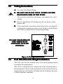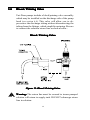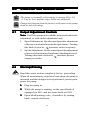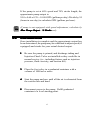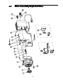
1
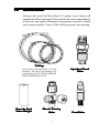
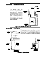
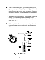
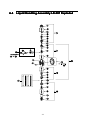
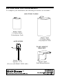
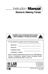
Instruction Manual Series U Electronic Metering Pumps For file reference, please record the following data: Model No: Serial No: Installation Date: Installation Location: When ordering replacement parts for your Uni-Dose Series U Pump or Accessory, please include the complete Model Number and Serial Number of your unit. Replaces same of Rev. C 5/97 1845. C 7/01 Contents 1.0 UNPACKING .......................................................... 3 2.0 PRE-INSTALLATION INSTRUCTIONS ................. 4 2.1 Precautions .................................................... 4 2.2 Chemical Compatibility Chart ......................... 6 3.0 INSTALLATION ...................................................... 7 3.1 Pump Location and Installation ...................... 7 3.2 Pump Mounting .............................................. 7 3.2.1 Flooded Suction ................................. 8 3.2.2 Suction Lift ......................................... 8 3.2.3 Injection into Well System ................ 10 3.3 Tubing Connections ..................................... 11 3.4 Foot Valve Tubing Installation ...................... 11 3.5 Injection Check Valve Installation ................. 13 3.6 Bleed/Priming Valve ..................................... 14 4.0 START-UP and ADJUSTMENT ........................... 15 4.1 Output Adjustment Controls ......................... 15 4.2 Start-Up / Priming ......................................... 15 4.3 Output Adjustment........................................ 16 5.0 CALIBRATION ...................................................... 17 6.0 MAINTENANCE ................................................... 19 6.1 Cleaning Liquid End (in place) ..................... 19 6.2 Cleaning Liquid End (disassembled) ............ 20 6.3 Changing Liquifram ...................................... 21 6.4 Liquid Handling Assembly Explod. View ...... 22 6.5 Liquid Handling Assembly Parts List ............ 23 6.6 Drive Assembly Parts List ............................ 24 6.7 Drive Assembly Explod. View ....................... 25 7.0 TROUBLESHOOTING ......................................... 26 1.0 UNP ACKING UNPA Along with your Uni-Dose Series U pump, your carton will contain the following items. Please notify the carrier immediately if there are any signs of damage to the pump or its parts. Notify your pump supplier if any of the following parts are missing. Tubing Your carton will contain three (3) rolls of tubing. The clear vinyl tubing is for connection to the SUCTION SIDE OF THE PUMP HEAD ONLY. Ceramic Foot Value Weight Bleed / Priming Valve 3 Injection Check Valve Foot Valve 2.0 PRE-INST ALLA TION INSTR UCTIONS PRE-INSTALLA ALLATION INSTRUCTIONS The following precautions should be taken when working with Uni-Dose metering pumps. Please read this section carefully prior to installation. 2.1 Precautions Protective Clothing ALWAYS wear protective clothing, face shield, safety glasses and gloves when working on or near your metering pump. Additional precautions should be taken depending on the solution being pumped. Refer to MSDS precautions from your solution supplier. Water Pre-Prime All Uni-Dose pumps are pre-primed with water when shipped from the factory. If your solution is not compatible with water, disassemble the Pump Head Assembly. Thoroughly dry the pump head, Uni-Valves, and Liquifram ™ (diaphragm). Reassemble head assembly tightening screws in a crisscross pattern. Refill the pump head with the solution to be pumped before priming the pump (this will aid in priming). Solution Compatibility Please refer to the Chemical Compatibility Chart on page 6 for the materials of construction of your pump. Should you have any further compatibility questions on your Uni-Dose Pump, please call the Liquid Metronics Customer Service Department. Tubing Connections Inlet and outlet tubing sizes must not be reduced. Make certain that all tubing is SECURELY ATTACHED to fittings prior to start-up. (See Section 3.3, Tubing Connections). ALWAYS use Liquid Metronics supplied tubing with your pump, as the tubing is specifically designed for maximum compatibility with the pump operation. It is recommended that all tubing be 4 shielded to prevent possible injury in case of rupture or accidental damage. Fittings And Machine Threads All fittings should be hand tightened to a maximum of 1/8 to 1 /4 turn after the fitting contacts the Uni-Valve. DO NOT OVERTIGHTEN FITTINGS. Overtightening or use of a pipe wrench can cause damage to the fittings, Uni-Valves, or pump head, causing the pump to LOSE PRIME OR NOT FUNCTION. DO NOT use Teflon tape or pipe dope to seal threads. Teflon Tape may only be used on the 1/2" NPT thread side of the Injection Check Valve before installing in a pipe line or tee. Plumbing Always adhere to your local plumbing codes and requirements. Be sure installation does not constitute a cross connection. Check local plumbing codes for guidelines. Liquid Metronics is not responsible for improper installations. Electrical Connections WARNING: to reduce the risk of electrical shock, the metering pump must be plugged into a grounded outlet with ratings conforming to the data on the pump control panel. The pump must be connected to a good ground. DO NOT USE ADAPTERS! All wiring must conform to local electrical codes. Figure 1: Electrical Connections 2.2 CHEMICAL COMPATIBILITY CHART Uni-Dose pumps are designed specifically for water conditioning. Other applications may require the use of chemicals not compatible with the materials of construction of the Uni-Dose. Materials of Construction Flexiprene - a thermoplastic elastomer vulcanizate Polypropylene Macroflex - an elastomeric copolymer U.V. Resistant Polyethylene Noryl PVC - polyvinyl chloride Chemical compatibility of the Uni-Dose with the following solutions is rated as good. For chemicals not listed, please contact your local representative or the factory. Alum Sodium Carbonate Calcium Hypochlorite Sodium Hydroxide Muriatic Acid (5% Hydrochloric Sodium Hypochlorite Acid) Sodium Hexametaphosphate Polyphosphates Sodium Phosphate Potassium Permanganate, 10% Sodium Thiosulfate Sodium Bicarbonate Vinegar DISCLAIMER OF WARRANTY AND LIABILITY Although the information set forth herein is presented in good faith and believed to be correct on the date of issuance, Liquid Metronics Division, Milton Roy Company makes no guarantee or representation as to the completeness or accuracy thereof, and disclaims all liability for any loss or damage resulting from use or reliance upon any information, recommendations or suggestions contained herein. LIQUID METRONICS DIVISION, MILTON ROY MAKES NO EXPRESS OR IMPLIED REPRESENTATIONS OR WARRANTIES AS TO THE FITNESS, MERCHANTABILITY, OR ANY OTHER MATTER WITH RESPECT TO THE INFORMATION CONTAINED HEREIN OR ANY PRODUCT OR SUBSTANCE REFERRED TO HEREIN, whether used alone or in combination with any other material. Nothing contained herein is to be construed as a recommendation to use any product in conflict with any patent. The data in all tables are based on samples tested and are not guaranteed for all samples or other applications. Write to us for our current sales specifications. 6 3.0 INST ALLA TION INSTALLA ALLATION 3.1 Pump Location and Installation Locate pump in an area convenient to solution tank and electrical supply. The pump should be accessible for routine maintenance, and should not be subjected to ambient temperatures above 110° F (43° C). If the pump will be exposed to direct sunlight, Liquid Metronics black, UV resistant tubing should be installed. 3.2 Pump Mounting Common Errors To avoid siphoning, do not install your Uni-Dose pump so that it pumps downhill or into the suction side of a pump. Your Uni-Dose metering pump must be mounted so that the suction and discharge valves are vertical. NEVER position pump head and fittings horizontally. Rubber Pad Placement To help reduce the noise of your Uni-Dose pump, we recommend installing the four (4) rubber foot pads as illustrated here: 3.37" (85.6 mm) .50"(12.7 mm) .37"(9.4 mm) 3.28 (83.3 mm) RUBBER PADS TYP.(4) PLACES Figure 2: Rubber Pad Replacement The pump can be mounted in one of two ways: 3.2.1 Flooded Suction (Ideal Installation) The pump is mounted at the base of the storage tank. This installation is the most trouble-free , and is recommended for very low outputs, solutions that gasify, and high viscosity solutions. Since the suction tubing is filled with solution, priming is accomplished quickly and the chance of losing prime is reduced. Figure 3: Flooded Suction Installation DO NOT immerse pump in solution 3.2.2 Suction Lift Maximum suction lift is 5 ft (1.5 m) for solutions having the specific gravity of water. For denser solutions, consult the factory. Suction Lift - Wall Bracket Mount The pump may be mounted using a Uni-Dose Wall-Mount Bracket Assembly (part no. 34643) directly above the solution tank. A pump mounted in this manner allows for easy changing of solution tanks or drums. Figure 4: Wall Bracket Mount Suction Lift - Tank Mount Injection Check Valve The pump may be mounted on a molded tank. Uni-Dose 15-gallon tanks (part no. 34054) and 35-gallon tanks (part no. 34055) are suitable for pump mounting. Uni-Dose Figure 5: Tank Mount 9 Suction Lift - Shelf Mount The pump may be mounted on a shelf (customer supplied) maintaining a suction lift of less than 5 ft (1.5 m). A Uni-Dose mounting kit (part number 10461) is available for securing the pump to a shelf. Figure 6: Shelf Mount 3.2.3 Injection into a Well Pump System If the Uni-Dose pump is to be used in conjunction with a well pump, the voltage of the Uni-Dose pump must match the voltage of the well pump. Install the injection check valve of your Uni-Dose pump into a pipe tee that is installed in the water line going to the pressure tank. The injection valve must be installed vertically (arrows pointing upward) on the bottom side of the water line to prevent backflow into the Uni-Dose pump's discharge line. Figure 7: Well Pump System 10 3.3 Tubing Connections A. Use only Uni-Dose tubing. B. DO NOT USE CLEAR VINYL TUBING ON THE DISCHARGE SIDE OF THE PUMP. The pressure created by the pump can rupture the vinyl tubing. C. Before installation, all tubing must be cut with a clean square end. D. Valve and head connections from the factory are capped or plugged to retain pre-prime water. Remove and discard these caps or plugs before connecting tubing. DO NOT USE PLIERS OR PIPE WRENCH ON COUPLING NUTS OR FITTINGS. Figure 8: Tubing Connections 3.4 Foot Valve/Ceramic Weight Installation The foot valve acts as a check valve to keep the pump primed in suction lift applications. The valve is designed to be submersed in the solution tank or drum and must sit in a vertical position at the bottom. Position approximately two 2 inches (50 mm) off the bottom if the tank or drum contains sediment. 11 The suction tubing straightener, when assembled, positions the foot valve and suction tubing in a vertical position. 1. Attach the foot valve to one end of the suction tubing (see Tubing Connections, section 3.3). 2. Assemble the suction tubing straightener by pushing together alternating yellow and black tubes. Adjust the length of the tubing straightener by pushing tubes further together so when placed over the suction tubing and sitting on the foot valve, approximately three (3) inches (75 mm) of tubing exits the tubing straightener on the side to be connected to the pump. 3. Place foot valve, tubing and suction tubing straightener into the solution tank. Check that the foot valve is vertical and approximately two (2) inches (50 mm) from the bottom of the tank or drum (see figure 9). Connect the other end of the tubing to the suction side of the pump head (bottom side). Proper Foot Valve Position Figure 9: Foot Valve Position 12 3.5 Injection Check Valve Installation The Injection Check Valve prevents backflow from a treated line. Connect the Injection Check Valve to your “DISCHARGE” (outlet) line. Any size NPTF fitting or pipe tee with a reducing bushing to 1/2" NPTF will accept the injection check valve. Use Teflon tape or pipe dope to seal the pipe threads only. When installing the Injection Check Valve, be sure to position it so that the valve enters the bottom of your pipe in a vertical position. Variations left and right within 80° are acceptable (see figure 10). After cutting an appropriate length of tubing, connect tubing to the injection check valve then back to the discharge side of the pump head (top side), making sure it does not crimp or come in contact with hot or sharp surfaces. Typical Injection Check Valve Installations ° Figure 10: Calibration 13 3.6 Bleed / Priming Valve Uni-Dose pumps include a bleed/priming valve assembly which may be installed on the discharge side of the pump head (see section 6.4). This valve will allow you to depressurize the discharge tubing without disconnecting the tubing from the fittings, which simplifies priming. Be sure to connect the solution return line as shown below: Bleed / Priming Valve Figure 11: Bleed / Priming Valve Warning: The return line must be secured to insure pumped solution will return to supply tank. DO NOT submerge return line in solution. 14 4.0 ST AR T-UP and ADJUSTMENT STAR ART The pump is normally self-priming if suction lift is 5 ft (1.5 m) or less, and the steps below are followed. Pumps are shipped from the factory with water in the pump head to aid in priming. 4.1 Output Adjustment Controls Note: Uni-Dose pumps are available with speed and stroke adjustment or with stroke adjustment only. 1. Speed Adjustment: Speed control provides adjustment of the percent of maximum strokes per minute. Turning this knob clockwise increases stroke frequency. 2. Stroke Adjustment: Stroke control provides adjustment of percent of maximum Liquifram (diaphragm) travel. Turning this knob clockwise increases percent output per stroke. 4.2 Start-Up/Priming Read this entire section completely before proceeding. When all precautionary steps have been taken, the pump is mounted, and the tubing is securely attached, you may now prime the pump. 1. Plug the pump in. 2. While the pump is running, set the speed knob (if equipped) at 80% and the stroke knob at 100%. 3. Open bleed/priming valve, if installed, by turning knob counter-clockwise. 15 4. The suction tubing should begin to fill with solution from the tank. 5. Once a solid stream of solution begins to exit the pump head or return tubing on the bleed/priming valve, close valve by turning knob clockwise. Disconnect the power cord. 6. The pump is now primed. 7. Proceed to output adjustment, Section 4.3. If the pump does not self-prime, remove the fitting or bleed/ priming valve on the discharge side of the pump head. Remove the Uni-Valve and pour water or solution into the port until the head is filled. Replace valve, then follow start up/priming steps. 4.3 Output Adjustment Once the pump has been primed, an appropriate output adjustment MUST be made, pump output should be calculated and adjustments made accordingly. Calculate the total output of the pump as follows: PUMP OUTPUT = MAX PUMP OUTPUT x %SPEED x %STROKE Example: U131-281 Use MAX Output (From dataplate on bottom center of pump control panel) = 24 GPD (gallons per day). 16 If the pump is set at 60% speed and 70% stroke length, the approximate pump output is: 24.0 x 0.60 x 0.70 = 10.08 GPD (gallons per day) Divide by 24 (hours in one day) to calculate GPH (gallons per hour). If pump is not equipped with speed adjustment, calculate by Max Pump Output x % Stroke only. 5.0 CALIBRA TION CALIBRATION Once installation is complete and the approximate output has been determined, the pump may be calibrated to adjust speed (if equipped) and stroke for your actual desired output. 1. Be sure the pump is primed, and discharge tubing and Injection Check Valve are installed as they would be in normal service (i.e., including factors such as injection pressure, fluid viscosity, and suction lift). 3. Place the foot valve in a graduated container with a volume of 1000 ml or more. 4. Start the pump and run until all the air is exhausted from the suction line and head. 5. Disconnect power to the pump. Refill graduated container to a level starting point. 17 6. Using a stopwatch or timer, start the pump and run for a measured amount of time (50 pump strokes minimum). The longer the time period, the more confident you can be of the results. Be sure to count the number of strokes during the calibration period when making comparisons. 7. Disconnect power to the pump. Note the time elapsed in relation to volume displaced in the graduate. Now, calculate the output in the time unit you choose (minutes, hours, days, etc.). 8. If the output is too low or too great, adjust speed and/or stroke, estimating required correction and repeat steps 1-7. Figure 12: Calibration 18 6.0 MAINTENANCE WARNING: ALWAYS wear protective clothing, face shield, safety glasses and gloves when performing any maintenance or replacement on your pump. Read this entire section before proceeding. WARNING: Extreme care should be taken to avoid spilling any solution from the tubing during these procedures. 6.1 Cleaning Liquid End (In-Place) Many water conditioning additives tend to be alkaline and scale forming. The following cleaning procedure may be used as often as necessary to ensure proper performance from your Uni-Dose pump: WARNING: DO NOT USE WATER TO FLUSH LIQUID END IF YOUR SOLUTION REACTS WITH WATER. 1. Turn off the metering pump. Carefully lift the foot valve out of the solution tank and place it in a container of water. Carefully depressurize and disconnect the discharge line from the injection check valve and place the end of the tubing in the an empty container.Turn the pump on to flush the head and tubing with clear water. The metering pump should be turned off when moving the foot valve from one container to another in order to prevent air from entering the pump head and possibly causing loss of prime. 2. Again turn off the metering pump. Lift the foot valve out of the container of water and place it in a container of cleaning solution. Turn on the metering pump and let it pump for approximately five (5) minutes or until any scale is dissolved. 3. Turn off the metering pump and transfer the foot valve to the container of water. Turn the pump on for long enough to flush the cleaning solution from the head and tubing. Turn pump off and return the foot valve to the solution tank. Reconnect the discharge tubing to the injection check valve. 19 4. Turn the pump on and let it pump at full output for approximately one minute, then return the output to the normal operating setting. 6.2 Cleaning Liquid End (Disassembled) If the solution being pumped forms deposits which cannot be cleaned in-place with the cleaning solution, the head and valves should be disassembled and cleaned, as frequently as experience indicates is necessary, as follows: WARNING: DO NOT USE WATER TO FLUSH LIQUID END IF YOUR SOLUTION REACTS WITH WATER. 1. Turn off the metering pump. Carefully depressurize and disconnect the discharge line from the injection check valve and place the end of the tubing in an empty container. Carefully lift the foot valve out of the solution tank and place it in a container of water. Turn the pump on to flush the head and tubing with clear water. Turn the pump off. Disconnect tubing from the suction and discharge valves at pump head. 2. Remove head by unscrewing four (4) pump head mounting screws. 3. Unscrew valve fittings and remove Uni-valves from fittings. Care should be taken when removing and cleaning valves to prevent damage to any sealing surface. DO NOT PINCH OR OTHERWISE DEFORM THE UNI-VALVE. DO NOT SCRATCH THE SURFACE OF THE LIQUIFRAM (diaphragm). 4. Soak and clean all Uni-valves with a suitable cleaning solution. 5. Inspect all valves and Liquifram (diaphragm) for imperfections. Replace as necessary. A spare parts kit SP-281 should be installed as often as necessary, at least once every twelve (12) months. 6. Assemble valves and head assembly exactly as shown in the exploded view. Tighten head screws in a crisscross pattern to 30 in-lbs. DO NOT OVERTIGHTEN. 20 If valves are dirty or not assembled exactly as shown in the exploded view, the pump will not operate. 6.3 Changing Liquifram (diaphragm) 1. Follow steps 1 & 2 of Cleaning Liquid End (Disassembled) in Section 6.2. 2. Adjust stroke length knob to 20% by rotating counterclockwise with the pump operating. Stop pump by unplugging cord set. 3. Grasp outer edge of Liquifram (diaphragm) with your fingers and rotate counterclockwise until removed. Before installing new Liquifram (diaphragm) be sure disk is properly installed in EPU assembly. 4. Install new Liquifram (diaphragm) by screwing it onto the threaded shaft until it bottoms. DO NOT SCRATCH THE SURFACE OF THE NEW LIQUIFRAM (diaphragm). 5. Set stroke adjustment knob to 100% before reinstalling pump head. Tighten four (4) head screws in a crisscross pattern to 30 in-lbs. DO NOT OVERTIGHTEN. 21 6.4 Liquid Handling Assembly LE-281 Exploded NOT INCLUDED IN or 22 6.5 Liquid Handling Assembly LE-281 Parts List KEY NO. PART NO. DESCRIPTION QUANTITY LE-281 1 2 3 4 5 6 7 8 9 10 12 13 14 15 16 30999 Injector Fitting, Noryl 1 30995* Uni-Valve Asm. 4 31623* Seal, Flexprene 1 30620 Valve Housing, PVC 4 26136 Clamp Ring 3 10299 Coupling Nut 4 27342-10 Tubing, .375" O.D. Black Polyethylene 1 31900 Head, 0.8 SI, PVC 1 10340 Screw, 10-24 x 3/4" S.S. 4 30981* Liquifram, 0.8 SI, Flexiprene 1 10469-06 Tubing, .375" O.D., Vinyl 1 31565* Spring, Hastelloy 1 30840 Foot Valve Seat 1 10123 Strainer, Polypropylene 1 31635 Injector Check/Back Pressure Valve Asm. 17 18 19 20 21 22 23 24 30986 Discharge Valve Assembly 30987 Suction Valve Assembly 30988 Foot Valve Assembly 30989 Head Assembly, LE-281 32293 Tubing Straightener 34744 Bleed / Priming Valve 25636-10 Tubing, .250" OD PE 25631 Coupling Nut 1 *Parts included in Spare Parts Kit SP-281 23 1 1 1 1 1 1 1 1 6.6 Drive Assembly Parts List Key No. Model Part No. scription Qty. 1 U 30827 Disk 2 U 10973 Seal 3 U011,U021, U031, U041 32370R EPU U121, U131, U141 All 230V Models 32371R EPU 4 U 10166 O-Ring 5 U 32367 Bumper 6 U 10422 Retaining Ring 7 U 25963 Washer, Nylon 8 U 30391 Washer, Rubber 9 U1 35744 Dual Pin 10 U0 36254 Pulser U1 36255 Pulser 11 U1 35743 Speed Shaft 12 U1 34497 O-Ring 13 U 25414 Spring 14 U1 30803 Gasket 15 U1 30709B Speed Knob 16 U 30306 Screw 17 U011, U021, U031, U041 10626 Varistor Assembly, 115V U121, U131, U141 U012, U022, U032, U042 31255 Varistor Assembly, 230V US U122, U132, U142 U013, U023, U033, U043 10627 Varistor Assembly, 230-250V U123, U133, U143 U015, U025, U035, U045 U125, U135, U145 U016, U026, U036, U046 U126, U136, U146 U017, U027, U037, U047 U127, U137, U147 18 U01, U03 31044 Stroke Dial U02, U12 36178 Stroke Dial U04, U14 33876 Stroke Dial 19 U 30295B Stroke Knob 20 U01 31066 Resistor Assembly U02 29797 Wire Assembly U 32357 Rubber Foot Pad (not shown) 24 De1 1 1 1 1 1 1 1 1 1 1 1 1 1 1 1 1 4 1 1 1 1 1 1 1 1 1 4 6.7 Drive Assembly Exploded View 25 7.0 TR OUBLESHOO TING TROUBLESHOO OUBLESHOOTING PROBLEM Pump Will Not Prime Pump Loses Prime POSSIBLE CAUSE 1. Pump not plugged in to live outlet. 2. Output knobs not set properly. 3. Foot Valve not in vertical position on bottom of tank. 4. Pump suction lift too high. 5. Suction tubing is curved or coiled in tank 6. Fittings are over-tightened. 7. Air trap in suction tubing. 8. Too much pressure at discharge. 1. Solution container ran dry 2. Foot Valve is not in a vertical position on the bottom of the tank. 3. Pump suction lift is too high. 4. Suction tubing is curved or coiled in tank. 5. Fittings are overtightened. 6. Air trap in suction valve tubing. 7. Air leak on suction side. 26 SOLUTION 1. Check outlet/plug in pump. 2. Always prime pump with speed at 80% (if equipped) and stroke at 100%. 3. Foot Valve must be vertical (See Foot Valve Installation, Section 3.4). 4. Maximum suction lift is 5 ft (1.5 m) Reduce suction lift or change to flooded suction. 5. Suction tubing must be vertical. Use tubing straightener supplied with pump. (See Section 3.4) 6. Do not overtighten fittings. This causes valves to distort and not seat properly which causes pump to leak back or lose prime. 7. Suction tubing should be as vertical as possible. AVOID FALSE FLOODED SUCTION! (See Section 3.2.1) 8. Check for closed valves or blockage in pressurized line. Eliminate problem and reprime pump if necessary (See priming Section 4.2). When pump is primed, reconnect discharge tubing. 1. Refill container with solution and reprime (See Section 4.2) 2. Foot Valve must be vertical (See Foot Valve Installation, Section 3.4). 3. Maximum suction lift is 5 ft (1.5 m). Reduce suction lift or change to flooded suction. 4. Suction tubing must be vertical. Use tubing straightener supplied with pump. (See Section 3.4) 5. Do not overtighten fittings. This causes valves to distort and not seat properly which causes pump to leak back or lose prime. 6. Suction tubing should be as vertical as possible. AVOID FALSE FLOODED SUCTION! (See Section 3.2.1) 7. Check for pinholes, cracks in tubing. Replace if necessary. 27 TR OUBLESHOO TING (continued) TROUBLESHOO OUBLESHOOTING PROBLEM Leakage at tubing Low Output or Failure to Pump Against Pressure Failure to Run Excessive Pump Output POSSIBLE CAUSE 1. Worn tubing ends. 2. Loose or cracked fitting. 3. Worn Uni-Valves. 4. Solution attacking Liquid Handling Assembly material. 1. Pump's maximum pressure rating is exceeded by injection pressure. 2. Worn Uni-Valves. 3. Ruptured Liquifram. 4. Tubing run on discharge may be too long. 5. Clogged foot valve strainer. 1. Pump not plugged in to live outlet. 2. EPU failure. 3. Pulser failure. 1. Siphoning. 2. Little or no pressure at injection point. 3. Excessive strokes per minute. 28 REMEDY 1. Cut about 1 in (25 mm) off tubing and then replace as before. 2. Replace fitting if cracked. Carefully hand tighten fittings. Do not use pipe wrench. Once fitting comes into contact with valve, tighten an additional 1/8 or 1/4 turn. 3. Replace Uni-Valves. (See Section 6.2) Spare Parts (SP-281) 4. Consult Uni-Dose Chemical Compatability Chart (Sec. 2.2) or factory. 1. Injection pressure cannot exceed pump's maximum pressure. See pump dataplate. 2. Worn Uni-Valves may need replacement. (See Section 6.2) Spare Parts (SP-281) 3. Replace Liquifram. (See Section 6.3). 4. Longer tubing runs may create frictional losses sufficient to reduce pump's pressure rating. Consult factory for more information. 5. Remove foot valve strainer , clean and reinstall. 1. Check outlet, plug in pump. 2. Disassemble pump and measure the resistance of the EPU across the EPU wires. Resistance reading should be 76-87 Ohms at 20°C /68o F (115VAC pump) or 307-353 Ohms at 20° C/ 68o F (230VAC pump). Also check EPU leads to ground. Consult supplier or factory. 3. The pulser should be replaced if EPU checks out OK. Consult supplier or factory. 1. Move injection point to a pressurized location. 2. Make sure spring loaded injection check valve is installed properly. 3. Replace pulser, resistor, or wire assembly. Consult factory. 29 OPTIONAL ACCESSORIES To complete your installation, the following accessories are available: SOLUTION TANKS Model 34054 15-Gallon White Polyethylene Tank AGITATORS Model 34055 35-Gallon White Polyethylene Tank WALL-MOUNT BRACKET Model 27591 Agitator, 115V (For use with Model 34055 tank) Model 34643 Wall-Mount Bracket