1
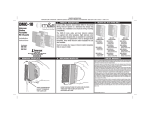
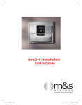
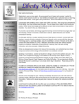
PRINTER’S INSTRUCTIONS: INSTR,INSTL,DMC-10 - LINEAR P/N: 227592 A
INK: BLACK - MATERIAL: 20 LB. MEAD BOND - SIZE: 5.500” X 8.500” - SCALE: 1-1 - FOLDING: ALBUM-FOLD - BINDING: SADDLE-STITCH
DMC-10
Structured Wire
Intercom System
Installation and
Operation Instructions
DMC-10H
Intercom Hub
DMC-10RS
Room Station
DMC-10PS
Patio Station
(760) 438-7000
USA & Canada (800) 421-1587 & (800) 392-0123
Toll Free FAX (800) 468-1340
www.linearcorp.com
www.mssystems.com
DMC-10DS
Door Station
Table of Contents
Introduction.............................................................................................. 1
Safety Information and Cautions ............................................................. 2
Explanation of Graphic Warning Symbols......................................... 2
General Wiring Cautions ................................................................... 2
Intercom Room Station Cautions ...................................................... 2
Important Safety Notes ..................................................................... 3
Component Features ............................................................................... 4
Installation ................................................................................................ 5
System Design ................................................................................... 5
Structured Wiring Enclosure ............................................................. 5
Hub Mounting ................................................................................... 5
Junction Box Installation ................................................................... 6
System Wiring.................................................................................... 6
Station Installation ............................................................................. 6
Hub Wiring ........................................................................................ 7
Optional Door Strike Installation ...................................................... 7
Optional Expansion Hub Installation................................................. 8
Optional Audio Input Wall Plate ....................................................... 8
Hub Options ...................................................................................... 9
Hub Power Supply Connection ......................................................... 9
Hub Status Indicators ........................................................................ 9
General Operation ................................................................................. 10
Intercom Features ........................................................................... 10
Volume Control ................................................................................ 10
Hands-free Reply ............................................................................. 10
Quick Listen ..................................................................................... 10
Door to Room and Door to Patio Communications ....................... 11
Room to Room and Room to Patio Communications ..................... 12
Patio to Room and Patio to Patio Communications ....................... 13
Constant Modes..................................................................................... 14
Privacy Mute Mode ......................................................................... 14
Do-not-disturb Mode ...................................................................... 14
Monitor Mode ................................................................................. 15
Listen Mode ..................................................................................... 15
Troubleshooting ..................................................................................... 16
System Setup and Option Log .............................................................. 17
Intercom Accessories & Kits .................................................................. 18
Limited Warranty.................................................................................... 19
FCC Notice ...................................................................................... 19
Introduction
Linear’s M&S Systems brand Model DMC-10 Structured Wiring Intercom
System offers several advanced features never before available in an
intercom system. Its distributed hub design provides easy installation and
structured wiring mounting compatibility necessary for modern residential
and light commercial applications.
The room, door, and patio stations showcase a new, contemporary design,
crafted to blend smoothly into the installation’s decor. Station faceplates
are available in a variety of colors to further customize each installation.
Room station keypads are illuminated with soft blue indicators while the
intercom is in use. The door and patio station keys are illuminated with
white lighting for easy nighttime operation.
The heart of the system is the Model DMC-10H Intercom Hub. The intercom
hub grid mounts in a structured wiring enclosure. Up to eight room, door,
and patio stations in any combination can be connected to the system hub
using up to 500 feet of standard Cat-5 cable for each station. For larger
installations, a second system hub can be added for expansion, providing a
total system capacity of up to 16 stations. The Model DMC-10AWP Audio
Input Wall Plate can be added to the system to connect an external audio
source for distribution throughout the intercom system.
The room, patio, and door stations mount inside standard 2-gang junction
boxes and are easy to install and wire. Each station and the system hub
contains color-coded Type 110 punch-down terminal blocks for fast and
reliable connection to Cat-5 cable. A 12-volt switching power supply is
included with each intercom hub.
CAT-5
CAT-5
LISTEN
DOOR
VOL
TALK
MUTE
DMC-10DS
DOOR STATION
DMC-10H
INTERCOM HUB
OPENHOUSE
STRUCTURED
WIRING
CABINET
CAT-5
DOOR
VOL
MUTE
CAT-5
DMC-10PS
PATIO STATION
DOOR
VOL
TALK
MUTE
POWER
SUPPLY
SIGNAL
OVERLOAD
DOOR
SIGNAL
LEVEL ADJ.
MUTE
OUTPUT
TALK
CAT-5
LISTEN
TALK
LISTEN
VOL
DMC-10RS
ROOM
STATIONS
CAT-5
MUTE
AUDIO
LEFT
INPUT
RIGHT
DMC-10AWP
DMC-10AWP
AUDIO INPUT
WALL PLATE
Figure 1. Typical DMC-10 Installation
1
Safety Information and Cautions
Explanation of Graphic Warning Symbols
This symbol is intended to alert the user to the presence of un-insulated
“dangerous voltage” within the product’s enclosure that may be of
sufficient magnitude to constitute a risk of electric shock.
This symbol is intended to alert the user to the presence of important
operating and maintenance (servicing) instructions in the literature
accompanying the device.
WARNING! To prevent fire or shock hazard, do not expose this device
to rain, water, or wet locations.
CAUTION
RISK OF ELECTRIC SHOCK
DO NOT OPEN
CAUTION: TO REDUCE THE RISK OF ELECTRIC SHOCK
DO NOT REMOVE COVER (OR BACK)
NO USER-SERVICEABLE PARTS INSIDE
REFER SERVICE TO QUALIFIED PERSONNEL
General Wiring Cautions
• DO NOT USE EXCESSIVE FORCE ON PUNCH-DOWN TERMINALS! IF
USING AN IMPACT TYPE 110 PUNCH-DOWN TOOL, SET THE FORCE
ADJUSTMENT TO “LOW” BEFORE TERMINATING CAT-5 CABLES.
• The 120 VAC line to the structured wiring enclosure’s junction
box must be run by a licensed electrician.
• Individual CAT-5 cable runs from the hub to any station or
audio input wall plate should not exceed 500 feet.
• Label all cables for identification at the intercom hub.
• DO NOT SPLICE CABLES! Splices are unreliable and defeat
the signal isolation properties of the cable.
• DO NOT STAPLE CABLES! Staples cause shorts.
• DO NOT RUN 120 VAC ELECTRICAL WIRES INSIDE INTERCOM STATION JUNCTION
BOXES. If you encounter 120 VAC wires running through station junction boxes,
you must have a qualified electrician rerun those wires around the junction box.
• KEEP CABLES AT LEAST 18 INCHES FROM FLORESCENT LIGHT FIXTURES, DIMMER
CONTROLS, AND ALL OTHER WIRING. This includes AC wiring, security cable, cordless
phone units, and other control wires. These can cause a “hum” or “buzzing” sound.
• Keep all cables away from objects such as heating and air conditioning ducts, metal
construction plates, and anything else with sharp edges that can damage cables.
Intercom Room Station Cautions
• DO NOT install room stations in saunas. They will not withstand the extreme heat or moisture.
• DO NOT install room stations within 10 feet of other room stations, in the same stud
cavity as other room stations, or facing each other. This will cause acoustic feedback.
2
Safety Information and Cautions (Continued)
Important Safety Notes
POWER SOURCE This unit should only be connected to a
110-120 VAC power source as marked on the unit.
GROUNDING OR POLARIZATION Do not defeat the safety purpose of the polarized
or grounding-type plug. A polarized plug has two blades with one wider than the
other. A grounding type plug has two blades and a third grounding prong. The wide
blade or the third prong are provided for your safety. If the provided plug does not fit
into your outlet, consult an electrician for replacement of the obsolete outlet.
NON-USE PERIODS Always turn the unit off and unplug when it is
not being used or left unattended for long periods of time.
OBJECT AND LIQUID ENTRY Never push objects of any kind into the unit through
the cabinet slots as they may touch dangerous voltage points or short out parts that
could result in a fire or electric shock. Never spill liquid of any kind on the unit.
CLEANING Unplug the unit from the wall outlet before cleaning or polishing
it. Do not use liquid cleaners, aerosol cleaners, gasoline or other flammable
fluid. Clean the exterior of the unit with a slightly damp cloth.
WATER AND MOISTURE Do not use power line operated units near water - for example, near a
bathtub, washbowl, kitchen sink, or laundry tub, in a wet basement, or near a swimming pool.
VENTILATION The appliance should be situated so that its location or position does not interfere
with its proper ventilation. For example, the unit should not be situated on a bed, sofa, rug or
placed in a built-in installation that may block the flow of air through the ventilation openings.
POWER CORD PROTECTION Power supply cords should be routed so that they are not likely
to be walked on or pinched by items placed upon or against them paying particular attention to
cords at plugs, convenience receptacles, and the point where they exit from the appliance.
READ INSTRUCTIONS All the safety and operating instructions
should be read before the product is operated.
RETAIN INSTRUCTIONS The safety and operating instructions
should be retained for future reference.
HEED WARNINGS All warnings on the product and in the
operating instructions should be adhered to.
FOLLOW INSTRUCTIONS All operating and use instructions should be followed.
ATTACHMENTS Do not use attachments not recommended by the
product manufacturer as they may cause hazards.
ACCESSORIES Do not place this product on an unstable cart, stand, tripod, bracket, or table.
The product may fall, causing serious injury to a child or adult, and serious damage to the
product. Use only with a cart, stand, tripod, bracket or table recommended by the manufacturer,
or sold with the product. Any mounting of the product should follow the manufacturer’s
instructions, and should use a mounting accessory recommended by the manufacturer.
OVERLOADING Do not overload wall outlets, extension cords, or integral
convenience receptacles as this can result in a risk of fire or electric shock.
REPLACEMENT PARTS When replacement parts are required, be sure the service technician
has used replacement parts specified by the manufacturer or have the same characteristics as
the original part. Unauthorized substitutions may result in fire, electric shock, or other hazards.
SAFETY CHECK Upon completion of any service or repairs to this product, ask the service
technician to perform safety checks to determine that the product is in proper operating condition.
WALL OR CEILING MOUNTING The product should be mounted to a
wall or ceiling only as recommended by the manufacturer.
HEAT The product should be situated away from heat sources such as radiators, heat
registers, stoves, or other products (including amplifiers) that produce heat.
3
Component Features
POWER
CONNECTOR
MUTE ENABLE
SWITCHES
DOOR RELEASE
ENABLE SWITCHES
DOOR RELEASE
CONNECTOR
EXPANSION HUB
STATUS INDICATOR
EXPANSION HUB
CONNECTOR
STATION STATUS
INDICATORS (8)
STATION
CONNECTORS (8)
DMC-10H
INTERCOM HUB
UNLOCK
BUTTON
MICROPHONE
LISTEN
BUTTON
TALK
BUTTON
DMC-10RS
ROOM STATION
TALK
BUTTON
MICROPHONE
DOOR
TALK
BUTTON
DOOR
TALK
BUTTON
VOLUME
CONTROL
VOLUME
CONTROL
MUTE
BUTTON
MUTE
BUTTON
DMC-10PS
PATIO STATION
MICROPHONE
SIGNAL
OVERLOAD
INDICATOR
DOOR
CHIME
BUTTON
SIGNAL
OVERLOAD
SIGNAL
LEVEL ADJ.
SIGNAL LEVEL
ADJUSTMENT
MUTE
OUTPUT
AUDIO
INPUT
JACKS
AUDIO
LEFT
INPUT
RIGHT
MUTE
OUTPUT
DMC-10AWP
DMC-10DS
DOOR STATION
DMC-10AWP
AUDIO INPUT WALLPLATE
Figure 2. Station and Hub Features
4
Installation
System Design
Evaluate the installation to determine locations for mounting the
intercom components. The intercom hub mounts in a new or existing
structured wiring enclosure. The DMC-10RS room stations can be
located in any rooms that require communications. DMC-10PS patio
stations are weather resistant and designed to be mounted in protected
areas outdoors. DMC-10DS door stations are also weather resistant and
typically mounted next to the primary visitor entrance and any other
auxiliary entrances. Up to eight stations of any type can be connected
to one DMC-10H hub. An additional DMC-10H hub can be connected to
the primary hub for expansion, increasing the system capacity to sixteen
stations total.
Structured Wiring Enclosure
Linear’s OpenHouse brand Model
H312KIT 12-inch high structured
wiring enclosure is recommended for
mounting the DMC-10H hub. Other
OpenHouse enclosures can also be
used to mount the hub. Enclosures
mount recessed, between wall studs,
or can be surface mounted. Be sure
the enclosure is in a location where
117 VAC power can be routed to the
enclosure by a licensed electrical
contractor for connection to an
outlet in the enclosure.
Hub Mounting
The hub locks into the mounting grid
of the structured wiring enclosure
the same as other structured wiring
modules (see Figure 4). Hook the
mounting tabs into the grid, swing
the hub into place, and push the
locking button to finish the hub
mounting.
MOUNTING
GRID
AC OUTLET
Figure 3. OpenHouse Model H312KIT
Structured Wiring Enclosure
1 HOOK MODULE INTO GRID
2 SWING MODULE INTO PLACE
3
PUSH BUTTON
TO LOCK MODULE
INTO GRID
4
MODULE INSTALLED
READY FOR HOOK-UP
Figure 4. Hub Mounting in the Enclosure
5
Installation (Continued)
Junction Box Installation
Each intercom station mounts inside
a standard 2-gang J-box. Mount the
J-boxes flush with the drywall at
locations and heights convenient
for the installation.
MOUNT 2-GANG J-BOX
AT EACH STATION LOCATION
System Wiring
Route Cat-5 or Cat-5e cable from
each station’s J-box to the structured
wiring enclosure where the hub will
be mounted. Drill through studs and
headers to accommodate cabling.
Secure the cables with zip-tie straps
(be careful not to puncture or pinch
cables with staples). Route all cables
18” away from AC wiring and
lamp dimmers. Route the cables
from the stations into the enclosure
through the wiring knockouts. Label
each cable’s station location at the
enclosure end.
Station Installation
Remove the faceplate from the
station by twisting a screwdriver in
the slot under the lower left corner
of the faceplate. Use a Type 110
punch-down tool (if using an impact
tool, set the tool to “low” force!)
to connect the Cat-5 cable’s eight
wires to the color coded connector
on the back of each station. After
wiring, install the station into the
J-box, secure it with the four screws,
and replace the faceplate. Note:
Alternate color station faceplates
are available (see Page 18).
6
MOUNT J-BOX
FLUSH TO THE
WALL SURFACE
Figure 5. Junction Box Installation
MAXIMUM WIRE RUN:
500 FEET OF CAT-5 CABLE
FROM EACH STATION
TO THE ENCLOSURE
STATION
J-BOX
CAT-5 CABLES
FROM STATIONS
CAT-5 CABLE
TO ENCLOSURE
STRUCTURED
WIRING
ENCLOSURE
LABEL STATION
LOCATIONS
ON CABLES
Figure 6. Pre-wiring Cat-5 Cable
ZIP-TIE CABLE
BLUE STRIPE
BLUE
ORANGE STRIPE
ORANGE
GREEN STRIPE
GREEN
BROWN STRIPE
BROWN
1 TWIST SCREWDRIVER
IN SLOT TO REMOVE
2 USE TYPE 110 PUNCH DOWN
FACEPLATE
TOOL TO CONNECT CABLE
3 INSTALL STATION IN J-BOX
DO NOT OVER-TIGHTEN SCREWS!
4 SNAP FACEPLATE
ONTO STATION
Figure 7. Station Installation
Installation (Continued)
Hub Wiring
Use a Type 110 punch-down tool (if
using an impact tool, set the tool
to “low” force!) to connect the
Cat-5 cable from each station to the
color coded connectors on the hub.
Wire the door station(s) first. The
hub’s station location number
determines the sound of the door
station’s chime.
Hub station 1, 2, or 3 = ding-dong
Hub station 4, 5, or 6 = dong-dong
Hub station 7 or 8 = dong-ding
CHIME 1
"DING-DONG"
CHIME 3
"DONG-DING"
CHIME 2
"DONG-DONG"
DOOR STATION LOCATION NUMBER
DETERMINES THE CHIME SOUND
Figure 8. Door Station Chime Selection
Wire the remaining stations to the
hub connectors. To document the
installation, note the station type
and locations in the log on Page 17.
USE A TYPE 110
PUNCH-DOWN TOOL
TO TERMINATE CAT-5
CABLES FROM
STATIONS
BLUE STRIPE
BLUE
ORANGE STRIPE
ORANGE
GREEN STRIPE
GREEN
BROWN STRIPE
BROWN
CONNECT
CAT-5 CABLE
WIRES IN
THIS ORDER
Figure 9. Hub Wiring
Optional Door Strike Installation
The intercom hub features a normally
open door release relay that can
switch up to 3 amps @ 30 volts.
The relay can be used to activate
a Model DRW electric door strike.
The relay is triggered by pressing
button on any room station.
the
Note: The unlock feature can be
disabled on any room station using
the option switches on the hub.
24 VAC
DOOR STRIKE
POWER SUPPLY
DMC-10H DOOR
RELEASE RELAY
3 AMP LOAD MAXIMUM !
M&S SYSTEMS
MODEL DRW
24 VAC ELECTRIC
DOOR STRIKE
DO NOT POWER
DOOR STRIKE FROM
INTERCOM POWER
SUPPLY !
CAUTION !
USE ONLY ONE
DOOR STRIKE
PER SYSTEM
Figure 10. Electric Door Strike Wiring
7
Installation (Continued)
Optional Expansion Hub Installation
To increase the system’s capacity,
a second hub can be connected to
the primary hub. The hubs connect
to each other with up to 150 feet of
Cat-5 cable. Each hub requires its
own power supply.
Mount the second hub in the
enclosure (or in another enclosure).
Connect the primary hub to the
second hub using the connectors
labeled EXPANSION. Note: Match
the wire colors to the connector
on the 1st hub, flip the wire pair
order on the second hub (see
Figure 11).
BLUE STRIPE
BLUE
ORANGE STRIPE
ORANGE
GREEN STRIPE
GREEN
BROWN STRIPE
BROWN
PRIMARY HUB
UP TO 150 FEET
OF CAT-5 CABLE
NOTE: WIRE PAIRS CHANGE
ORDER ON SECOND HUB !
EXPANSION HUB
BROWN STRIPE
BROWN
GREEN STRIPE
GREEN
ORANGE STRIPE
ORANGE
BLUE STRIPE
BLUE
Figure 11. Expansion Hub Wiring
Connect up to eight additional
stations to the expansion hub.
Wiring is the same as the primary
hub.
Optional Audio Input Wall Plate
An external audio source can be
connected to the system using the
Model DMC-10AWP wall plate. The
wall plate connects to one of the
hub’s station connectors in place of
a station. Room and patio stations
set to Listen Mode can play the
audio source. The audio source will
be automatically muted when the
intercom is in use.
MODEL DMC-10H
CONNECT TO ANY
AVAILABLE STATION
LOCATION ON HUB
UP TO 500 FEET
OF CAT-5 CABLE
SIGNAL
OVERLOAD
INDICATOR
SIGNAL
OVERLOAD
SIGNAL
LEVEL ADJ.
MUTE
OUTPUT
The audio input wall plate also
features an input level control and
a mute output. The mute output
is a relay contact closure that can
be used to silence an independent
music system when the intercom is
in use.
8
SIGNAL
LEVEL
ADJUSTMENT
AUDIO
MODEL
DMC-10AWP
LEFT
INPUT
MUTE
OUTPUT
RIGHT
DMC-10AWP
AUDIO INPUT
FROM SOURCE
Figure 12. Audio Wall Plate Wiring
Installation (Continued)
Hub Options
The intercom hub has two banks of
dipswitches. One bank enables or
disables each door station’s door
button. The other bank
release
enables or disables each door or
patio station’s privacy mute and donot-disturb feature.
Select the options appropriate for
the installation. The numbers on the
dipswitches correspond to the hub’s
station numbers. Mark the switch
settings in the log on Page 17.
Hub Power Supply Connection
The switching power supply module
included with each hub powers the
hub and all stations connected to
it. If an expansion hub is used, it
requires its own power supply.
SWITCH NUMBERS 1-8 MATCH
THE STATION NUMBERS 1-8
MUTE SWITCH
STATIONS WITH SWITCHES
THAT ARE "ON" WILL BE
ABLE TO USE PRIVACY
MUTE MODE
O
N
F
F
O
N
F
F
DOOR RELEASE SWITCH
STATIONS WITH SWITCHES
THAT ARE "ON" WILL BE
ABLE TO ACTIVATE THE
DOOR RELEASE RELAY
Figure 13. Hub Option Switches
PLUG POWER SUPPLY OUTPUT INTO
THE INTERCOM HUB'S POWER CONNECTOR
Place the power supply in the
enclosure with the hub. Insert the
power supply output plug into the
hub’s POWER jack. Insert the power
supply’s power cord into the 117 VAC
outlet installed in the enclosure.
Hub Status Indicators
When the hub powers up, a
diagnostic check is run for all the
stations connected. On the hub, the
green indicator above the station’s
connector will light and stay lit for
all stations that pass the diagnostic
check (also for the optional expansion
hub). If any hub indicators do not
light, check the wiring associated
with that connector.
The diagnostic check only occurs
when power is applied to the hub.
To perform the diagnostic check at
any time, cycle the hub power off
then on again.
POWER
SUPPLY
PLUG POWER SUPPLY INPUT
INTO 117 VAC OUTLET
BUNDLE EXCESS
POWER SUPPLY
CABLES
Figure 14. Power Supply Connections
INTERCOM HUB
STATION STATUS
INDICATORS
EACH TIME POWER
IS APPLIED TO THE
HUB, THE HUB CHECKS
THE STATUS OF ALL
CONNECTED STATIONS
2
THE STATION STATUS
INDICATORS WILL LIGHT
FOR EACH STATION
(AND EXPANSION HUB)
THAT CHECKS OK
Figure 15. Hub Status Indicators
9
General Operation
Intercom Features
Each room and patio station can be used for communication with other
room, patio, or door stations. Also, room and patio stations feature four
special constant modes for room monitoring and privacy.
If the optional audio input wall plate is installed, room and patio stations
can be set to play to the audio source connected to the wall plate.
Volume Control
Volume at each station can be set
with its VOL button. Each momentary
VOL↑ press increases, or VOL↓ press
decreases, the station’s volume.
Pressing and holding the VOL↓
button for one second will silence
the station’s speaker. When the
station’s volume is set all the way
down, the VOL button will remain
dimly lit. Pressing and holding the
VOL↑ button for one second returns
the volume to its previous level.
Hands-free Reply
Room stations will automatically
listen to all other room and patio
stations for 25 seconds after the
room station’s TALK button is
released (except for stations in
privacy mute or Do-not-disturb
Mode). This allows for a “handsfree” reply from the person being
called. This also applies when
communicating with door stations
using the room or patio station’s
DOOR button.
Quick Listen
To momentarily listen to all of the
room and patio stations without
making a call, press and hold the
room station’s LISTEN button. This
mode WILL NOT listen to stations
in Privacy Mute Mode or Do-notdisturb Mode.
THE VOLUME CONTROL
HAS EIGHT LEVELS
VOL
TALK
MUTE
PRESS VOL
TO
INCREASE THE
STATION'S VOLUME
PRESS VOL
TO
DECREASE THE
STATION'S VOLUME
TO TURN SPEAKER OFF
PRESS AND HOLD VOL
FOR ONE SECOND TO
SILENCE THE STATION'S
SPEAKER
TO TURN SPEAKER ON
PRESS AND HOLD VOL
FOR ONE SECOND TO
RETURN TO STATION'S
LAST VOLUME SETTING
Figure 16. Volume Control
AFTER RELEASING THE TALK
BUTTON, THE ROOM STATION
WILL LISTEN TO ALL OTHER
ROOM AND PATIO STATIONS
FOR 25 SECONDS
OTHER STATIONS SET TO PRIVACY MUTE MODE OR
DO-NOT-DISTURB MODE WILL NOT BE MONITORED
Figure 17. Hands-free Reply
PRESS AND HOLD THE
LISTEN BUTTON TO MONITOR
ALL OTHER ROOM AND PATIO
STATIONS WITHOUT MAKING
A CALL
RELEASE THE LISTEN BUTTON
TO STOP MONITORING
OTHER STATIONS SET TO PRIVACY MUTE MODE OR
DO-NOT-DISTURB MODE WILL NOT BE MONITORED
Figure 18. Quick Listen
10
General Operation (Continued)
Door to Room and Door to Patio Communications
When visitors arrive, they push a door station button to announce their
arrival. Pressing the door station’s button sounds a chime on all stations
(unless the station is set to Do-not-disturb Mode).
Door Button
To communicate with the visitor at
the door station, press and hold
the room or patio station’s DOOR
button while speaking. Release the
DOOR button to listen to the visitor
for 25 seconds. Press and hold the
DOOR button again at any time to
continue talking to the visitor, each
time the DOOR button is released,
the listening time will be extended
another 25 seconds.
PRESS AND HOLD THE
DOOR BUTTON TO TALK
TO A VISITOR AT
THE DOOR STATION
RELEASE THE DOOR BUTTON TO
LISTEN TO THE VISITOR AT THE DOOR STATION
(LISTEN LASTS FOR 25 SECONDS)
Figure 19. Door Button
Unlock Button
If a door release has been installed,
button on a room
pressing the
station will activate the door release
for four seconds (if the door release
feature is enabled for the station on
the hub). The door release will stay
activated as long as the
button is
held down.
PRESS THE UNLOCK BUTTON
TO ACTIVATE THE DOOR
RELEASE FOR FOUR SECONDS
THE DOOR RELEASE WILL STAY ACTIVATED
FOR AS LONG AS THE UNLOCK BUTTON IS PRESSED
Figure 20. Unlock Button
Mute Button
The communication session can be
canceled at any time before the 25
second listening period expires by
pressing the MUTE button.
PRESSING THE MUTE BUTTON
ANYTIME DURING LISTENING
STOPS THE INTERCOM
SESSION
Figure 21. Mute Button
11
General Operation (Continued)
Room to Room and Room to Patio Communications
A typical use for the system is to communicate between room stations
throughout the installation and to patio stations.
Talk Button
To communicate with other people
at room or patio stations, press and
hold the room station’s TALK button
while speaking. Release the TALK
button to listen to all other room
and patio stations for 25 seconds
(except stations in Privacy Mute or
Do-not-disturb Modes). Press and
hold the TALK button again at any
time to continue talking, after the
TALK button is released, the listening
time will be extended another 25
seconds.
Hands-free Reply Direction
Either person can change the
direction
of
the
hands-free
conversation by pressing and
holding their TALK button while
speaking. After any TALK button is
released the other person will be
able to reply hands-free during the
25 second listening period (except
after a TALK button has been pressed
on a patio station).
PRESS AND HOLD THE
TALK BUTTON WHILE SPEAKING
TO THE OTHER STATIONS
RELEASE THE TALK BUTTON
TO LISTEN TO THE OTHER
STATIONS
Figure 22. Room Station Talk Button
AFTER RELEASING THE TALK
BUTTON, THE ROOM STATION
WILL LISTEN TO ALL OTHER
ROOM AND PATIO STATIONS
FOR 25 SECONDS
OTHER STATIONS SET TO PRIVACY MUTE MODE OR
DO-NOT-DISTURB MODE WILL NOT BE MONITORED
Figure 23. Hands-free Reply
Mute Button
To cancel the communication session
at any time before the 25 second
listening period expires, press the
MUTE button.
PRESSING THE MUTE BUTTON
ANYTIME DURING LISTENING
STOPS THE INTERCOM
SESSION
Figure 24. Room Station Mute Button
12
General Operation (Continued)
Patio to Room and Patio to Patio Communications
A person at the patio station can make a call to the room stations, or
another patio station. For security and privacy, the patio station will
not trigger hands-free reply from room or other patio stations.
Talk Button
To communicate with people inside,
press and hold the patio station’s
TALK button while speaking. Release
the TALK button and wait for a reply
from the inside stations. Press and
hold the TALK button again at any
time to repeat the call if it was
unanswered.
To ensure privacy, releasing the
patio station’s TALK button WILL
NOT cause automatic listening to
the room stations for 25 seconds.
The person at a room station (or
another patio station) must always
press TALK to respond to a patio
station. When the room station’s
TALK button is released, the room
station will listen to the patio station
and all other stations for 25 seconds
(except stations in Privacy Mute or
Do-not-disturb Mode). Each time
the room station’s TALK button is
released, the listening time will be
extended another 25 seconds.
Mute Button
To cancel the communication session
at any time before the 25 second
listening period expires, press the
MUTE button.
PRESS AND HOLD THE
TALK BUTTON WHILE SPEAKING
TO THE OTHER STATIONS
RELEASE THE TALK BUTTON
AND LISTEN FOR ANOTHER
STATION TO RETURN THE
CALL
Figure 25. Patio Station Talk Button
PRESSING THE MUTE BUTTON
ANYTIME DURING LISTENING
STOPS THE INTERCOM
SESSION
NOTE: To prevent neighbors from
hearing private inside intercom
conversations, reduce the patio
station’s volume when it is not in
use.
Figure 26. Patio Station Mute Button
13
Constant Modes
Four special constant modes are available for room stations and patio
stations. Each room and patio station can be set to one of the four
modes. Constant modes remain in effect, even after the intercom is
used for other functions. The constant modes can be used to (1) prevent
monitoring from other stations; (2) prevent monitoring and calling from
other stations; (3) monitor sounds in other rooms or audio from an
external source; or (4) select specific room stations or patio stations for
constant monitoring.
Privacy Mute Mode
For privacy, room and patio stations
can be set to prevent monitoring
from other stations (if the mute
feature is enabled for the station on
the hub).
To enter or exit Privacy Mute Mode,
momentarily press the station’s
MUTE button. In Privacy Mute Mode
the station’s MUTE button lights.
The station can still perform regular
intercom communications while in
Privacy Mute Mode.
Do-not-disturb Mode
For privacy and silence, room and
patio stations can be set to prevent
monitoring and calling from other
stations (if the mute feature is
enabled for the station on the hub).
To select Do-not-disturb Mode, press
and hold the station’s MUTE button
for two seconds. In Do-not-disturb
Mode the station’s MUTE and VOL
buttons light. To exit Do-not-disturb
Mode, press the MUTE button.
The station can still perform regular
intercom communications if the
call is made from the station in
Do-not-Disturb Mode.
14
TO SELECT PRIVACY MUTE
MODE FOR THE STATION,
PRESS THE MUTE BUTTON
WHILE THE STATION IS IDLE
WHEN THE STATION IS IN
PRIVACY MUTE MODE, THE
MUTE BUTTON WILL STAY LIT
OTHER STATIONS WILL
NOT BE ABLE TO MONITOR
THIS STATION WHEN IT IS
IN PRIVACY MUTE MODE
TO EXIT PRIVACY MUTE
MODE, PRESS THE MUTE
BUTTON AGAIN
Figure 27. Privacy Mute Mode
TO SELECT DO-NOT-DISTURB
MODE FOR THE STATION,
PRESS THE MUTE BUTTON
FOR TWO SECONDS
WHEN THE STATION IS IN
DO-NOT-DISTURB MODE, THE
MUTE AND VOL BUTTONS
WILL STAY LIT
OTHER STATIONS WILL
NOT BE ABLE TO MONITOR
OR CALL THIS STATION WHEN
IT IS IN DO-NOT-DISTURB MODE
TO EXIT DO-NOT-DISTURB
MODE, PRESS THE MUTE
BUTTON AGAIN
Figure 28. Do-not-disturb Mode
Constant Modes (Continued)
Monitor Mode
Monitor Mode is typically used for
monitoring a baby or other sounds
in a room. When a room or patio
station is set to Monitor Mode, the
station’s microphone is always on.
Set other stations to Listen Mode
(see below) to hear sounds from any
station(s) set to Monitor Mode.
To enter or exit Monitor Mode,
press the station’s MUTE and TALK
buttons together. In Monitor Mode,
the station’s TALK button lights.
The station can still perform regular
intercom communications while in
Monitor Mode.
Listen Mode
When a room or patio station is
set to Listen Mode, the station’s
speaker is always on. Set a station
to Listen Mode to hear all stations
set to Monitor Mode.
Also, if the optional audio input
wall plate has been installed, set a
station to Listen Mode to play the
audio source connected to the wall
plate.
To enter or exit Listen Mode, press
the station’s MUTE and LISTEN
buttons together. In Listen Mode,
the station’s LISTEN button lights.
The station can still perform regular
intercom communications while in
Listen Mode.
TO SELECT MONITOR MODE
MODE FOR THE STATION,
PRESS THE TALK AND MUTE
BUTTONS TOGETHER
WHEN THE STATION IS IN
MONITOR MODE, THE
TALK BUTTON WILL
STAY LIT
SET OTHER STATIONS
TO LISTEN MODE TO
HEAR SOUNDS FROM
STATIONS IN MONITOR
MODE
TO EXIT MONITOR MODE,
PRESS THE TALK AND MUTE
BUTTONS TOGETHER
Figure 30. Monitor Mode
NOTE: For silent, uninterrupted
monitoring at the room station in
Monitor Mode, set the station’s
volume all the way down.
TO SELECT LISTEN
MODE FOR THE STATION,
PRESS THE MUTE AND
LISTEN BUTTONS TOGETHER
WHEN THE STATION IS IN
LISTEN MODE, THE LISTEN
BUTTON WILL STAY LIT
SET OTHER STATIONS TO
MONITOR MODE TO HEAR
THEM USING LISTEN MODE
LISTEN MODE CAN ALSO BE
USED TO PLAY AUDIO FROM
THE AUDIO WALL PLATE
TO EXIT LISTEN MODE,
PRESS THE MUTE AND LISTEN
BUTTONS TOGETHER
Figure 29. Listen Mode
NOTE: On Patio stations, press
MUTE and VOL↑ to enter or exit
Listen Mode.
15
Troubleshooting
SYMPTOM
CAUSE
SOLUTION
No hub status
indicators lit
No power to hub
Check power
supply input &
output voltage
Hub station status
indicator not lit on
an installed station
Wiring error
Check Cat-5
wiring, redo wiring
if necessary
Expansion hub
status indicator not
lit (with expansion
hub installed)
Wiring error or
no power to
expansion hub
Check Cat-5 wiring to
expansion hub, redo
wiring if necessary,
check expansion
hub power supply
Hum or buzz in audio
Check for station
Cat-5 wiring near
Electrical interference
AC power wires or
near lamp dimmers
Door station sounds
wrong chime
Door station wired to
wrong hub connector
Wire door station
to a different hub
connector for the
correct chime
Stations came out
of constant modes
Power interruption
at hub
Reset stations into
constant modes
Station will not
go into Privacy
Mute Mode
Set hub mute
Hub mute dipswitch
dipswitch for
for station set to OFF
station to ON
Station will not go
into Do-not-disturb
Mode
Set hub mute
Hub mute dipswitch
dipswitch for
for station set to OFF
station to ON
Station will not
activate door release
Hub door release
dipswitch for
station set to OFF
Set hub door
release dipswitch
for station to ON
Cannot monitor
a station in
Listen Mode
Station to monitor
set to Privacy
Mute Mode or
Do-not-disturb Mode
Take station
out of Privacy
Mute Mode or
Do-not-disturb Mode
by pressing MUTE
Low or no intercom
volume
Station’s volume
control set low or off
Reset station’s
volume control
16
System Setup and Option Log
STATION
NUMBER
TYPE
1
❑ ROOM STATION
❑ PATIO STATION
❑ DOOR STATION
MUTE ❑ OFF ❑ ON
DOOR RELEASE ❑ OFF ❑ ON
2
❑ ROOM STATION
❑ PATIO STATION
❑ DOOR STATION
MUTE ❑ OFF ❑ ON
DOOR RELEASE ❑ OFF ❑ ON
3
❑ ROOM STATION
❑ PATIO STATION
❑ DOOR STATION
MUTE ❑ OFF ❑ ON
DOOR RELEASE ❑ OFF ❑ ON
4
❑ ROOM STATION
❑ PATIO STATION
❑ DOOR STATION
MUTE ❑ OFF ❑ ON
DOOR RELEASE ❑ OFF ❑ ON
5
❑ ROOM STATION
❑ PATIO STATION
❑ DOOR STATION
MUTE ❑ OFF ❑ ON
DOOR RELEASE ❑ OFF ❑ ON
6
❑ ROOM STATION
❑ PATIO STATION
❑ DOOR STATION
MUTE ❑ OFF ❑ ON
DOOR RELEASE ❑ OFF ❑ ON
7
❑ ROOM STATION
❑ PATIO STATION
❑ DOOR STATION
MUTE ❑ OFF ❑ ON
DOOR RELEASE ❑ OFF ❑ ON
8
❑ ROOM STATION
❑ PATIO STATION
❑ DOOR STATION
MUTE ❑ OFF ❑ ON
DOOR RELEASE ❑ OFF ❑ ON
❑ ROOM STATION
❑ PATIO STATION
❑ DOOR STATION
MUTE ❑ OFF ❑ ON
DOOR RELEASE ❑ OFF ❑ ON
❑ ROOM STATION
❑ PATIO STATION
❑ DOOR STATION
MUTE ❑ OFF ❑ ON
DOOR RELEASE ❑ OFF ❑ ON
❑ ROOM STATION
❑ PATIO STATION
❑ DOOR STATION
MUTE ❑ OFF ❑ ON
DOOR RELEASE ❑ OFF ❑ ON
❑ ROOM STATION
❑ PATIO STATION
❑ DOOR STATION
MUTE ❑ OFF ❑ ON
DOOR RELEASE ❑ OFF ❑ ON
❑ ROOM STATION
❑ PATIO STATION
❑ DOOR STATION
MUTE ❑ OFF ❑ ON
DOOR RELEASE ❑ OFF ❑ ON
❑ ROOM STATION
❑ PATIO STATION
❑ DOOR STATION
MUTE ❑ OFF ❑ ON
DOOR RELEASE ❑ OFF ❑ ON
❑ ROOM STATION
❑ PATIO STATION
❑ DOOR STATION
MUTE ❑ OFF ❑ ON
DOOR RELEASE ❑ OFF ❑ ON
❑ ROOM STATION
❑ PATIO STATION
❑ DOOR STATION
MUTE ❑ OFF ❑ ON
DOOR RELEASE ❑ OFF ❑ ON
Expansion
1
Expansion
2
Expansion
3
Expansion
4
Expansion
5
Expansion
6
Expansion
7
Expansion
8
LOCATION
DIPSWITCH OPTIONS
17
Intercom Accessories & Kits
DMC-10 Intercom Kits
Model DMC-10Kit
Contains four room stations with white faceplates, one door
station with white faceplate, one system hub and power supply
Model H312KIT
Contains one OpenHouse brand structured wire enclosure and cover
DMC-10 Intercom Accessories
Model DMC-10AWP
Contains one audio input wall plate
Model DMC-10H
Contains one intercom system hub and power supply
Model DMC-10RS
Contains one room station with white faceplate
Model DMC-10PS
Contains one patio station with white faceplate
Model DMC-10DS
Contains one door station with white faceplate
DMC-10 Custom Station Faceplates
Model DMC-10RFW-4
Contains four white room station faceplates
Model DMC-10RFB-4
Contains four black room station faceplates
Model DMC-10RFA-4
Contains four almond room station faceplates
Model DMC-10PFW-4
Contains four white patio station faceplates
Model DMC-10PFBB-4
Contains four bright brass patio station faceplates
Model DMC-10PFAB-4
Contains four antique brass patio station faceplates
Model DMC-10PFSN-4
Contains four satin nickel patio station faceplates
Model DMC-10DFW-4
Contains four white door station faceplates
Model DMC-10DFBB-4
Contains four bright brass door station faceplates
Model DMC-10DFAB-4
Contains four antique brass door station faceplates
Model DMC-10DFSN-4
Contains four satin nickel door station faceplates
18
Limited Warranty
Linear LLC warrants its M&S Systems brand products to be free of
defects for 2 years. The warranty period begins on either (a) the date of
purchase or installation date of this product, or (b) the date of closing on
a new residence in which this product was originally installed.
The warranty extends to the original user of the product and to each
subsequent owner of the product during the term of the warranty. Linear
will repair or replace, at its option, parts and materials at no charge.
Parts supplied under this warranty may be new or rebuilt at the option
of Linear.
If, during the warranty period, the product appears to have a defect,
please call our toll free number (800-421-1587) prior to dismantling.
Dismantling the product prior to calling our service number may void
the warranty. Before returning any product to Linear, obtain a Return
Product Authorization (RPA) number from our service department. Linear
will return the repaired product freight prepaid within the continental
United States. ANY PRODUCT RETURNED TO LINEAR WITHOUT AN
RPA NUMBER WILL BE REFUSED.
This limited warranty is in lieu of any other warranties, express or
implied, including any implied warranty of merchantability or fitness
for a particular purpose or otherwise, and of any other obligations or
liability on the seller’s part. This limited warranty does not cover damage
caused by improper installation, acts of God, criminal acts, the violation
of applicable building or electrical codes or the use of non-M&S wire or
cable (excluding CAT-5 and RG-6).
Under no circumstances shall Linear be liable for consequential, incidental
or special damages arising in connection with use, or inability to use this
product. In no event shall Linear’s liability hereunder exceed the cost
of the product covered hereby. No person is authorized to assume for
us or obligate us for any other liability in connection with the sale of
this product. Some states do not allow the exclusion or limitation of
consequential, incidental or special damages, so the above limitation or
exclusion may not apply to you. This limited warranty gives you specific
legal rights, and you may also have other rights, which vary from state
to state.
FCC Notice
This device complies with part 15 of the FCC Rules. Operation is subject
to the following two conditions: (1) This device may not cause harmful
interference, and (2) this device must accept any interference received,
including interference that may cause undesired operation.
19
Copyright © 2007 Linear LLC
227592 A