1
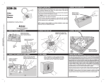
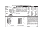
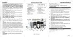
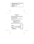
PRINTER’S INSTRUCTIONS:
INSTR,INSTL,MC3089 ,1 CH,TX - LINEAR P/N: 215641 B - INK: BLACK - MATERIAL: 20 LB. MEAD BOND - SIZE: 9.000” X 3.500” - SCALE: 1-1 - SIDE 1 OF 2
OPERATIONAL CHECK
To check operation, move back a reasonable distance (about 50 ft.) and press
the transmitter button. Operation should be reliable at this distance but
environment and location of both the transmitter and receiver will affect the
range. If the transmitter is stowed well out of sight, it may be necessary to
remove it from its mounting and hold near the windshield. Try different locations
and positions. If operation is still unsatisfactory, the problem may be isolated by:
1. Checking the door operator. If the door will not open when the wall button is
pressed, the problem is likely to be the operator. If the door will open by pressing
the wall button, but not when the radio control button is pressed, the problem is
probably in the radios.
2. Replacing the transmitter battery. If after performing the above operational
checks, the controls still do not function, they should be returned to your dealer for
repair or replacement.
CAUTION: Any changes or modifications in intentional or unintentional radiators
which are not expressly approved by LINEAR LLC could void the user’s authority
to operate this equipment. This applies to intentional and unintentional radiators
certified per Part 15 of the F.C.C. rules and regulations.
LINEAR LLC
(800) 421-1587 • (760) 438-7000
www.linearcorp.com
Copyright © 2008 Linear LLC
215641 B
®
INSTALLATION INSTRUCTIONS
DIGITAL TRANSMITTER MODEL 3089
Congratulations! You have just purchased a MULTI-CODE Digital Transmitter,
which we believe to be the finest product of its kind on the market. With a little
care this transmitter should provide you with many years of excellent service.
Please take a moment to read the following instructions and you will find that setting
your new transmitter will be quite an easy matter.
ACCESSING THE CODE SWITCH
Insert a small coin into the slot located at the bottom end of the transmitter. Twist
the coin and remove the access cover to expose the code switch and battery
compartment.
PRINTER’S INSTRUCTIONS:
INSTR,INSTL,MC3089 ,1 CH,TX - LINEAR P/N: 215641 B - INK: BLACK - MATERIAL: 20 LB. MEAD BOND - SIZE: 9.000” X 3.500” - SCALE: 1-1 - SIDE 2 OF 2
SELECTING A CODE
TRANSMITTER INSTALLATION
You may set your transmitter to any code you desire but be sure that the code you
set matches the code that has been set on your radio receiver. The digital code
is determined by the positions of the 10 small switches numbered 1 through 10
located in the receiver and transmitter. Any combination of ON (CLOSED) or OFF
(OPEN) positions can be selected by using a small screwdriver or ball point pen.
(NOTE: The switches are in the “On” position when the side next to the number
is pressed in.) In setting your own personal code we strongly urge that several
coding schemes be avoided: ALL ON; ALL OFF; 2,4,6,8,10 ON; 1,3,5,7,9 ON.
These positions are similar to our or other manufacturer’s test positions, or are
frequently used. Once the code has been set, check the operation and replace
the hatches.
The transmitter is completely self contained, including battery, and can be
operated while mounted in the car. It is supplied with a clip for attaching to the
sun visor, if desired. If the clip is used attach to the case by sliding it into the
recess provided on the back of the transmitter until the small dimples fit into the
holes in the clip.
TRANSMITTER BATTERY REPLACEMENT
Replacement battery - 9 volt NEDA 1604 (Eveready 216 or equivalent).
The battery in the transmitter can be checked or changed by removing the front
lower half of the transmitter. Refer to the directions under “accessing the code
switch” for battery replacement.
8
9
10
TO REPLACE OR ADD A SET
4
5
6
7
1
2
3
A replacement or new transmitter or receiver may be purchased by specifying the
Model Number and the RF frequency designated on the identification label. The
RF frequency is set at the factory and must not be adjusted in the field. The digital
code can be matched to the companion receiver or transmitter by following the
above procedure.