1
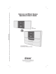
VMC1
Video Security Intercom
& Music System
Quick Start Guide
VMC1
Video Security Intercom
system for the home
USA & Canada (800) 421-1587 & (800) 392-0123
(760) 438-7000 - Toll Free FAX (800) 468-1340
www.linearcorp.com
VMC1 Quick Start Guide
SAFETY WARNING
CAUTION
RISK OF ELECTRIC SHOCK
DO NOT OPEN
CAUTION: TO REDUCE THE RISK
OF ELECTRIC SHOCK, DO NOT
REMOVE
COVER
(OR
BACK).
NO USER-SERVICEABLE PARTS
INSIDE, REFER SERVICING TO
QUALIFIED SERVICE PERSONNEL.
CAUTION!
The exclamation point within an equilateral triangle is intended to alert
the user to the presence of important operating and maintenance
(servicing) instructions in the literature accompanying the product.
SHOCK WARNING!
The lightning flash with arrowhead symbol within an equilateral triangle
is intended to alert the user to the presence of un-insulated “dangerous
voltage” within the product’s enclosure that may be of sufficient magnitude
to constitute a risk of electric shock to persons.
READ ALL INSTRUCTIONS CAREFULLY BEFORE INSTALL
OR USE THE VMC1 MUST BE INSTALLED BY TRAINED DEALERS OR INSTALLERS, AND MUST CONFORM TO ALL LOCAL
BUILDING AND ELECTRICAL CODES
Warning: Always follow these safety instructions. Retain these instructions
for future system reference.
DO NOT expose the VMC1 to moisture or fire or shock hazards can occur,
and impair the warranty.
DO NOT expose Stations to direct water spray or damage will occur
DO NOT attempt to service this product yourself as opening or removing
covers may expose you to dangerous voltage or other hazards and will
invalidate your warranty. Neither the Master Station nor the Room Stations
contain any user-serviceable parts. REFER ALL SERVICING TO QUALIFIED SERVICE PERSONNEL. USE ONLY M&S Systems replacement
parts and have them installed by an M&S Systems dealer or installer. Unauthorized substitutions can result in fire, electric shock, or other hazards
and will void the warranty.
Upon completion of any service or product repair, the M&S Systems
dealer or installer should conduct a safety check to ensure safe operating
condition.
Use only a dry cloth to clean the Master Station, Room Stations
Door Stations, and speakers. Do not use liquid cleaners or aerosol
cleaners.
TO Clean Video and Camera lens, use a clean dry cloth only
CAUTION RISK OF ELECTRIC SHOCK DO NOT OPEN CAUTION: TO REDUCE
THE RISK OF ELECTRIC SHOCK, DO NOT REMOVE COVER (OR BACK). NO
USER-SERVICEABLE PARTS INSIDE, REFER SERVICING TO
QUALIFIED SERVICE PERSONNEL.
VMC1 Quick Start Guide
Table of Contents
Quick Start Guide: Intercom ... . . . . . . . . . . . . . . . . . . . . . . . . . . . . . . . . . . . .2
Intercom Functions... . . . . . . . . . . . . . . . . . . . . . . . . . . . . . . . . . . . . . . . . .2
Quick Start Guide: Music & Audio... . . . . . . . . . . . . . . . . . . . . . . . . . . . . . . . .4
Quick Start Guide: Clock Radio... . . . . . . . . . . . . . . . . . . . . . . . . . . . . . . . . . .6
Master Station Video Display Operation... . . . . . . . . . . . . . . . . . . . . . . . . . . . . .7
Quick Start Guide: Video ... . . . . . . . . . . . . . . . . . . . . . . . . . . . . . . . . . . . . .7
NightStand Station – Audio Input... . . . . . . . . . . . . . . . . . . . . . . . . . . . . . . . . .8
Help Menu... . . . . . . . . . . . . . . . . . . . . . . . . . . . . . . . . . . . . . . . . . . . . .8
Optional Functions... . . . . . . . . . . . . . . . . . . . . . . . . . . . . . . . . . . . . . . . . .8
Quick Start Guide: Options... . . . . . . . . . . . . . . . . . . . . . . . . . . . . . . . . . . . . .8
Master Station Power Up... . . . . . . . . . . . . . . . . . . . . . . . . . . . . . . . . . . . . 10
Initial Power-Up... . . . . . . . . . . . . . . . . . . . . . . . . . . . . . . . . . . . . . . . . . 10
Programming Steps... . . . . . . . . . . . . . . . . . . . . . . . . . . . . . . . . . . . . . . . 10
Master Station Diagram... . . . . . . . . . . . . . . . . . . . . . . . . . . . . . . . . . . . . . 11
Intercom Keypad ... . . . . . . . . . . . . . . . . . . . . . . . . . . . . . . . . . . . . . . . . . 12
LED Indicator Lights... . . . . . . . . . . . . . . . . . . . . . . . . . . . . . . . . . . . . . . . 13
Limited Warranty... . . . . . . . . . . . . . . . . . . . . . . . . . . . . . . . . . . . . . . . . . 14
__ (lower)
+ (higher)
VOLUME
AUX 1
AUX 2 INPUT FILTER
VID 1
VID 2 VID 3
LOCK
GREEN Status
PRIV
MON
MUS
RED Status
CLEAR HOUSE DOOR AUX
Keep this manual in a safe place for future reference. If you lose the manual, you can
download it from the Linear Web site: www.linearcorp.com
1
Quick Start Guide: Intercom
Intercom Functions
The VMC1 Video Security Intercom System can initiate “private” room
to room conversations and whole house conversations or pages. To
respond to a call or page, there are no buttons to press. The response
at all stations are “hands free” and there is no need to stop what you
are doing.
NOTE: Door Stations calls are only initiated from the Door Station.
Room to Room Calling
All Stations in the VMC1 system have an ID number. Press
this number to talk or page another station and have a “private”
conversation.
Create Groups
Multiple Room Stations can be programmed with the same ID to
create a “Group”. Groups are treated like a single Room Station.
Depending on your specific installation and requirements, your Stations
may he programmed for a single digit or double digit ID. If you have
more than seven (7) interior Stations, including the Master, or use
AUX OUTPUTS from a Nightstand Station, your system should be
programmed for Double Digit Operation.
Single Digit Operation:
In Single Digit Operation, all Stations have an ID from 1 to 7
corresponding to the numbered buttons at all Stations.
1. Press Station call number to talk to that station. Green Status
LED lights up at that station and the RED Status LED blinks at all
Stations indicating that the system is active.
Note that only one conversation can be active at a time.
2. Release the button and wait for a response.
3. The response from the Paged Station is hands free.
4. To initiate a response from the Paging Station,
press the digit again.
5. To end the conversation, press CLEAR.
6. Twenty seconds after last button press, system
times out and RED Status LED light turns OFF.
2
Quick Start Guide: Intercom
Double Digit Operation
In Double Digit Operation,
all Stations have an I.D. from:
Press two digits for the Station to talk to. RED Status
LED blinks at all Stations to indicate the VMC1 system
is active.
11 to 17
21 to 27
or 31 to 37
NOTE: Only one conversation can be active at a time.
7. Release the button and wait for a response. Response from the
Paged Station is hands-free.
8. To answer back from the Paged Station, press 2nd
digit again.
9. To terminate the conversation, press CLEAR.
10. System times out after 20 seconds after last button
press. RED Status LED turns off.
Whole House Calling
1. To initial a whole house Page to all Stations, press
HOUSE and speak into the microphone.
2. All responses are hands free.
3. To continue the conversation press HOUSE and
speak.
4. To end the conversation, press CLEAR.
5. System times out after 20 seconds after pressing
the last button press. RED Status LED turns OFF.
Other Intercom Functions
Listen to Music or access Audio/Monitor Input:
1. Press MUS button at Master or Room Station to
enable that station speaker. RED Status LED lights
up to show it is active. Any audio input, other
Intercom conversations, are heard thru speaker.
Received Intercom Page overrides any audio for the
duration of the conversation.
2. Press MUS again to turn off
Monitor a Room Station
1. Press MON button at the Master or any Room
Station to enable that station’s speaker microphone.
GREEN Status LED lights up to indicate the room is
being monitored. All Stations where MUS is active
(RED STATUS LED lights up) can hear audio from the monitored
location(s). Multiple Stations can be monitored simultaneously.
2. Press MON again to turn off.
3
Quick Start Guide: Music & Audio
NOTE: VMC1 does not distinguish between audio from a room being monitored and
audio from the tuner. If a room is to be monitored, it is recommended that the
tuner be turned off.
Set Volume Level at Master Station
To change the speaker volume at the Master Station:
1. Turn Radio ON to provide an audio source
2. Press MUS button to activate speaker at the Master Station
3. Press Volume + (plus) or Volume – (minus) buttons to adjust level
Setting Volume Levels at Room Stations:
To change the speaker volume at any Room Station:
1. Press the Volume + or Volume – buttons to adjust level
Room station will emit a steady tone increasing or decreasing in level
depending on the button being pressed.
This tone eliminates the need to have
__ (lower)
+ (higher)
an audio source active at the Master
Station while setting the desired volume
VOLUME
level.
Your installer may disable this tone at
PLUS + & MINUS each room station, however doing so
will require an active audio source at
the Master Unit to set the volume levels. If this is disabled, follow the
steps under Setting the Volume Level at the Master Station to set the
volume levels at the Room Stations.
Privacy
Press PRIV button to disable microphone
This prevents any audio from transmitting. The Station continues to
receive calls, however.
Point-To-Point and Whole House pages.
Page any Station where Privacy is active by following the
Room-To-Room or Whole House Paging instructions.
Answer Calls in Privacy Mode:
1. Press and release PRIV button to speak. Station now functions
normally.
2. Press and release the PRIV button again to end conversation.
Station remains in Privacy mode until disabled.
3. Press the PRIV button to disable Privacy Mode.
4
Quick Start Guide: Music & Audio
Turn Audio Off
VOLUME buttons at each station control the audio volume for that
station however some audio will still be heard even with the volume
adjusted to minimum.
To turn Audio OFF at any station:
Press and hold the MUS button.
Red light begins to flash slowly.
To turn the Audio ON,
Press the MUS button. Red light turns off.
Radio Operation
Tune Radio
1. Press POWER button at the master station to turn the radio on.
2. Press BAND button to select AM or FM.
3. Press DOWN & UP buttons to tune the desired radio frequency.
Store Radio Stations
VMC1 saves up to ten AM and ten FM stations.
1. Press Band to select AM or FM
2. Press and release MEM button
3. Press and release the radio station channel. For locations 1 to
5, simply press that button.
4. Press and release the 5+ button and then select a button from 1
to 5 to select location 6 to 10 For example pressing 5+ and 1 will
save the station in location 6.
5. Press MEM to store the radio station in the selected location
Recall Stored Radio Station
1. Press BAND button to select AM or FM
2. To recall locations 1 through 5, press the desired location
3. To recall locations 6 through 10, press and release 5+
4. Immediate press a button from 1 to 5 corresponding to the desired
location. Pressing 1 will recall location 6, pressing 2 will recall
location 7 and so on.
5. Press ME-UP to scroll through all 10 stored locations. This scrolls
the stored locations and rolls back to number 1 when 10 is reached
Set Radio Alarm / Auto On Off
1. With the time displayed, press and hold the ALARM button.
Display changes from current time to alarm time with the minutes
blinking
5
Quick Start Guide: Clock Radio
2. Use the DOWN and UP buttons to adjust the desired minutes for
the alarm operation
3. Press the ALARM button again to switch to hours. The Hours will
begin to blink
4. Use the DOWN and UP buttons to adjust the desired hour for the
alarm to activate
5. Press the ALARM button again. The clock display will indicate the
alarm status; ON or OFF
6. Press DOWN or UP to toggle between ON and OFF
7. Press ALARM to exit programming
8. If the Tuner is not selected, AUX followed by INPUT
9. Activate MUS at all Stations where the Radio Alarm to be heard
When the Alarm is on, the clock will display a large “O” on the far right
of the display.
At the designated time the Master will turn on the tuner at the
designated alarm time. Only those rooms where MUS is active will the
music be heard.
If the Radio is on and the selected Alarm time is reached, the Radio
will turn off.
Radio Filter
To reduce background noise or radio interference on the radio, the
Master Station is equipped with a frequency noise filter to adjust or
reduce treble.
Press AUX button followed by number 4 button at Master to
activate the filter. The Radio Filter Led will illuminate when the filter is
turned on. To disable the filter, Press AUX followed by the 4 button
again.
NOTE: Filter only affects audio from the AM/FM radio.
Enable Aux Music
To enable the Aux music there is a 3.5mm input jack on
the Master Station as the audio source:
1. Press and release AUX
2. Press and release INPUT
Green AUX INPUT LED lights up and then Green TUNER LED will turn
off. This overrides the Radio as the source to all Stations with MUS
activated. To revert to Radio input, simply repeat steps 1 and 2 .
6
Quick Start Guide: Video
Master Station Video
Display Operation
To see the camera view for any of
the three attached cameras on the
Master Station:
1. Press AUX followed by the
desired video source
2. Press 5 for VID1,
3. 6 for VID2
4. 7 for VID3
The image remains on the Master Station display for 40 minutes, at
which time the display will turn off.
NOTE: This will not affect the VIDEO OUT signal.
To change the view:
• Press AUX followed by the desired video source
button.
To turn off the display:
• Press AUX followed by the active video source.
If a Video Door Station chime is activated, the Master Station Video
display is active, that door station camera will display on the Master
Station video display for 20 seconds then revert to the previously
selected view.
Video Out Control
From any room station, you can select a a video source to output to VIDEO OUT. This
video can be viewed from any TV in the house. This cannot be done from the Master
Station.
To select a source:
1. Press AUX 5 for Video Source 1
2. AUX 6 for Video Source 2
3. AUX 7 for Video Source
If a video door chime is activated, the Video out switches to the Door
camera for a preprogrammed period of time. To turn off the video
source, press AUX (active video source)
7
Quick Start Guide: Options
NightStand Station – Audio Input
The NightStand Station can be used as a stand-alone MP3 player/
smartphone speaker.
To listen to your auxiliary audio device:
1. Plug the appropriate cable for the selected audio device fitted with
a 3.5mm stereo plug at one end into the Audio Input Socket at the
bottom of the NightStand Station
2. Plug the other end of the cable into an MP3 player or smartphone
3. Switch Audio Source Selector at the bottom of the NightStand
Station toward the center of the Station.
4. Select Music mode on the NightStand Station by
pressing the MUS button
5. Ensure that the MP3 player or smartphone is turned
on and playing
6. With the volume of the NightStand Station set to
the normal level for communication, adjust the output volume on
the MP3 player or smartphone so the volume from the NightStand
Station is at the desired level
NOTE: With the switch positioned towards the center of the Station, the NightStand Station will not
play any music from the Master Station or any audio from Monitored Stations. All other functions
will continue to function normally.
Help Menu
The HELP MENU summarizes the 2nd function of certain
keypad buttons in conjunction with the AUX button.
1. Press and release the AUX button twice to view the
help menu
2. Press the VOLUME + and – buttons to navigate
between pages
3. Press CLEAR to exit the menu
NOTE: See P.2 of Help menu to view the second function of certain keypad buttons in conjunction with
the ‘7’ button (Applicable to Double Digit format Only)
Optional Functions
The VMC1 Security Intercom is equipped with functions that require
additional accessories. Ask you installer if these functions are enabled
at your installation.
Gate/Door Status LED
This RED LED on the Master station may be configured to indicate if a
door or gate is open or closed.
8
Quick Start Guide: Options
Door Release
The VMC1 Security Intercom System supports up to three remote
electronic door release mechanisms.
To activate a door release:
1. Press the Door Chime button at a Video Door Station. The RED
Status LED blinks at all Stations indicating an active Page
2. Press and hold DOOR button at any interior Station to speak to the
visitor.
3. Release to listen: Green Status LED lights at that
station to indicate an active microphone.
4. Release the DOOR button and light goes off.
NOTE: No other Stations can communicate once the door is answered by another Station
5. The visitor responds hands free
6. Press LOCK button to activate electronic door
release.
Door lock remains open for four (4) seconds, and
then locks.
NOTE: Press LOCK again to reopen as long as the communication is active
Only the responding Station can activate the door release, preventing accidental door opening when
pressing LOCK button
Home Automation
VMC1 Security Intercom System supports two 3-Control Output
switches for AUX Output Operation:
• Remotely turn on lights
• Trigger an alert on an alarm panel
• Activate environmental controls
With AUX Output Operations, homeowners can activate home
automation functions using the following controls:
Single Digit
• Press AUX
• Followed by button 1 for AUX 1 or button 2 for AUX2.
Double Digit
• Press 7
• Followed by button 1 for AUX 1 or 2 for AUX 2
9
Master Station Power Up
Master Station
The VMC 1 Master Station Console is the central unit for the Video Intercom
system and has a video screen to monitor any door equipped with a camera.
From the Master Unit, users can program music, add auxiliary devices like
MP3 players and computers to enhance functions, and speak to visitors ringing
the doorbell as well as see them.
Initial Power-Up
When you power-up, the master station displays a blue
welcome screen showing the applicable software version.
1. Press CLEAR* to clear screen
Enter Program Mode
2. Press PRIV and MON buttons* simultaneously.
1*
2*
4*
GENERAL OPTIONS menu is displayed.
3.
4.
5.
6.
Navigate in PROGRAM MODE
Press plus or minus buttons* to navigate up or down
Press up or down keys* to alter value
Use PREV/NEXT MENU to navigate between menus
5*
FILTER
LOCK
Programming Steps
To program your VMC1 system, please refer to the Finish
Out Guide that came with your installation package.
10
Master Station Diagram
2
1
5
4
6
7
3
8
10
9
11
Table 1 Master Station Functions
Key Description
Button
Primary Function Aux Function
1
Display for Clock Radio
Clock Radio
Keypad
Shows Time
Shows Radio
Station
2
Clock Radio Keypad
Band
Switch AM/FM
3
5.6 Color LCD
Video screen
5,6,7
VID 1,2,3
Displays Video
Displays Door
Video Cam
4
Speaker
Volume Keys
(See#6)
Radio Output
Monitored Room
Output
5
Intercom Keypad
See Table 2
6
Volume controls
7
LED Indicator Lights
8
Audio Jack input
Mp3/iPod
9
MICROPHONE
Green LED
Plus/Minus keypad buttons
See Table 3
MON
10
LED Status Lights
11
Up/Down Arrow
Green- Talk/ Red - Busy
Navigate thru menu
FILTER
LOCK
11
Intercom Keypad
Buttons/Icons
Table 2 Intercom Keypad Function
Keys
Number Keys
Primary
Function
Volume Control
(L) Low to (M)
Medium to (H)
High
Sets volume
at Master for
Radio and
Intercom
1-7
Station ID
Aux 1
Aux Function
Program Mode
Auxilliary Function
Aux 2
Input
Filter
Arrow Up
FILTER
LOCK
LOCK
12
Unlocks
Door
PRIV
Privacy
control
MON
Monitor
MUS
Music
CLEAR
Clears
intercom
HOUSE
Whole
House Page
DOOR
Talk to Door
AUX
Switches
AUX on/off
Arrow Down
Exit Program Mode
LED Indicator Lights
LED Lights (Light emitting Diodes)
indicate status or activity by alerting user
with
ON/OFF functions, blinking or flashing to
indicate active status, and auxiliary music
sources are active. They are the status
lights for the system and are these colors
when not functioning:
Tuner - Green
Aux Music - Green
Radio Filter- Green
Door Status - Red
Aux 1 - Yellow
Aux 2 - Yellow
Table 3 LED Indicator Lights
Master Station
LED LIGHT
Function
TUNER
Steady Green
Radio Source Selected
AUX MUSIC
Steady Green
Auxiliary music input
source selected
RADIO FILTER
Steady Green
Radio filter on
DOOR STATUS
Steady Red
Door is open
AUX OUTPUT 1
Steady Yellow
Auxiliary relay 1 activated
AUX OUTPUT 1
Steady Yellow
Auxiliary relay 2 activated
Master & Room Stations
Green Status Light
Blinking/flashing
Privacy - Microphone
Muted
Green Status Light
Steady
Microphone active;
monitoring ON
Red Status light
Blinking
Privacy - Microphone
Muted
Red Status light
Steady
Audio source playing/
Intercom function active
13
Limited Warranty
2-Year Limited Warranty
Linear LLC warrants these products to be free of defects for 2 years. The
warranty period begins on either (a) the date of purchase or installation date of this product
or (b) the date of closing on a new residence in which this product was originally installed.
The warranty extends to the original user of the product and to each subsequent owner of
the product during the term of the warranty. Linear LLC will repair or replace, at its option,
parts and materials at no charge. Parts supplied under this warranty may be new or rebuilt
at the option of Linear LLC.
If during the warranty period the product appears to have a defect, please call your local
dealer or installer prior to dismantling. Dismantling the product prior to calling our service
number may void the warranty. Before returning any product to Linear LLC, contact your
local dealer or distributor. Linear LLC will return the repaired product freight prepaid within
the continental United States. There are no obligations or liabilities on the part of Linear LLC for
consequential damages arising out of or in connection with use or performance of this product
or other indirect damages with respect to loss of property, revenue, or profit, or cost of removal,
installation, or reinstallation.
ANY PRODUCT RETURNED TO LINEAR LLC WITHOUT A RPA NUMBER
WILL BE REFUSED. This limited warranty is in lieu of any other warranties,
express or implied, including any implied warranty of merchantability or fitness
for a particular purpose or otherwise, and of any other obligations or liability
on the seller’s part. This limited warranty does not cover damage caused by
improper installation, acts of God, criminal acts, the violation of applicable
building or electrical codes or the use of non-recommended wire, cable
(excluding CAT5 and RG-6) or wall housings.
Under no circumstances shall Linear LLC be liable for consequential,
incidental or special damages arising in connection with use, or inability to use this
product. In no event shall Linear LLC liability hereunder exceed the cost of the product
covered hereby. No person is authorized to assume for us or obligate us for any other
liability in connection with the sale of this product. Some states do not allow the exclusion
or limitation of consequential, incidental or special damages, so the above limitation or
exclusion may not apply to you. This limited warranty gives you specific legal rights, and
you may also have other rights, which vary from state to state. This Linear LLC Warranty is in
lieu of all other warranties express or implied.
Copyright © 2012 Linear LLC
USA & Canada (800) 421-1587 & (800) 392-0123
(760) 438-7000 - Toll Free FAX (800) 468-1340
www.linearcorp.com
P1445X2