1
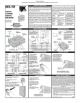
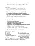
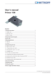
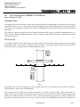
Southwest Microwave, Inc.
9055 S. McKemy Street
Tempe, AZ 85284
(480) 783-0201 Fax (480) 783-0401
TECHNICAL NOTE # 900
Re:
Access Control Pad to INTREPID™ Series II Devices
Date: February 15, 2012
INTRODUCTION
This technical note will explain how to add an access control switch box into the Intrepid Series II system. This will allow
an authorized user to “access” a zone for entry into the secured area. This method would typically be used for unmanned
sites such as power substations, VIP homes, etc. where the INTREPID Series II system relay contacts are monitored by an
alarm panel.
The switch box can take on many forms from a simple key activated switch, keypad, card reader, fingerprint scanner, etc.
There are many off the shelf products that offer a variety of features, but the switch must provide an isolated relay contact
that can be monitored.
TYPICAL USE
An example would be a VIP residence where the owner needs to enter and exit the property along the driveway without
setting off the alarm. They could use a keypad, as shown in Figure 1, at the gate to shunt the alarm for some fixed time
period as they enter or exit, then the zone would automatically secure.
Figure 1
Depending on the site layout and the type of sensors installed, there are several possible ways to connect a switch box.
Several options are shown in the following figures.
Each example shows a keypad but the switch box could be a card reader, proximity reader, finger print scanner, etc.
Figure 2 shows that the keypad is being used to control a gate lock with the main relay while also monitoring the gate
position switch and the request to exit switch. This is a typical application for the switch box. Many of them have a
second relay available that can be used to access a zone or a sensor in the INTREPID Series II system. The door lock
Tech Note # 900
2/20/12
wiring is shown since the timing of the main and aux relays will need to be configured for proper operation. Typically,
the “Aux” relay is programmed to activate for a preset amount of time, which is longer than the door lock is activated.
The time should be long enough to allow for opening and closing the gate, passing through the zone, and allowing the
sensor time to reset. The selected keypad must provide this option when used with a door lock.
Figure 2
SHUNTING AT THE SENSOR
One option is to use the keypad to directly bypass the sensor before it is connected into the INTREPID™ Series II system.
This is possible with a sensor that has a relay output that is connected into the AIM II or PM II. Examples would be a
microwave sensor, passive infrared sensor, active IR sensor, door contact, or many other devices. Figure 3 shows a
simple way to shunt the sensors relay. This can be wired for N.C. contacts as well. With this method, the INTREPID
Series II system will not be aware that someone entered the site, and therefore will not record anything into the event
history records.
Keypad
Gate Position Switch
Request to Exit Switch
Microwave or
other sensor
Door Lock
Main
Aux
Gnd
Input 1
AIM II or PM II
Figure 3
Page 2 of 5
Tech Note # 900
02/20/12
SHUNTING AT THE ALARM PANEL
Figure 4 should be followed when there is a need to access sensors that do not use relays to interface with the
INTREPID™ Series II system. Examples would be MicroPoint II, MicroTrack II, and the MicroWave 330. Other
situation calling for this method include: accessing of multiple zones and accessing remotely located equipment. This
method will also provide an event history record when used with the CM II or the GCM II control module, but not with
the RCM II.
First, set up the following Zone Record in the controller. The input(s) and output(s) are based on the site layout. There
may be more than one input and more than one output assigned.
Zone Name:
Comment:
Input:
Output:
Shunt Control
Monitors the keypad and trips the shunt relay(s)
AIM II – Input #1
(based on site layout)
ROM II 8 – Relay #1
(based on site layout)
This zone will monitor the assigned input (AIM II – Input 1) and will trip the assigned relay (ROM II-8 – Relay 1) as
required. This is used as the shunt relay. This shunt relay will stay activated as long as the input is active. The Masking
time is set by adjusting the hold time on the keypads Aux Relay.
Using the shunt Relay will temporarily prevent the zone alarm from being seen by the customers alarm panel as shown in
Figure 4. In this example the MicroPoint II is assigned to relay 1, MicroTrack II to relay 2, and the MicroWave 330
assigned to relay 3. When the shunt relay is active, all three of these zones will be disabled.
Keypad
Gate Position Switch
Request to Exit Switch
Door Lock
Main
Aux
Gnd
The INTREPID Series II
Controller will monitor the
input from the keypad and
will trip the Shunt Relay. All
zones wired through this
Shunt Relay we be
temporarily disabled.
Input 1
AIM II or PM II
RCM II, CM II, ROM II-8 or ROM II-16
Shunt
Gnd
Zone 1
Zone 2 Zone 3
Customers alarm panel inputs
Figure 4
Page 3 of 5
Tech Note # 900
02/20/12
The CM II and the GCM II will store an event history record that will log an event each time the keypad is activated. It
will show up as the Shunt Control zone programmed above. The CM II and the GCM II will also record the zone alarm
that has been shunted. Note that the RCM II does not have an event record, but will function in the same way as described
here.
EXAMPLE USING MODEL 2000e SERIES KEYPAD
The following description details the basic programming of the Linear Corporations model 2000 series e/eM keypad.
Further information can be found online at http://www.linearcorp.com/product_detail.php?productId=1225
The wiring diagrams shown in Figures 1, 2, 3 and 4 apply directly to this product. For proper operation, follow the
keypad programming steps described below.
PROGRAMMING
The following programming steps detail the minimum process needed for configuring the keypads output relays and
adding users.
Before commands can be entered, you must log in as the master user. This is done by pressing the following:
99 # mastercode*
*
enter programming mode (master code = 1234)
(Enter the programming commands below)
exit programming mode
Restore Factory Defaults – This keypad does not provide a way of reviewing the current settings or the existing user list.
It is best to start by restoring the defaults. This will also erase all existing user data. Enter the command:
46 # 00000 # 00000 #**
Remove the ‘Aux Relay’ from the ‘Lock Output’ Assignment – By default, the Aux Relay is assigned to follow the
main Lock Output Relay function. They need to be separate to individually control the Aux Relay timing. Enter the
following code:
10 # 2 # 0 #**
Assign the ‘Aux Relay’ to ‘OUT 2’ Assignment - Each user will be assigned to trip both the Main Lock Relay and the
relay assigned to ‘OUT 2’. The Aux Relay needs to be assigned to OUT 2. Enter the following code:
10 # 5 # 2 #**
Set the ‘Aux Relay’ Hold Time – This will control the Alarm Shunt Time. Set the time to allow for full passage through
gate and zone, plus time for the alarm to reset. To set the time, pick two numbers (ttt and mmm) that, when multiplied
together, equals the desired time in seconds. For example, selecting ttt = 3 and mmm = 5 gives 15 seconds for the alarm
shunt.
12 # ttt # mmm #**
Assign the ‘Request to Exit’ Input to both ‘Main Relay’ and ‘OUT 2’ – This allows exiting the secure area without
having to re-enter a code. A button would be placed on the secure side of the crossing, before any of the sensors. Enter
the following:
49 # 12 # 0 #**
Page 4 of 5
Tech Note # 900
02/20/12
Program all Users – Each user should be entered with the following format. The ‘12’ indicates that the user will trip the
Main Lock relay and the OUT 2 relay assignment (Aux Relay) whenever the code is entered. The User Location is the ID
of the user. User Location 1 is the master, 2 is the supervisor, and 3 – 500 are general users. The user codes can be from
4 to 10 digits long.
59 # 12 # user location # code * code *
The above programming steps will configure the keypad to properly control the Aux Relay so it can be used to “Shunt” a
zone or zones while also controlling a gate lock. There are many other features of the keypad that can be implemented as
well. See the user manual for this product for further information.
Page 5 of 5
Tech Note # 900
02/20/12