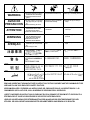
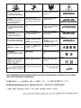
1
RETURN TO MAIN MENU
POWER WAVE 455
™
For use with machines having Code Numbers:
IM583-A
December, 1999
10372, 10553, 10555
Safety Depends on You
Lincoln arc welding and cutting
equipment is designed and built
with safety in mind. However, your
overall safety can be increased by
proper installation ... and thoughtful operation on your part. DO
NOT INSTALL, OPERATE OR
REPAIR THIS EQUIPMENT
WITHOUT READING THIS
MANUAL AND THE SAFETY
PRECAUTIONS CONTAINED
THROUGHOUT. And, most
importantly, think before you act
and be careful.
Date of Purchase:
Serial Number:
Code Number:
Model:
Where Purchased:
R
OPERATOR’S MANUAL
• World's Leader in Welding and Cutting Products •
• Sales and Service through Subsidiaries and Distributors Worldwide •
Cleveland, Ohio 44117-1199 U.S.A. TEL: 216.481.8100 FAX: 216.486.1751 WEB SITE: www.lincolnelectric.com
i
i
SAFETY
WARNING
CALIFORNIA PROPOSITION 65 WARNINGS
Diesel engine exhaust and some of its constituents
are known to the State of California to cause cancer, birth defects, and other reproductive harm.
The Above For Diesel Engines
The engine exhaust from this product contains
chemicals known to the State of California to cause
cancer, birth defects, or other reproductive harm.
The Above For Gasoline Engines
ARC WELDING CAN BE HAZARDOUS. PROTECT YOURSELF AND OTHERS FROM POSSIBLE SERIOUS INJURY OR DEATH.
KEEP CHILDREN AWAY. PACEMAKER WEARERS SHOULD CONSULT WITH THEIR DOCTOR BEFORE OPERATING.
Read and understand the following safety highlights. For additional safety information, it is strongly recommended that you
purchase a copy of “Safety in Welding & Cutting - ANSI Standard Z49.1” from the American Welding Society, P.O. Box
351040, Miami, Florida 33135 or CSA Standard W117.2-1974. A Free copy of “Arc Welding Safety” booklet E205 is available
from the Lincoln Electric Company, 22801 St. Clair Avenue, Cleveland, Ohio 44117-1199.
BE SURE THAT ALL INSTALLATION, OPERATION, MAINTENANCE AND REPAIR PROCEDURES ARE
PERFORMED ONLY BY QUALIFIED INDIVIDUALS.
FOR ENGINE
powered equipment.
1.h. To avoid scalding, do not remove the
radiator pressure cap when the engine is
hot.
1.a. Turn the engine off before troubleshooting and maintenance
work unless the maintenance work requires it to be running.
____________________________________________________
1.b.Operate engines in open, well-ventilated
areas or vent the engine exhaust fumes
outdoors.
____________________________________________________
1.c. Do not add the fuel near an open flame
welding arc or when the engine is running.
Stop the engine and allow it to cool before
refueling to prevent spilled fuel from vaporizing on contact with hot engine parts and
igniting. Do not spill fuel when filling tank. If
fuel is spilled, wipe it up and do not start
engine until fumes have been eliminated.
____________________________________________________
1.d. Keep all equipment safety guards, covers
and devices in position and in good
repair.Keep hands, hair, clothing and tools
away from V-belts, gears, fans and all other
moving parts when starting, operating or
repairing equipment.
____________________________________________________
1.e. In some cases it may be necessary to remove safety
guards to perform required maintenance. Remove
guards only when necessary and replace them when the
maintenance requiring their removal is complete.
Always use the greatest care when working near moving
parts.
___________________________________________________
1.f. Do not put your hands near the engine fan. Do not attempt
to override the governor or idler by pushing on the throttle
control rods while the engine is running.
___________________________________________________
1.g. To prevent accidentally starting gasoline engines while
turning the engine or welding generator during maintenance
work, disconnect the spark plug wires, distributor cap or
magneto wire as appropriate.
ELECTRIC AND
MAGNETIC FIELDS
may be dangerous
2.a. Electric current flowing through any conductor causes
localized Electric and Magnetic Fields (EMF). Welding
current creates EMF fields around welding cables and
welding machines
2.b. EMF fields may interfere with some pacemakers, and
welders having a pacemaker should consult their physician
before welding.
2.c. Exposure to EMF fields in welding may have other health
effects which are now not known.
2.d. All welders should use the following procedures in order to
minimize exposure to EMF fields from the welding circuit:
2.d.1. Route the electrode and work cables together - Secure
them with tape when possible.
2.d.2. Never coil the electrode lead around your body.
2.d.3. Do not place your body between the electrode and
work cables. If the electrode cable is on your right
side, the work cable should also be on your right side.
2.d.4. Connect the work cable to the workpiece as close as
possible to the area being welded.
2.d.5. Do not work next to welding power source.
Mar ‘95
ii
ii
SAFETY
ELECTRIC SHOCK can
kill.
3.a. The electrode and work (or ground) circuits
are electrically “hot” when the welder is on.
Do not touch these “hot” parts with your bare
skin or wet clothing. Wear dry, hole-free
gloves to insulate hands.
3.b. Insulate yourself from work and ground using dry insulation.
Make certain the insulation is large enough to cover your full
area of physical contact with work and ground.
In addition to the normal safety precautions, if welding
must be performed under electrically hazardous
conditions (in damp locations or while wearing wet
clothing; on metal structures such as floors, gratings or
scaffolds; when in cramped positions such as sitting,
kneeling or lying, if there is a high risk of unavoidable or
accidental contact with the workpiece or ground) use
the following equipment:
• Semiautomatic DC Constant Voltage (Wire) Welder.
• DC Manual (Stick) Welder.
• AC Welder with Reduced Voltage Control.
3.c. In semiautomatic or automatic wire welding, the electrode,
electrode reel, welding head, nozzle or semiautomatic
welding gun are also electrically “hot”.
3.d. Always be sure the work cable makes a good electrical
connection with the metal being welded. The connection
should be as close as possible to the area being welded.
3.e. Ground the work or metal to be welded to a good electrical
(earth) ground.
3.f. Maintain the electrode holder, work clamp, welding cable and
welding machine in good, safe operating condition. Replace
damaged insulation.
3.g. Never dip the electrode in water for cooling.
3.h. Never simultaneously touch electrically “hot” parts of
electrode holders connected to two welders because voltage
between the two can be the total of the open circuit voltage
of both welders.
3.i. When working above floor level, use a safety belt to protect
yourself from a fall should you get a shock.
3.j. Also see Items 6.c. and 8.
ARC RAYS can burn.
4.a. Use a shield with the proper filter and cover
plates to protect your eyes from sparks and
the rays of the arc when welding or observing
open arc welding. Headshield and filter lens
should conform to ANSI Z87. I standards.
4.b. Use suitable clothing made from durable flame-resistant
material to protect your skin and that of your helpers from
the arc rays.
4.c. Protect other nearby personnel with suitable, non-flammable
screening and/or warn them not to watch the arc nor expose
themselves to the arc rays or to hot spatter or metal.
FUMES AND GASES
can be dangerous.
5.a. Welding may produce fumes and gases
hazardous to health. Avoid breathing these
fumes and gases.When welding, keep
your head out of the fume. Use enough
ventilation and/or exhaust at the arc to keep
fumes and gases away from the breathing zone. When
welding with electrodes which require special
ventilation such as stainless or hard facing (see
instructions on container or MSDS) or on lead or
cadmium plated steel and other metals or coatings
which produce highly toxic fumes, keep exposure as
low as possible and below Threshold Limit Values (TLV)
using local exhaust or mechanical ventilation. In
confined spaces or in some circumstances, outdoors, a
respirator may be required. Additional precautions are
also required when welding on galvanized steel.
5.b. Do not weld in locations near chlorinated hydrocarbon vapors
coming from degreasing, cleaning or spraying operations.
The heat and rays of the arc can react with solvent vapors to
form phosgene, a highly toxic gas, and other irritating
products.
5.c. Shielding gases used for arc welding can displace air and
cause injury or death. Always use enough ventilation,
especially in confined areas, to insure breathing air is safe.
5.d. Read and understand the manufacturer’s instructions for this
equipment and the consumables to be used, including the
material safety data sheet (MSDS) and follow your
employer’s safety practices. MSDS forms are available from
your welding distributor or from the manufacturer.
5.e. Also see item 1.b.
Mar ‘95
iii
iii
SAFETY
WELDING SPARKS can
cause fire or explosion.
6.a. Remove fire hazards from the welding area.
If this is not possible, cover them to prevent
the welding sparks from starting a fire.
Remember that welding sparks and hot
materials from welding can easily go through small cracks
and openings to adjacent areas. Avoid welding near
hydraulic lines. Have a fire extinguisher readily available.
6.b. Where compressed gases are to be used at the job site,
special precautions should be used to prevent hazardous
situations. Refer to “Safety in Welding and Cutting” (ANSI
Standard Z49.1) and the operating information for the
equipment being used.
6.c. When not welding, make certain no part of the electrode
circuit is touching the work or ground. Accidental contact
can cause overheating and create a fire hazard.
6.d. Do not heat, cut or weld tanks, drums or containers until the
proper steps have been taken to insure that such procedures
will not cause flammable or toxic vapors from substances
inside. They can cause an explosion even though they have
been “cleaned”. For information, purchase “Recommended
Safe Practices for the Preparation for Welding and Cutting of
Containers and Piping That Have Held Hazardous
Substances”, AWS F4.1 from the American Welding Society
(see address above).
6.e. Vent hollow castings or containers before heating, cutting or
welding. They may explode.
6.f. Sparks and spatter are thrown from the welding arc. Wear oil
free protective garments such as leather gloves, heavy shirt,
cuffless trousers, high shoes and a cap over your hair. Wear
ear plugs when welding out of position or in confined places.
Always wear safety glasses with side shields when in a
welding area.
6.g. Connect the work cable to the work as close to the welding
area as practical. Work cables connected to the building
framework or other locations away from the welding area
increase the possibility of the welding current passing
through lifting chains, crane cables or other alternate circuits. This can create fire hazards or overheat lifting chains
or cables until they fail.
6.h. Also see item 1.c.
CYLINDER may explode
if damaged.
7.a. Use only compressed gas cylinders
containing the correct shielding gas for the
process used and properly operating
regulators designed for the gas and
pressure used. All hoses, fittings, etc. should be suitable for
the application and maintained in good condition.
7.b. Always keep cylinders in an upright position securely
chained to an undercarriage or fixed support.
7.c. Cylinders should be located:
• Away from areas where they may be struck or subjected to
physical damage.
• A safe distance from arc welding or cutting operations and
any other source of heat, sparks, or flame.
7.d. Never allow the electrode, electrode holder or any other
electrically “hot” parts to touch a cylinder.
7.e. Keep your head and face away from the cylinder valve outlet
when opening the cylinder valve.
7.f. Valve protection caps should always be in place and hand
tight except when the cylinder is in use or connected for
use.
7.g. Read and follow the instructions on compressed gas
cylinders, associated equipment, and CGA publication P-l,
“Precautions for Safe Handling of Compressed Gases in
Cylinders,” available from the Compressed Gas Association
1235 Jefferson Davis Highway, Arlington, VA 22202.
FOR ELECTRICALLY
powered equipment.
8.a. Turn off input power using the disconnect
switch at the fuse box before working on
the equipment.
8.b. Install equipment in accordance with the U.S. National
Electrical Code, all local codes and the manufacturer’s
recommendations.
8.c. Ground the equipment in accordance with the U.S. National
Electrical Code and the manufacturer’s recommendations.
Mar ‘95
iv
iv
SAFETY
PRÉCAUTIONS DE SÛRETÉ
Pour votre propre protection lire et observer toutes les instructions
et les précautions de sûreté specifiques qui parraissent dans ce
manuel aussi bien que les précautions de sûreté générales suivantes:
Sûreté Pour Soudage A L’Arc
1. Protegez-vous contre la secousse électrique:
a. Les circuits à l’électrode et à la piéce sont sous tension
quand la machine à souder est en marche. Eviter toujours
tout contact entre les parties sous tension et la peau nue
ou les vétements mouillés. Porter des gants secs et sans
trous pour isoler les mains.
b. Faire trés attention de bien s’isoler de la masse quand on
soude dans des endroits humides, ou sur un plancher
metallique ou des grilles metalliques, principalement dans
les positions assis ou couché pour lesquelles une grande
partie du corps peut être en contact avec la masse.
c. Maintenir le porte-électrode, la pince de masse, le câble
de soudage et la machine à souder en bon et sûr état
defonctionnement.
d.Ne jamais plonger le porte-électrode dans l’eau pour le
refroidir.
e. Ne jamais toucher simultanément les parties sous tension
des porte-électrodes connectés à deux machines à souder
parce que la tension entre les deux pinces peut être le
total de la tension à vide des deux machines.
f. Si on utilise la machine à souder comme une source de
courant pour soudage semi-automatique, ces precautions
pour le porte-électrode s’applicuent aussi au pistolet de
soudage.
2. Dans le cas de travail au dessus du niveau du sol, se protéger
contre les chutes dans le cas ou on recoit un choc. Ne jamais
enrouler le câble-électrode autour de n’importe quelle partie
du corps.
3. Un coup d’arc peut être plus sévère qu’un coup de soliel,
donc:
a. Utiliser un bon masque avec un verre filtrant approprié
ainsi qu’un verre blanc afin de se protéger les yeux du rayonnement de l’arc et des projections quand on soude ou
quand on regarde l’arc.
b. Porter des vêtements convenables afin de protéger la
peau de soudeur et des aides contre le rayonnement de
l‘arc.
c. Protéger l’autre personnel travaillant à proximité au
soudage à l’aide d’écrans appropriés et non-inflammables.
4. Des gouttes de laitier en fusion sont émises de l’arc de
soudage. Se protéger avec des vêtements de protection libres
de l’huile, tels que les gants en cuir, chemise épaisse, pantalons sans revers, et chaussures montantes.
5. Toujours porter des lunettes de sécurité dans la zone de
soudage. Utiliser des lunettes avec écrans lateraux dans les
zones où l’on pique le laitier.
6. Eloigner les matériaux inflammables ou les recouvrir afin de
prévenir tout risque d’incendie dû aux étincelles.
7. Quand on ne soude pas, poser la pince à une endroit isolé de
la masse. Un court-circuit accidental peut provoquer un
échauffement et un risque d’incendie.
8. S’assurer que la masse est connectée le plus prés possible
de la zone de travail qu’il est pratique de le faire. Si on place
la masse sur la charpente de la construction ou d’autres
endroits éloignés de la zone de travail, on augmente le risque
de voir passer le courant de soudage par les chaines de levage, câbles de grue, ou autres circuits. Cela peut provoquer
des risques d’incendie ou d’echauffement des chaines et des
câbles jusqu’à ce qu’ils se rompent.
9. Assurer une ventilation suffisante dans la zone de soudage.
Ceci est particuliérement important pour le soudage de tôles
galvanisées plombées, ou cadmiées ou tout autre métal qui
produit des fumeés toxiques.
10. Ne pas souder en présence de vapeurs de chlore provenant
d’opérations de dégraissage, nettoyage ou pistolage. La
chaleur ou les rayons de l’arc peuvent réagir avec les vapeurs
du solvant pour produire du phosgéne (gas fortement toxique)
ou autres produits irritants.
11. Pour obtenir de plus amples renseignements sur la sûreté,
voir le code “Code for safety in welding and cutting” CSA
Standard W 117.2-1974.
PRÉCAUTIONS DE SÛRETÉ POUR
LES MACHINES À SOUDER À
TRANSFORMATEUR ET À
REDRESSEUR
1. Relier à la terre le chassis du poste conformement au code de
l’électricité et aux recommendations du fabricant. Le dispositif
de montage ou la piece à souder doit être branché à une
bonne mise à la terre.
2. Autant que possible, I’installation et l’entretien du poste seront
effectués par un électricien qualifié.
3. Avant de faires des travaux à l’interieur de poste, la debrancher à l’interrupteur à la boite de fusibles.
4. Garder tous les couvercles et dispositifs de sûreté à leur
place.
Mar. ‘93
v
v
Thank You
for selecting a QUALITY product by Lincoln Electric. We want you
to take pride in operating this Lincoln Electric Company product
••• as much pride as we have in bringing this product to you!
Please Examine Carton and Equipment For Damage Immediately
When this equipment is shipped, title passes to the purchaser upon receipt by the carrier. Consequently, Claims
for material damaged in shipment must be made by the purchaser against the transportation company at the
time the shipment is received.
Please record your equipment identification information below for future reference. This information can be
found on your machine nameplate.
Model Name & Number _____________________________________
Code & Serial Number _____________________________________
Date of Purchase
_____________________________________
Whenever you request replacement parts for or information on this equipment always supply the information
you have recorded above.
Read this Operators Manual completely before attempting to use this equipment. Save this manual and keep it
handy for quick reference. Pay particular attention to the safety instructions we have provided for your protection.
The level of seriousness to be applied to each is explained below:
WARNING
This statement appears where the information must be followed exactly to avoid serious personal injury or
loss of life.
CAUTION
This statement appears where the information must be followed to avoid minor personal injury or damage to
this equipment.
vi
TABLE OF CONTENTS
Page
Installation .......................................................................................................Section A
Technical Specifications - Power Wave 455..........................................................A-1
Safety Precautions.................................................................................................A-2
Select Suitable Location ........................................................................................A-2
Stacking ..........................................................................................................A-2
Environmental Protection ................................................................................A-2
Lifting...............................................................................................................A-2
Machine Grounding ...............................................................................................A-2
High Frequency Protection ....................................................................................A-2
Input Connection....................................................................................................A-2
Input Fuse and Supply Wire Considerations .........................................................A-3
Input Voltage Reconnect Procedure......................................................................A-3
Output Connections ...............................................................................................A-3
Voltage Sensing at the Work Piece .......................................................................A-4
Power Wave / Power Feed Wire Feeder Interconnections....................................A-4
Electrode and Work Leads - Electrode Positive Applications .........................A-4
Electrode and Work Leads - Electrode Negative Applications........................A-4
Control Cable Connections .............................................................................A-4
Power Feed Control Box Mounting .................................................................A-4
Operation .........................................................................................................Section B
Safety Instructions .................................................................................................B-1
Graphic Symbols that appear on this machine or in this manual...........................B-2
General Description ...............................................................................................B-3
Recommended Processes and Equipment ...........................................................B-3
Design Features and Advantages .........................................................................B-3
Additional Features................................................................................................B-3
Welding Capability .................................................................................................B-4
Limitations..............................................................................................................B-4
Compatible Lincoln Equipment ..............................................................................B-4
Power Source Operation .......................................................................................B-4
Duty Cycle and Time Period ...........................................................................B-4
Case Front Controls ........................................................................................B-4
Welding Adjustments ......................................................................................B-5
Detailed Weld Mode Descriptions ...................................................................B-5
Accessories .....................................................................................................Section C
Options / Accessories............................................................................................C-1
Factory Installed..............................................................................................C-1
Field Installed..................................................................................................C-1
Maintenance ....................................................................................................Section D
Safety Precautions ................................................................................................D-1
Routine Maintenance.............................................................................................D-1
Troubleshooting ..............................................................................................Section E
Troubleshooting the Power Wave / Power Feed System using the Status LED ...E-1
Safety Precautions.................................................................................................E-2
How to Use Troubleshooting Guide.......................................................................E-2
Troubleshooting Guide ..........................................................................................E-3
Wiring Diagram and Dimension Print ............................................................Section F
Parts Lists ....................................................................................................P291 Series
Nov97
A-1
A-1
INSTALLATION
TECHNICAL SPECIFICATIONS - POWER WAVE 455
INPUT AT RATED OUTPUT - THREE PHASE ONLY
INPUT VOLTS
OUTPUT
CONDITIONS
INPUT
CURRENT
OUTPUT
CONDITIONS
INPUT
CURRENT
208V - 60HZ.
230V - 60HZ.
400V - 60HZ.
460V - 60HZ.
575V - 60HZ.
200V - 50HZ.
220V - 50HZ.
400V - 50HZ.
440V - 50HZ.
550V - 50HZ.
450A@38V. 100%
450A@38V. 100%
450A@38V. 100%
450A@38V. 100%
450A@38V. 100%
400A@36V. 100%
400A@36V. 100%
400A@36V. 100%
400A@36V. 100%
400A@36V. 100%
70
65
39
35
29
72
67
40
36
29
570A@43V. 60%
570A@43V. 60%
570A@43V. 60%
570A@43V. 60%
570A@43V. 60%
500A@40V. 60%
500A@40V. 60%
500A@40V. 60%
500A@40V. 60%
500A@40V. 60%
87
82
50
48
38
79
74
45
41
33
OUTPUT
OPEN
CIRCUIT
VOLTAGE
CURRENT
RANGE
PULSE
FREQUENCY
PULSE
VOLTAGE
RANGE
PULSE AND
BACKGROUND
TIME RANGE
AUXILIARY
POWER
75 VDC
5 - 570
0.15 - 1000 Hz
5 - 55 VDC
100 MICRO SEC. 3.3 SEC.
40 VDC AT
10 AMPS
115 VAC AT
10 AMPS
PROCESS CURRENT RANGES (DC)
CURRENT
MIG/MAG
FCAW
SMAW
Pulse
50-570 Amps
40-570 Amps
30-570 Amps
5-750 Amps
RECOMMENDED INPUT WIRE AND FUSE SIZES
INPUT
VOLTAGE /
FREQUENCY
208/60
230/60
400/60
460/60
575/60
200/50
220/50
400/50
440/50
550/50
OUTPUT AMPS/ INPUT AMPERE
DUTY
RATING ON
CYCLE
NAMEPLATE
450/100%
450/100%
450/100%
450/100%
450/100%
400/100%
400/100%
400/100%
400/100%
400/100%
70
65
39
35
29
72
67
35
31
29
TYPE 75°C
TYPE 75°C
TYPE 75°C
COPPER WIRE GROUND WIRE (SUPER LAG)
IN CONDUIT
IN CONDUIT
OR BREAKER
AWG[IEC] SIZES AWG[IEC] SIZES SIZE (AMPS)
(MM2)
(MM2)
4 (25)
8 (10)
80 AMP
4 (25)
8 (10)
70 AMP
8 (10)
10 (6)
50 AMP
8 (10)
10 (6)
40 AMP
8 (10)
10 (6)
40 AMP
4 (25)
8 (10)
80 AMP
4 (25)
8 (10)
80 AMP
8 (10)
10 (6)
50 AMP
8 (10)
10 (6)
40 AMP
8 (10)
10 (6)
40 AMP
PHYSICAL DIMENSIONS
HEIGHT
26.10 in
663 mm
WIDTH
19.86 in
505 mm
DEPTH
32.88 in
835 mm
WEIGHT
250 lbs.
114 kg.
TEMPERATURE RANGES
OPERATING TEMPERATURE RANGE
0°C to 40°C
STORAGE TEMPERATURE RANGE
-50°C to 85°C
POWER WAVE 455
A-2
A-2
INSTALLATION
Read this entire installation section before you
start installation.
SAFETY PRECAUTIONS
WARNING
ELECTRIC SHOCK can kill.
ENVIRONMENTAL PROTECTION
The Power Wave power source is rated IP21S and
should not be subjected to falling water, nor should
any parts of it be submerged in water. Doing so may
cause improper operation as well as pose a safety
hazard. The best practice is to keep the machine in a
dry, sheltered area.
• Only qualified personnel should
perform this installation.
• Turn the input power OFF at the
disconnect switch or fuse box
before working on this equipment.
• Do not touch electrically hot parts.
• Always connect the Power Wave grounding lug
(located inside the reconnect input access door) to
a proper safety (Earth) ground.
-------------------------------------------------------------
SELECT SUITABLE LOCATION
Place the welder where clean cooling air can freely
circulate in through the rear louvers and out through
the case sides and bottom. Dirt, dust, or any foreign
material that can be drawn into the welder should be
kept at a minimum. Using filters on the air intake to
prevent dirt from building up restricts air flow. Do
not use such filters. Failure to observe these precautions can result in excessive operating temperatures
and nuisance shutdowns.
This machine (above code 10500 only) is equipped
with F.A.N. (fan as needed) circuitry. The fan runs
whenever the output is enabled, whether under
loaded or open circuit conditions. The fan also runs for
a period of time (approximately 5 minutes) after the
output is disabled, to ensure all components are properly cooled.
If desired, the F.A.N. feature can be disabled (causing
the fan to run whenever the power source is on). To
disable F.A.N., connect leads 444 and X3A together
at the output of the solid state fan control relay, located on the back of the Control PC board enclosure.
STACKING
Power Wave machines can be stacked to a maximum
of 3 high. The bottom machine must always be
placed on a firm, secure, level surface. There is a
danger of machines toppling over if this precaution is
not taken.
LIFTING
Lift the machine by the lift bail only. The lift bail is
designed to lift the power source only. Do not attempt
to lift the Power Wave with accessories attached to it.
MACHINE GROUNDING
The frame of the welder must be grounded. A ground
terminal marked with the symbol
is located inside
the reconnect/input access door for this purpose. See
your local and national electrical codes for proper
grounding methods.
HIGH FREQUENCY PROTECTION
If possible, locate the Power Wave away from radio
controlled machinery. The normal operation of the
Power Wave may adversely affect the operation of RF
controlled equipment, which may result in bodily injury
or damage to the equipment.
INPUT CONNECTION
WARNING
Only a qualified electrician should connect the input
leads to the Power Wave. Connections should be
made in accordance with all local and national electrical codes and the connection diagram located on the
inside of the reconnect/input access door of the
machine. Failure to do so may result in bodily injury
or death.
------------------------------------------------------------Use a three-phase supply line. A 1.75 inch (45 mm)
diameter access hole for the input supply is located on
the upper left case back next to the input access door.
Connect L1, L2, L3 and ground according to the Input
Supply Connection Diagram decal located on the
inside of the input access door or refer to Figure A.1
following.
POWER WAVE 455
A-3
A-3
INSTALLATION
FIGURE A.1 - CONNECTION DIAGRAM ON RECONNECT/INPUT ACCESS DOOR
S24196
INPUT SUPPLY CONNECTION DIAGRAM
440-460V
not touch electrically live parts.
Only qualified persons should install,
use or service this equipment.
.
VOLTAGE=220-230V
VOLTAGE=380-415V
200-208V
200-208V
220-230V
380-415V
200-208V
220-230V
’A’
380-415V
220-230V
’A’
380-415V
440-460V
440-460V
’A’
not touch electrically live parts.
Only qualified persons should install,
use or service this equipment.
VOLTAGE=440-460V
440-460V
VOLTAGE=550-575V
’A’
550-575V
440-460V
550-575V
’A’
A
A
440-460V
VOLTAGE=440-460V
not operate with covers
removed.
. Do
U.S.A.
. Do
’A’
CR1
U / L1
CLEVELAND, OHIO
380-415V
inspecting or servicing machine.
THE LINCOLN ELECTRIC CO.
220-230V
U / L1
not operate with covers
removed.
CLEVELAND, OHIO
before
inspecting or servicing machine.
. Do
V / L2
before
. Do
THE LINCOLN ELECTRIC CO.
. Disconnect input power
200-208V
CR1
. Disconnect input power
.
V / L2
U.S.A.
VOLTAGE=200-208V
W / L3
S23847
W / L3
INPUT SUPPLY CONNECTION DIAGRAM
NOTE: Turn main input power to the machine OFF before performing reconnect procedure. Failure to do
so will result in damage to the machine. DO NOT switch the reconnect bar with machine power ON.
INPUT FUSE AND SUPPLY WIRE
CONSIDERATIONS
Refer to the Technical Specifications at the beginning
of this Installation section for recommended fuse and
wire sizes. Fuse the input circuit with the recommended super lag fuse or delay type breakers (also called
“inverse time” or “thermal/magnetic” circuit breakers).
Choose an input and grounding wire size according to
local or national electrical codes. Using fuses or circuit breakers smaller than recommended may result in
“nuisance” shut-offs from welder inrush currents, even
if the machine is not being used at high currents.
instructions located on the inside of the input access
door or in Figure A.1. If the main reconnect switch is
placed in the wrong position, the welder will not produce output power. If the Auxiliary (“A”) lead is placed
in the wrong position, there are two possible results.
If the lead is placed in a position higher than the
applied line voltage, the welder may not come on at
all. If the Auxiliary (“A”) lead is placed in a position
lower than the applied line voltage, the welder will not
come on, and the two circuit breakers in the reconnect
area will open. If this occurs, turn off the input voltage, properly connect the “A” lead, reset the breakers,
and try again.
OUTPUT CONNECTIONS
INPUT VOLTAGE RECONNECT
PROCEDURE
WARNING
Only a qualified electrician should connect the input
leads to the Power Wave. Connections should be
made in accordance with all local and national electrical codes and the connection diagram located on the
inside of the reconnect/input access door of the
machine. Failure to do so may result in bodily injury or
death.
-----------------------------------------------------------------------Welders are shipped connected for the highest input
voltage listed on the rating plate. To move this connection to a different input voltage, refer to reconnect
Use the largest welding (electrode and ground) cables
possible — at least 2/0, 4/0 preferred, copper wire —
even if the average output current would not normally
require it. When pulsing, the pulse current can
exceeds 650 amps. Voltage drops can become
excessive, leading to poor welding characteristics, if
undersized welding cables are used.
To avoid interference problems with other equipment
and to achieve the best possible operation, route all
cables directly to the work or wire feeder. Avoid
excessive lengths, bundle the electrode and ground
cables together where practical, and do not coil
excess cable.
POWER WAVE 455
A-4
INSTALLATION
A-4
VOLTAGE SENSING AT THE
WORKPIECE
POWER WAVE / POWER FEED WIRE
FEEDER INTERCONNECTIONS
A four-pin work piece voltage sense lead connector is
located beneath the output stud cover. The use of a
work piece sense lead is optional for most welding
modes, but may be used if desired.
ELECTRODE & WORK LEADS —
ELECTRODE POSITIVE APPLICATIONS
Sense Lead Kits (K490-10, -25 or -50) are available
for this purpose.
To enable the work piece voltage sensing lead, a
jumper must be removed from the Control PC Board
as follows:
1) Turn the Power Wave 455 power OFF.
2) Remove the front nameplate from the Power Wave
455 by removing the six screws from the nameplate. Save the screws for re-use.
3) Locate P26, located on the upper right edge of the
Control PC Board. It is a 16 pin connector with
only two wires going into it. Unplug P26. It should
remain attached to the main harness.
4) Install the front nameplate on the Power Wave 455
by replacing the six screws saved in Step 2.
5) Plug a Sense Lead into the Sense Lead
Receptacle. Note: Only the lead marked ‘WORK’
is used. The lead marked ‘ELECT’ can be cut off
and discarded.
6) Connect the WORK sense lead clamp to the piece
being welded.
The Power Wave 455 will now use the external work
piece Sense Lead to sense arc voltage in all welding
modes. If the Sense Lead is enabled but not connected to the work piece, extremely high welding output
currents may result.
To restore normal work piece sensing (at the output
terminals) reconnect P26 to the Control PC board.
The Sense Lead can then be disconnected.
Most welding applications run with the electrode being
positive (+). For those applications, connect the electrode cable between the wire feeder and the positive
(+) output stud on the power source (located beneath
the spring loaded output cover near the bottom of the
case front).
A work lead must be run from the negative (-) power
source output stud to the work piece. The work piece
connection must be firm and secure, especially if
pulse welding is planned. Excessive voltage drops at
the work piece connection often result in unsatisfactory pulse welding performance.
ELECTRODE & WORK LEADS —
ELECTRODE NEGATIVE APPLICATIONS
When negative electrode polarity is required, such as
in some Innershield™ applications, install as above,
except reverse the output connections at the power
source (electrode cable to the negative (-) stud, and
work cable to the positive (+) stud).
CONTROL CABLE CONNECTIONS
Connect the control cable between the wire feeder
and power source. The power source wire feeder
connection is located under the spring loaded output
cover, near the bottom of the case front. The control
cable is keyed and polarized, so it can be installed in
only one way.
For neatness and convenience sake, both the electrode and control cables can be routed behind the left
or right strain reliefs (under the spring loaded output
cover), and along the channels formed into the base
of the Power Wave, out the back of the channels, and
then to the wire feeder.
POWER WAVE 455
A-5
INSTALLATION
POWER FEED CONTROL BOX
MOUNTING
In some installations, it may be desirable to mount the
Wire Feeder control box directly to the front of the
Power Wave power source. (The control box is the
box containing the knobs, switches and displays necessary to control the Power Wave / Power Feed welding system.) Complete details for separating the control box from the wire drive are contained in the Power
Feed Instruction Manual. Once separated, mounting
instructions are as follows:
1. Disconnect the input power from the Power Wave.
2. Separate the control box from the wire drive on the
Power Feed wire feeder, and remove the control
panels (see the Power Feed Instruction Manual for
details).
3. Remove the front nameplate from the Power Wave
by removing six screws from the metal nameplate.
Save the screws for re-use.
4. Connect the 6-pin connector that comes out the
back of the control box to the 6-pin receptacle that
is tie-wrapped to the harnessing inside the rectangular opening in the power source. It will be necessary to remove one or two of the wire ties in
order to give enough slack to the power source
connector and leads.
5. Position the control box over the rectangular hole
in the Power Wave case front, being careful not to
pinch any leads between the control box and the
case front. Align the four holes in the back of the
control box with the four threaded mounting holes
in the case front. Secure the control box in place
with four of the screws saved from the previous
step.
6. Reassemble the control box.
The Power Feed Wire Drive can now be connected to
the power source wire feeder connector. This connector is located under the spring loaded output
cover, near the bottom of the case front. The control
cable is keyed and polarized, so it can be installed in
only one way. (To ensure proper electrode voltage
sensing, always connect the Wire Drive to the Power
Source wire feeder connector. Do not connect it to
the optional Output Receptacle which may be present
on the Power Feed Control Box.)
POWER WAVE 455
A-5
B-1
OPERATION
OPERATING INSTRUCTIONS
Read and understand this entire section of operating
instructions before operating the machine.
SAFETY INSTRUCTIONS
WARNING
ELECTRIC SHOCK can kill.
• Do not touch electrically live parts or
electrodes with your skin or wet clothing.
• Insulate yourself from the work and ground.
• Always wear dry insulating gloves.
FUMES AND GASES can be
dangerous.
• Keep your head out of fumes.
• Use ventilation or exhaust to remove
fumes from breathing zone.
WELDING SPARKS can cause
fire or explosion.
• Keep flammable material away.
• Do not weld on containers that have held combustibles.
ARC RAYS can burn.
• Wear eye, ear, and body protection.
Observe additional Safety Guidelines
detailed in the beginning of this manual.
POWER WAVE 455
B-1
B-2
OPERATION
GRAPHIC SYMBOLS THAT APPEAR ON
THIS MACHINE OR IN THIS MANUAL
INPUT POWER
SMAW
ON
GMAW
OFF
FCAW
HIGH TEMPERATURE
GTAW
MACHINE STATUS
U0
OPEN CIRCUIT
VOLTAGE
CIRCUIT BREAKER
U1
INPUT VOLTAGE
WIRE FEEDER
U2
OUTPUT VOLTAGE
POSITIVE OUTPUT
I1
INPUT CURRENT
NEGATIVE OUTPUT
I2
OUTPUT CURRENT
3 PHASE INVERTER
PROTECTIVE
GROUND
INPUT POWER
THREE PHASE
WARNING
DIRECT CURRENT
POWER WAVE 455
B-2
B-3
B-3
OPERATION
GENERAL DESCRIPTION
Parameter
The Power Wave 455 is a high performance, digitally
controlled inverter welding power source capable of
complex, high-speed waveform control. Properly
equipped, it can support the GMAW, GMAW-P,
FCAW, SMAW, GTAW and CAC-A processes.
Welding
Mode
Stick Crisp, Stick Soft, Flux Cored with Gas,
Flux Cored without Gas, CV, Synergic CV,
.035 Stainless Pulse, .045 Steel Pulse, 5356
Aluminum Pulse
Output
Current (CC modes), Voltage (CV modes),
Wire Feed Speed (synergic modes)
RECOMMENDED PROCESSES AND
EQUIPMENT
Trim
.500 to 1.500 (only in Pulse modes)
Arc Control
-10.0 to +10.0
RECOMMENDED PROCESSES
ADDITIONAL DESIGN FEATURES AND
ADVANTAGES
The Power Wave can be set up in a number of configurations, some requiring optional equipment. Each
machine is factory preprogrammed with multiple welding procedures, typically including GMAW, GMAW-P,
FCAW, SMAW, GTAW and CAC-A, for a variety of
materials, including mild steel, stainless steel, cored
wires, and aluminum.
Examples
• Designed to NEMA EW-1, IEC 974-1 and CSA
Standards.
• Qualifies for “S” mark on nameplate, which means it
can be used in areas where there is increased risk
of electric shock.
RECOMMENDED EQUIPMENT
• Multiple process output ranges: 5 - 570 amps.
The Power Wave 455 must be used with the Power
Feed family of wire feeders. These feeders are
required to access and make use of the many of the
welding features contained in the Power Wave 455.
• Easy access for input connections. Connections
are simple strip and clamp (no lugs required).
DESIGN FEATURES AND ADVANTAGES
A unique feature of the Power Wave is the ability to
function without any controls, when used with Power
Feed wire feeders. All power source control information comes to the Power Wave from a Power Feed
wire feeder.
The following chart lists the power source parameters
that can be changed from the Power Feed wire feeder, and gives examples of each. (Optional equipment
may be required to access some of the following parameters.)
• F.A.N. (fan as needed). (On codes above 10500
only) Cooling fan runs only when necessary.
• Modular construction for easy servicing.
• Thermostatically protected.
• Electronic over current protection.
• Input over voltage protection.
• Utilizes digital signal processing and microprocessor
control.
• Simple, reliable input voltage change over.
• All system components communicate and transfer
information.
• Auto device recognition simplifies accessory cable
connections.
POWER WAVE 455
B-4
B-4
OPERATION
WELDING CAPABILITY
CASE FRONT CONTROLS
The POWER WAVE 455 is rated at 60 Hz. 450A@
38V. 100% duty cycle or 570A@ 43V 60% duty cycle 50 Hz. 400A@ 36V, 100% duty cycle or 500A@40V
60% duty cycle. The machine is capable of higher outputs at lower duty cycles.
All operator controls and adjustments are located on
the case front of the Power Wave.
If the duty cycle is exceeded, a thermostat will shut off
the output until the machine cools to a reasonable
operating temperature.
2. STATUS LIGHT: A two color light that indicates
system errors. Normal operation is a steady green
light. Error conditions are indicated as follows:
LIMITATIONS
• The Power Wave is not recommended for processes other than those listed.
• The Power Wave can only be used with Power
Feed wire feeders. Other models of Lincoln feeders, or any models of non-Lincoln wire feeders, cannot be used.
COMPATIBLE LINCOLN EQUIPMENT
1. POWER SWITCH: Controls input power to the
Power Wave.
NOTE: The Power Wave 455 status light will flash
green, and sometimes red and green, for up to one
minute when the Power Wave 455 is first turned on.
This is a normal situation as the machine goes
through a self test at power up.
Meaning
Light
Condition
Steady Green System OK. Power source communicating normally with wire feeder and its components.
Blinking
Green
Nothing connected to Wire Feeder
Receptacle.
A l t e r n a t i n g Recoverable system fault.See
Green and Troubleshooting Section.
Red
All Lincoln Power Feed™ Wire Feeders.
Steady Red
Non-recoverable system fault. Must turn
power source off, find source of error, and
turn power back on to reset. See
Troubleshooting Section.
DUTY CYCLE AND TIME PERIOD
Blinking Red
See Troubleshooting Section.
The POWER WAVE 455 is rated at 60 Hz. 450A@
38V. 100% duty cycle or 570A@ 43V 60% duty cycle 50 Hz. 400A@ 36V, 100% duty cycle or 500A@40V
60% duty cycle. The duty cycle is based upon a ten
minute period. A 60% duty cycle represents 6 minutes
of welding and 4 minutes of idling in a ten minute period.
3. HIGH TEMPERATURE LIGHT (thermal overload):
A yellow light that comes on when an over temperature situation occurs. Output is disabled until the
machine cools down. When cool, the light goes
out and output is enabled.
POWER SOURCE OPERATION
4. 10 AMP WIRE FEEDER CIRCUIT BREAKER:
Protects 40 volt DC wire feeder power supply.
5. 10 AMP AUXILIARY POWER CIRCUIT BREAKER: Protects 110 volt AC case front receptacle
auxiliary supply.
POWER WAVE 455
B-5
OPERATION
WELDING ADJUSTMENTS
All adjustments are made on the system component
known as the control box, which contains the switches, knobs and digital displays necessary to control
both the Power Wave and a Power Feed wire feeder.
Typically, the control box is supplied as part of the
wire feeder. It can be mounted directly on the wire
feeder itself, or mounted separately, as might be done
in a welding boom installation.
Because the control box can be configured with many
different options, your system may not have all of the
following adjustments. Regardless of availability, all
controls are described below. For further information,
consult the Power Feed wire feeder instruction manual.
1. WFS / AMPS:
In synergic welding modes (synergic CV, pulse
GMAW) WFS (wire feed speed) is the dominant
control parameter, controlling all other variables.
The user adjusts WFS according to factors such as
weld size, penetration requirements, heat input, etc.
The Power Wave then uses the WFS setting to
adjust its output characteristics (output voltage, output current) according to pre-programmed settings
contained in the Power Wave. In non-synergic
modes, the WFS control changes the wire feed
speed according to the desired procedure.
In constant current modes (stick, TIG) this control
adjusts the output current, in amps.
2. VOLTS / TRIM:
In constant voltage modes (synergic CV, standard
CV) the control adjusts the welding voltage.
In pulse synergic welding modes (pulse GMAW
only) the user can change the Trim setting to adjust
the arc length. It is adjustable from 0.500 to 1.500.
A Trim setting of 1.000 is a good starting point for
most conditions.
3. WELDING MODE:
May be selected by name (CV/MIG, CC/Stick Crisp,
Gouge, etc.) or by a mode number (10, 24, 71, etc.)
depending on the control box options. Selecting a
welding mode determines the output characteristics
of the Power Wave power source. For a more
complete description of the welding modes available in the Power Wave, see the explanation
below.
4. ARC CONTROL:
Also known as Inductance or Wave Control. Allows
operator to vary the arc characteristics from “soft”
to “harsh” in all weld modes. It is adjustable from -
B-5
10.0 to +10.0, with a nominal setting of 00.0. (The
nominal setting of 00.0 may be displayed as OFF
on some Power Feed wire feeder control panels.)
See the Welding Mode descriptions, below, for
detailed explanations of how the Arc Control affects
each mode.
DETAILED WELD MODE DESCRIPTIONS
CONSTANT VOLTAGE (CV/WELD, CV/MIG,
CV/FLUX CORED) PROCEDURES
For each wire feed speed, a corresponding voltage is
preprogrammed into the machine through special softwares at the factory. This preprogrammed voltage is
the best average voltage for the procedure at the
given wire feed speed. If the wire feed speed is
changed on the wire feeder, the voltage automatically
changes with it.
In some cases, the operator may want to change the
preprogrammed voltages; for example, to compensate
for cable and fixture voltage drops. The preset voltages can be adjusted on the wire feeder’s Voltage
display. When a change is made to the voltage at
one wire feed speed, this change is applied to all
other wire feed speed settings. For example, if the
operator turns up the voltage by 10 percent, the
machine automatically increases the preset voltages
at all the other wire feed speeds by 10 percent. The
preset voltage, programmed at the factory, may be
changed with the wire feeder VOLTS adjustment.
The Arc Control adjusts the inductance. (This adjustment is often referred to as “pinch”. Inductance is
inversely proportional to pinch.) Increasing the Arc
Control setting decreases the inductance, which
results in the arc getting colder and pinched tighter.
Decreasing the Arc Control setting increases the
inductance, which results in the arc getting wider
(reduced pinch).
GMAW PULSE PROCEDURES
In these procedures, the actual voltage greatly
depends on the waveform used. The peak currents,
background currents, rise times, fall times, and pulse
times all affect the actual voltage. The actual voltage
for a given wire feed speed is not directly predictable
unless the waveform is known. In this case, it is not
practical to preset an actual voltage for the procedure.
Instead, an arc length adjustment is provided. The
machine “knows” what the best arc length is at the
given wire feed speed but allows the operator to
change it.
POWER WAVE 455
B-6
OPERATION
The arc length trim (usually referred to simply as
“trim”) can be adjusted between 0.500 and 1.500 on
the control box’s Volts/Trim display. A Trim of 1.000
means that no adjustments will be made to the preset
arc lengths. A Trim greater than 1.000 increases the
preset arc lengths. A Trim setting less than 1.000
decreases the preset arc lengths. The arc length trim
adjustment is factored in at all wire feed speed settings. Increasing the Trim by 10 percent at a given
wire feed speed also increases all the other arc length
trim settings of the procedure by 10 percent.
The Power Wave utilizes a control scheme known as
adaptive control in all pulse modes. Because the
Power Wave utilizes adaptive control, it can adjust the
pulsing parameters based on changes in the arc due
to changes in the electrical stickout of the electrode.
(Electrical stickout is the distance from the contact to
to the workpiece.) The Power Wave is optimized
for use with a .75” stickout. The adaptive behavior
is programmed to support a stickout range from .5” to
1.25”. In the low and high end of the wire feed speed
ranges of most processes, the adaptive behavior may
be restricted. This is a physical restriction due to
reaching the edge of the operating range for the
process.
B-6
ARC GOUGING PROCEDURES
Arc gouging can be performed by choosing the arc
gouging weld mode. Doing so automatically energizes the output terminals on the Power Wave, making the power source immediately ready to weld. The
output current is set by the Amps control on the
Power Weld wire feeder. The Volts/Trim adjustment
has no effect in this mode.
The Arc Control adjusts the arc force. Increasing the
Arc Control setting increases the arc force, making
the arc more harsh but less likely to stick. Decreasing
the Arc Control setting decreases the arc force, making the arc softer and smoother.
The Arc Control adjustment allows the pulse frequency to be varied. Increasing the Arc Control causes the
frequency setting to increase, while decreasing the
Arc Control causes the frequency to decrease.
Varying the Arc Control, and hence, the pulse frequency, affects the droplet transfer and allows finetuning for different welding positions.
CONSTANT CURRENT (CC/STICK, CC/TIG)
PROCEDURES
Stick welding can be performed by choosing one of
the stick welding modes. Check the Power Feed wire
feeder Operator’s Manual for instructions on how to
energize the output terminals on the Power Wave.
(Certain options energize the terminals automatically
while other options require a manual adjustment to
energize the terminals.) The output current is set by
the Amps control on the Power Feed wire feeder. The
Volts/Trim adjustment has no effect in this mode.
The Arc Control adjusts the arc force. Increasing the
Arc Control setting increases the arc force, making
the arc more harsh but less likely to stick. Decreasing
the Arc Control setting decreases the arc force, making the arc softer and smoother.
POWER WAVE 455
C-1
ACCESSORIES
OPTIONS / ACCESSORIES
FACTORY INSTALLED
There are no factory installed options available for the
Power Wave machines.
FIELD INSTALLED
The following options/accessories are available for
your Power Wave from your local Lincoln Distributor.
K1570-1 Dual Cylinder Undercarriage
K940-10 Voltage Sense Lead Kit- 10 foot voltage
sense lead kit.
K940-25 Voltage Sense Lead Kit- 25 foot voltage
sense lead kit, if additional length is required.
K940-50 Voltage Sense Lead Kit- 50 foot voltage
sense lead kit, if additional length is required.
POWER WAVE 455
C-1
D-1
MAINTENANCE
SAFETY PRECAUTIONS
WARNING
ELECTRIC SHOCK can kill.
• Only Qualified personnel should
perform this maintenance.
• Turn the input power OFF at the
disconnect switch or fuse box
before working on this equipment.
•
Do not touch electrically hot parts.
ROUTINE MAINTENANCE
Routine maintenance consists of periodically
blowing out the machine, using a low pressure
airstream, to remove accumulated dust and dirt
from the intake and outlet louvers, and the cooling
channels in the machine.
POWER WAVE 455
D-1
E-1
TROUBLESHOOTING
USING THE STATUS LED TO
TROUBLESHOOT SYSTEM PROBLEMS
The Status LED on the power source case front
can help diagnose problems down to the system
component (power source, wire feeder, wire drive,
etc.) level. If, for any reason, the system does not
appear to be working properly, always check the
E-1
color of the Status LED, and refer to the following
chart to help you determine which system component (power source, wire feeder, wire drive, etc.)
may be faulty. Replace the components identified
as potentially faulty with known good components, and the system should operate normally.
Status LED is solid green (no blinking).
System operating normally.
Status LED is blinking green.
1.
Normal condition for the first few seconds after the
power is turned on.
2.
Wire feeder and/or its components are not properly configured and/or connected together. Refer
to wire feeder instruction manual(s) for wire feeder
configuration information.
1.
Indicates that nothing is connected to the Wire
Feeder Receptacle. Connect a Power Feed Wire
Feeder to the wire feeder receptacle.
2.
Power source cannot communicate with the wire
feeder and/or its components due to a problem
within the power source. Contact an authorized
Lincoln Electric Service facility.
1.
If the Thermal LED is also lit, see “Yellow Thermal
LED Lit” in the Main Troubleshooting Chart.
Input voltage is too high or too low. Make certain
that input voltage is proper, according to the
Rating Plate located on the rear of the machine.
Power source is having trouble communicating
with wire feeder or its components. Turn machine
off. Disconnect control cable from the Wire
Feeder Receptacle. Turn power back on. If
Status LED then blinks green, the problem is with
the wire feeder. If light is still blinking red and
green, contact an authorized Lincoln Field Service
facility.
Status LED is solid red (no blinking).
Status LED is blinking red and green.
2.
3.
Status LED is blinking red.
1.
Error code display. Contact an authroized Lincoln
Field Service Shop.
POWER WAVE 455
E-2
TROUBLESHOOTING
HOW TO USE TROUBLESHOOTING GUIDE
WARNING
This Troubleshooting Guide is designed to be used by the machine Owner/Operator. Unauthorized
repairs per-formed on this equipment may result in danger to the technician and machine operator and
will invalidate your factory warranty. For your safety, please observe all safety notes and precautions
detailed in the Safety Section of this manual to avoid electrical shock or danger while troubleshooting
this equipment.
This Troubleshooting Guide is provided to help
you locate and correct possible machine misadjustments. Simply follow the three-step procedure
listed below.
Step 1. LOCATE PROBLEM (SYMPTOM)
Step 3. CONSULT LOCAL AUTHORIZED
FIELD SERVICE FACILITY
If you have exhausted all of the recommended
tests in step 2, consult your local Authorized
Field Service Facility.
Look under the column labeled “PROBLEM
(SYMPTOMS).” This column describes possible
symptoms that your machine may exhibit. Find
the listing that best describes the symptom that
your machine is exhibiting.
Step 2. PERFORM EXTERNAL RECOMMENDED TESTS
The second column labeled “POSSIBLE AREAS
OF MISADJUSTMENT(S)” lists the obvious
external possibilities that may contribute to the
machine symptom. Perform these tests/checks in
the order listed. In general, these tests can be
conducted without removing the case wraparound cover.
CAUTION
If for any reason you do not understand the test procedures or are unable to perform the tests/repairs
safely, contact your local authorized Lincoln Electric Field Service Facility for technical assistance.
POWER WAVE 455
E-2
E-3
E-3
TROUBLESHOOTING
Observe all Safety Guidelines detailed throughout this manual
Observe Safety Guidelines
detailed in the beginning of this manual.
TROUBLESHOOTING GUIDE
PROBLEMS
(SYMPTOMS)
POSSIBLE AREAS OF
MISADJUSTMENT(S)
OUTPUT PROBLEMS
RECOMMENDED
COURSE OF ACTION
Major physical or electrical damage Contact your local authorized
is evident when the sheet metal
Lincoln Electric Field Service facilicovers are removed.
ty for technical assistance.
Input fuses keep blowing, or input
breaker keeps tripping.
1.
2.
3.
Machine will not power up (no
lights, no fan, etc.)
1.
2.
3.
Make certain that fuses or
breakers are properly sized.
See Installation section of this
manual for recommended
fuse and breaker sizes.
Welding procedure is drawing
too much output current, or
duty cycle is too high.
Reduce output current, duty
cycle, or both.
There is internal damage to
the power source. Contact an
authorized Lincoln Electric
Service facility.
If all recommended possible areas
of misadjustments have been
checked and the problem persists,
contact your local Lincoln
Authorized Field Service Facility.
Make certain that the Power
Switch (SW1) is in the “ON”
position.
Circuit breaker CB4 (in reconnect area) may have opened.
Reset. Also, check input voltage selection, below.
Input voltage selection made
improperly. Power down,
check input voltage reconnect
according to diagram on
reconnect cover.
CAUTION
If for any reason you do not understand the test procedures or are unable to perform the tests/repairs safely, contact your local authorized Lincoln Electric Field Service Facility for technical assistance.
POWER WAVE 455
E-4
E-4
TROUBLESHOOTING
Observe all Safety Guidelines detailed throughout this manual
Observe Safety Guidelines
detailed in the beginning of this manual.
TROUBLESHOOTING GUIDE
PROBLEMS
(SYMPTOMS)
POSSIBLE AREAS OF
MISADJUSTMENT(S)
OUTPUT PROBLEMS
Wire feeder won’t work. No lights, 1.
apparently no power to wire feeder.
2.
3.
Thermal LED is lit.
1.
2.
Machine won’t weld, can’t get any
output. (CR1 will not pull in.)
1.
2.
3.
RECOMMENDED
COURSE OF ACTION
Circuit breaker CB1 (on case
front) may have opened.
Reset.
Control cable between the
power source and wire feeder
is “open”. Check continuity on
all 5 leads from end to end in
the control cable.
Check for 40 volts DC on pins
D (+40) and E (common) of
the Wire Feeder Receptacle.
If 40 volts DC is not present,
and CB1 is reset, contact an
authorized Lincoln Electric
Service facility.
Fan thermostat has opened. Check
for proper fan operation. (Fan should
run whenever main power is on.)
Check for material blocking intake or
exhaust louvers, or for excessive dirt
clogging cooing channels in machine.
Secondary rectifier thermostat has
opened. After machine has cooled,
reduce load, duty cycle, or both.
Check for material blocking intake or
exhaust louvers.
If all recommended possible areas
of misadjustments have been
checked and the problem persists,
contact your local Lincoln
Authorized Field Service Facility.
Input voltage is too low or too high.
Make certain that input voltage is
proper, according to the Rating Plate
located on the rear of the machine.
If the Thermal LED is also lit, see
“Yellow Thermal LED is Lit” section.
Primary current limit has been
exceeded. Possible short in output
circuit. Turn machine off. Remove all
loads from the output of the machine.
Turn back on. If condition persists,
turn power off, and contact an authorized Lincoln Electric Field Service
facility.
CAUTION
If for any reason you do not understand the test procedures or are unable to perform the tests/repairs safely, contact your local authorized Lincoln Electric Field Service Facility for technical assistance.
POWER WAVE 455
E-5
E-5
TROUBLESHOOTING
Observe all Safety Guidelines detailed throughout this manual
Observe Safety Guidelines
detailed in the beginning of this manual.
TROUBLESHOOTING GUIDE
PROBLEMS
(SYMPTOMS)
POSSIBLE AREAS OF
MISADJUSTMENT(S)
OUTPUT PROBLEMS
Machine often “noodle welds” (output is limited to approximately 100
amps) when running a particular
procedure
Secondary current limit has been
exceeded, and the machine has
phased back to protect itself.
Adjust procedure or reduce load to
lower current draw from the
machine.
Machine won’t produce full output.
1.
2.
For no apparent reason, the welding characteristics have changed.
1.
2.
3.
Auxiliary receptacle is “dead” — no
auxiliary voltage .
1.
2.
RECOMMENDED
COURSE OF ACTION
Input voltage may be too low,
limiting output capability of the
power source. Make certain
that the input voltage is proper, according to the Rating
Plate located on the rear of
the machine.
Input may be “single phased”.
Make certain the input voltage
is proper on all three input
lines.
Check for proper Wire Feed
Speed setting. In CV MIG
and FCAW modes, check for
proper Voltage setting. In the
MIG/MAG pulse modes,
check the Trim setting. These
controls are on the wire feeder.
Check for proper shielding
gas mix and flow.
Check for loose or faulty weld
cables and cable connections.
If all recommended possible areas
of misadjustments have been
checked and the problem persists,
contact your local Lincoln
Authorized Field Service Facility.
Circuit breaker CB2 (on case
front) may have opened.
Reset.
Circuit breaker CB4 (in reconnect area) may have opened.
Reset.
CAUTION
If for any reason you do not understand the test procedures or are unable to perform the tests/repairs safely, contact your local authorized Lincoln Electric Field Service Facility for technical assistance.
POWER WAVE 455
3
LINE
LOAD
TO R1
206A
206
52A
A
1
33
31
251
32
206A
202A
TP3
612B
TO CB3
TO J61
H1D
TO RECONNECT PANEL
TO TP3
C2
.05/600V
L3A
J81
TO
S4
ELECTRODE
WORK
TO
TO
J81
CB2
ELECTRODE
WORK
TO
POWER BD
L2
TO
J25
TO
NOTES:
N.D
N.C.
N.B.
N.A.
2B
228
8
N.D.
1
2
234
235
503
404
506
13
11
6
5
3
4
2
1
6
5
3
4
2
1
16
15
14
13
12
11
10
9
8
7
6
5
4
3
2
53
274
273
54
J31
S1
TO
S3
254
4
1
TO
253
251
3R
3
2
1
12
AC
C3
AC
MAY NOT APPEAR ON ALL MACHINES.
CONNECTION SHOWN IS FOR 440-460V OPERATION.
PLACE "A" LEAD ON APPROPRIATE CONNECTION FOR INPUT VOLTAGE.
CONNECTION SHOWN IS FOR 380-460V OPERATION.
PLACE SWITCH IN APPROPRIATE POSITION FOR INPUT VOLTAGE.
ALIGNS WITH BLACK LEAD OF LED SOCKET.
6
POS
NEG
NEG
POS
POS
POS
X1
NEG
X2
NEG
POWER BD RECTIFIER
SOLID STATE RELAY
STATUS LED
10
9
8
TO
3W
1B
3
4
7
J60
J50
J40
6
5
1W
1
2
403
604
14
405
11
12
238
239
9
10
8
406
233
3
5
7
4
224
AUX. #1
TO
C3
N.D.
THERM
CHOKE
TO
TO J22
N.D.
TO
C3
J27
J22
TO
CB1
224A
J32
TO
TO
L2
TO J21A
TO RECT THERM
N.D.
POWER BD RECT
5
6
NEG
NEG
4
231
232
POS
POS
273
274
221
226
228
222
223
225
51
50
1
3
2
1
12
11
10
9
8
7
6
5
3
4
X3A
-
TO AUX#1
1
4
3W
2
J32
J31
51BK
50WT
TP4
TO
J24
220
TO
444
TO FAN
2
3
POWER BOARD
L7
+
3R
10
2W
226
7
9
6
LED
RECT.
THERM.
THERMAL
224
225
5
TO
J31
223
3
4
222
221
TO
P91
2
1
7
8
6
5
4
3
2
SOLID
STATE
RELAY
TRANSFORMER
CURRENT
TO
ELECTRODE
WORK
S2
PIN NEAREST THE FLAT EDGE OF LED LENS (CATHODE)
J28
J27
J26
J25
J24
J23
J22
J21B
218
7
8
1
216
6
TO
S1
1
2
3
4
THERM.
CHOKE
2.7
10W
2.7
10W
2.7
10W
2.7
10W
.022
291
220
.022
800V
D1
D2
800V
.022
THERM.
RECT.
D3
800V
.022
800V
D4
OUTPUT RECT
212
213
211
216
291
224A
F1
F1
N.D.
PRIMARY
(TOP
RIGHT)
PRIMARY
(BOTTOM
RIGHT)
PRIMARY
(BOTTOM
LEFT)
PRIMARY
(TOP
LEFT)
RIGHT SIDE
SECONDARY
(TOP
RIGHT)
SECONDARY
(BOTTOM
RIGHT)
SECONDARY
(BOTTOM
LEFT)
SECONDARY
(TOP
LEFT)
MAIN TRANSFORMER
LEFT SIDE
RIGHT SIDE OF MACHINE
TP7
F2
F2
F3
F3
F4
F4
+
P91
CURRENT
TRANSDUCER
MAIN CHOKE
L1
TO POWER BD. RECTIFIER
13
BD #1
TO SWITCH
11
TO CURRENT
TRANSFORMER
BD #2
17
TO SWITCH
TRANSFORMER
15
TO CURRENT
BD #1
14
TO SWITCH
TRANSFORMER
12
TO CURRENT
BD #2
18
TO SWITCH
TRANSFORMER
16
TO CURRENT
LEFT SIDE OF MACHINE
TO
J60
CR1
11
12
CB2
S4
TO
TO MAIN TRANS
TRANSFORMER
TO CURRENT
16
H5
TO J23
J40
C4
19C
33
32
15 16
13 14
TO J23
J50
W=WHITE
U=BLUE
R=RED
N=BROWN
G=GREEN
B=BLACK
LEAD COLOR CODING
1
4
2
3
6
RESISTORS=OHMS/WATTS
CAPACITORS=MFD/VOLTS
COMPONENT VALUES:
(200-208)
H1
(220-230)
H2
(380-415)
H3
(440-460)
H4
H5
TO RECONNECT SWITCH
(115V)
R
W
19D
ELECTRICAL SYMBOLS PER E1537
P81
4
1
20D
C5
17 18
TO L7
H2A
H3A
H4A
H5A
TO MAIN TRANS
TO RECONNECT SWITCH
20C
SWITCH BOARD #2
218
CURRENT
TRANSFORMER
214
11 12
H1
H2
H3
H4
H5
X3A
TO SOLID STATE RELAY
TO FAN
(220-230)
H2
(200-208)
H1
H3
(380-415)
(440-460)
H4
SWITCH BOARD #1
(115V)
(24V)
R
N
W
AUXILIARY TRANSFORMER #2
15
TRANSFORMER
TO CURRENT
X5
X4
X3
X3
(51V)
U
W
AUXILIARY TRANSFORMER #1
X1
X2
H4A
H5A
H1A
H2A
H3A
TO
CB3
3
1
J25
4
2
AUX #1
4
1
3
6
J50,J81
J27,J28
J32,J40
J61
J60
INPUT BOARD
1
10
9
8
7
6
5
4
3
2
1
8
5
1
J60
J21A,J21B
T3
8
4
H1D
612
T2
T1
231
6
CR1
238
7
6
10
5
7
1
12
6
TO AUX #1
X4
601
X5
TO AUX#1
8
(VIEWED FROM COMPONENT SIDE OF BOARD)
V
POS
G
TO SW1
L1A
L2
T2
AC2
TO SUPPLY LINES
L3
T3
AC3
NEG
INPUT
RECTIFIER
SWITCH
RECONNECT
U
L1
T1
14
7
9
1
AC1
POS
440-460V
G3051-1
J20,J26
NATIONAL ELECTRICAL CODE.
TO A SYSTEM GROUND PER
W
J23
L3A
TO SW1
1
TO
200-208V
220-230V
’A’
380-415V
H5
H4
H2
N.C.
H3
NEG
TO AUX #1
FAN
TO SW1
CB4
6A CIRCUIT
BREAKER
CB3
10A CIRCUIT
BREAKER
RECONNECT PANEL
CR1
TO J61
TO J60
J24,J31
TO INPUT RECT
NEG
TO SWITCH BD #1
20C
19C
TO SWITCH BD #1
N.B.
CB3
TO SOLID STATE RELAY
444
H1
TO AUX #1
612
612A
TO J61
H1A
TO AUX #2
612A
CONNECTOR CAVITY NUMBERING SEQUENCE
J22,J61
CB4
SW1
CR1
TO
AUX #1
J23
TO
X3
601
232
604
5
2
3
4
1
20D
TO SWITCH BD #2
POS
TO INPUT RECT
19D
TO SWITCH BD #2
RECONNECT SWITCH
THIS AREA VIEWED FROM REAR OF MACHINE
RECONNECT PANEL
CB4
AUX #2
TO
612B
TO SW1
TO CB4
8
16
REAR OF MACHINE
TO CONTACTOR
TO CONTACTOR
L1A
(TOP)
2
R1
20
7
5
6
50
254
3
4
253
THERMAL LED (Y)
TO J22
N.A.
S1
TO
212
213
214
2
5
3
1
J20
4
211
16
P6
J20
1
13
15
3
2
11
POWER BD
12
10
14
TO
4
206
67A
9
7
8
21A
202
6
5
4
3
CB1
J21A
J20
1
2
J27
L2
TO
CONTROL BOARD
TO
2
STATUS LED (R/G)
TO J24
N.A.
TP2
50
52
67B
5
6
21A
51A
4
1
54A
53A
51A
51
52A
52
67B
67A
3
2
1
E
D
C
54A
B
53A
53
54
A
.05/600V
C1
TO TP3
D
DIAGRAMS
NOTE: This diagram is for reference only. It may not be accurate for all machines covered by this manual. The specific diagram for a particular code is pasted inside
the machine on one of the enclosure panels. If the diagram is illegible, write to the Service Department for a replacement. Give the equipment code number..
SW1
POWER
4
2W
2B
TO J20
1W
1B
ELECTRODE
+
CB2
10A CIRCUIT
BREAKER
31
110V RECEPTACLE
S4
CB1
10A CIRCUIT
BREAKER
S3
RS232
CONNECTOR
P6
USER
TP1
INTERFACE
S2
VOLTAGE
SENSE
RECEPTACLE
S1
WIRE
FEEDER
RECEPTACLE
WORK
-
202A
TO R1
202
TO J20
233
1
234
1
WIRING DIAGRAM
403
503
TM
455
2
2
POWER WAVE
404
239
235
3
FRONT OF MACHINE
405
5
3
506
6
5
+
+
406
6
4
+
POWER WAVE 455
4
F-1
F-1
POWER WAVE 455
(TOP)
32
TO
J81
CB2
L2
N.C.
N.B.
POWER BD RECTIFIER
POWER BOARD
SOLID
STATE
RELAY
CONNECTION SHOWN IS FOR 550-575V OPERATION.
PLACE "A" LEAD ON APPROPRIATE CONNECTION FOR INPUT VOLTAGE.
CONNECTION SHOWN IS FOR 550-575V OPERATION.
PLACE SWITCH IN APPROPRIATE POSITION FOR INPUT VOLTAGE.
CONTROL BOARD
POWER WAVE
OUTPUT RECT
PRIMARY
(TOP
RIGHT)
PRIMARY
(BOTTOM
RIGHT)
PRIMARY
(BOTTOM
LEFT)
PRIMARY
(TOP
LEFT)
RIGHT SIDE
SECONDARY
(TOP
RIGHT)
SECONDARY
(BOTTOM
RIGHT)
SECONDARY
(BOTTOM
LEFT)
SECONDARY
(TOP
LEFT)
MAIN TRANSFORMER
LEFT SIDE
P91
CURRENT
TRANSDUCER
RIGHT SIDE OF MACHINE
+
MAIN CHOKE
L1
AUXILIARY TRANSFORMER #2
SWITCH BOARD #2
SWITCH BOARD #1
AUXILIARY TRANSFORMER #1
WIRING DIAGRAM
LEFT SIDE OF MACHINE
TM
455
(460 / 575V)
INPUT BOARD
13
TO SWITCH BD #1
14
TO SWITCH BD #1
17
TO SWITCH BD #2
18
TO SWITCH BD #2
TO BOTTOM LEFT PRI
14B
TO TOP RIGHT PRI
13B
TO BOTTOM LEFT PRI
14A
TO TOP RIGHT PRI
13A
TO TOP LEFT PRI
18B
TO BOTTOM RIGHT PRI
17B
TO TOP LEFT PRI
18A
TO BOTTOM RIGHT PRI
17A
RECONNECT SWITCH
THIS AREA VIEWED FROM REAR OF MACHINE
L3A
TO SW1
CR1
TO AUX #1
X4
601
TO J60
H6
H5
NEG
V
U
POS
G
TO SW1
L1A
L2
T2
AC2
TO SUPPLY LINES
L3
T3
AC3
FAN
NATIONAL ELECTRICAL CODE.
A
L1
T1
AC1
POS
REAR OF MACHINE
G3051-2
TO SWITCH
BD #1
550-575V
440-460V
TO SW1
’A’
INPUT
RECTIFIER
N.C.
TO A SYSTEM GROUND PER
W
NEG
TO AUX #1
RECONNECT PANEL
TO SWITCH
BD #2
TO J61
N.B.
CB4
6A CIRCUIT
BREAKER
CB3
10A CIRCUIT
BREAKER
DIAGRAMS
NOTE: This diagram is for reference only. It may not be accurate for all machines covered by this manual. The specific diagram for a particular code is pasted inside
the machine on one of the enclosure panels. If the diagram is illegible, write to the Service Department for a replacement. Give the equipment code number..
SW1
POWER
ELECTRODE
CB2
5A CIRCUIT
BREAKER
31
110V RECEPTACLE
S4
CB1
10A CIRCUIT
BREAKER
S3
RS232
CONNECTOR
S2
VOLTAGE
SENSE
RECEPTACLE
S1
WIRE
FEEDER
RECEPTACLE
WORK
FRONT OF MACHINE
F-2
F-2
POWER WAVE 455
19.00
12.35
19.16
19.90
9.48
22.63
23.12
23.51
26.10
DIMENSION PRINT - POWER WAVE 455
32.88
14.62
B
M18241
F-3
DIAGRAMS
F-3
Now Available...12th Edition
The Procedure Handbook of Arc Welding
New Lessons in Arc Welding
This printing will go fast so don’t delay. Place your
order now using the coupon below.
Lessons, simply written, cover manipulatory techniques;
machine and electrode characteristics; related subjects,
such as distortion; and supplemental information on arc
welding applications, speeds and costs. Practice materials,
exercises, questions and answers are suggested for each
lesson.
The hardbound book contains over 750 pages of welding
information, techniques and procedures. Much of this material
has never been included in any other book.
528 pages, well illustrated, 6” x 9” size, bound in simulated,
gold embossed leather.
$5.00 postage paid U.S.A. Mainland
With over 500,000 copies of previous editions published
since 1933, the Procedure Handbook is considered by many to
be the “Bible” of the arc welding industry.
A must for all welders, supervisors, engineers and
designers. Many welding instructors will want to use the book
as a reference for all students by taking advantage of the low
quantity discount prices which include shipping by
4th class parcel post.
$15.00 postage paid U.S.A. Mainland
Need Welding Training?
How To Read Shop Drawings
The book contains the latest information and application
data on the American Welding Society Standard Welding
Symbols. Detailed discussion tells how engineers and
draftsmen use the “short-cut” language of symbols to pass
on assembly and welding information to shop personnel.
Practical exercises and examples develop the reader’s ability
to visualize mechanically drawn objects as they will appear
in their assembled form.
The Lincoln Electric Company operates the oldest and
most respected Arc Welding School in the United States at its
corporate headquarters in Cleveland, Ohio. Over 100,000 students have graduated. Tuition is low and the training is
“hands on”
For details write:
Lincoln Welding School
22801 St. Clair Ave.
Cleveland, Ohio 44117-1199.
and ask for bulletin ED-80 or call 216-383-2259 and ask for the
Welding School Registrar.
187 pages with more than 100 illustrations. Size 8-1/2” x 11”
Durable, cloth-covered board binding.
$4.50 postage paid U.S.A. Mainland
Lincoln Welding School
BASIC COURSE
5 weeks of fundamentals
$700.00
There is a 10% discount on all orders of $50.00 or more for shipment at one time to one location.
Orders of $50 or less before discount or orders outside of North America must be prepaid with charge, check or money order in U.S. Funds Only.
Prices include shipment by 4 th Class Book Rate for U.S.A. Mainland Only. Please allow up to 4 weeks for delivery.
UPS Shipping for North America Only. All prepaid orders that request UPS shipment please add:
$5.00
For order value up to $49.99
$10.00
For order value between $50.00 & $99.99
$15.00
For order value between $100.00 & $149.00
For North America invoiced orders over $50.00 & credit card orders, if UPS is requested, it will be invoiced or charged to you at cost.
Outside U.S.A. Mainland order must be prepaid in U.S. Funds. Please add $2.00 per book for surface mail or $15.00 per book for air parcel post shipment.
METHOD OF PAYMENT: (Sorry, No C.O.D. Orders)
Name:
_______________________________________________
CHECK ONE:
Please Invoice (only if order is over $50.00)
Check or Money Order Enclosed, U.S. Funds only
Credit Card MasterCard
VISA
Address:
_______________________________________________
_______________________________________________
Telephone: _______________________________________________
®
®
Account No.
|_|_|_|_|_|_|_|_|_|_|_|_|_|_|_|_|_|_|_|_|_|
USE THIS FORM TO ORDER:
BOOKS OR FREE INFORMATIVE CATALOGS
Lincoln Welding School
(ED-80)
Seminar Information
(ED-45)
Educational Video Information
(ED-93)
James F. Lincoln Arc Welding
Foundation Book Information
(JFLF-515)
Order from:
Exp Date
|_|_|
|_|_|
Month
Year
Signature as it appears on Charge Card:
______________________
BOOK DIVISION, The Lincoln Electric Company, 22801 St. Clair Avenue, Cleveland, Ohio 44117-1199
Telephone: 216-383-2211 or, for fastest service, FAX this completed form to: 216-361-5901.
Titles:
Price
New Lessons in Arc Welding
$5.00
Procedure Handbook “Twelfth Edition”
$15.00
How to Read Shop Drawings
$4.50
Incentive Management
$5.00
A New Approach to Industrial Economics $5.00
The American Century of John C. Lincoln $5.00
Welding Preheat Calculator
$3.00
Pipe Welding Charts
$4.50
Code
L
PH
H
IM
NA
AC
WC-8
ED-89
Quantity
SUB TOTAL
Additional Shipping Costs if any
TOTAL COST
Cost
● Do not touch electrically live parts or
WARNING
Spanish
AVISO DE
PRECAUCION
French
ATTENTION
German
WARNUNG
Portuguese
ATENÇÃO
● Keep flammable materials away.
● Wear eye, ear and body protection.
● Mantenga el material combustible
● Protéjase los ojos, los oídos y el
electrode with skin or wet clothing.
● Insulate yourself from work and
ground.
● No toque las partes o los electrodos
bajo carga con la piel o ropa mojada.
● Aislese del trabajo y de la tierra.
● Ne laissez ni la peau ni des vête-
ments mouillés entrer en contact
avec des pièces sous tension.
● Isolez-vous du travail et de la terre.
● Berühren Sie keine stromführenden
Teile oder Elektroden mit Ihrem
Körper oder feuchter Kleidung!
● Isolieren Sie sich von den
Elektroden und dem Erdboden!
● Não toque partes elétricas e elec-
trodos com a pele ou roupa molhada.
● Isole-se da peça e terra.
fuera del área de trabajo.
● Gardez à l’écart de tout matériel
inflammable.
● Entfernen Sie brennbarres Material!
cuerpo.
● Protégez vos yeux, vos oreilles et
votre corps.
● Tragen Sie Augen-, Ohren- und Kör-
perschutz!
● Mantenha inflamáveis bem guarda-
dos.
● Use proteção para a vista, ouvido e
corpo.
Japanese
Chinese
Korean
Arabic
READ AND UNDERSTAND THE MANUFACTURER’S INSTRUCTION FOR THIS EQUIPMENT AND THE CONSUMABLES TO BE
USED AND FOLLOW YOUR EMPLOYER’S SAFETY PRACTICES.
SE RECOMIENDA LEER Y ENTENDER LAS INSTRUCCIONES DEL FABRICANTE PARA EL USO DE ESTE EQUIPO Y LOS
CONSUMIBLES QUE VA A UTILIZAR, SIGA LAS MEDIDAS DE SEGURIDAD DE SU SUPERVISOR.
LISEZ ET COMPRENEZ LES INSTRUCTIONS DU FABRICANT EN CE QUI REGARDE CET EQUIPMENT ET LES PRODUITS A
ETRE EMPLOYES ET SUIVEZ LES PROCEDURES DE SECURITE DE VOTRE EMPLOYEUR.
LESEN SIE UND BEFOLGEN SIE DIE BETRIEBSANLEITUNG DER ANLAGE UND DEN ELEKTRODENEINSATZ DES HERSTELLERS. DIE UNFALLVERHÜTUNGSVORSCHRIFTEN DES ARBEITGEBERS SIND EBENFALLS ZU BEACHTEN.
● Keep your head out of fumes.
● Use ventilation or exhaust to
● Turn power off before servicing.
● Do not operate with panel open or
guards off.
remove fumes from breathing zone.
● Los humos fuera de la zona de res-
piración.
● Mantenga la cabeza fuera de los
humos. Utilice ventilación o
aspiración para gases.
● Gardez la tête à l’écart des fumées.
● Utilisez un ventilateur ou un aspira-
● Desconectar el cable de ali-
mentación de poder de la máquina
antes de iniciar cualquier servicio.
● Débranchez le courant avant l’entre-
tien.
teur pour ôter les fumées des zones
de travail.
● Vermeiden Sie das Einatmen von
Schweibrauch!
● Sorgen Sie für gute Be- und
Entlüftung des Arbeitsplatzes!
● Mantenha seu rosto da fumaça.
● Use ventilação e exhaustão para
remover fumo da zona respiratória.
● Strom vor Wartungsarbeiten
● No operar con panel abierto o
guardas quitadas.
● N’opérez pas avec les panneaux
ouverts ou avec les dispositifs de
protection enlevés.
● Anlage nie ohne Schutzgehäuse
abschalten! (Netzstrom völlig öffnen; Maschine anhalten!)
oder Innenschutzverkleidung in
Betrieb setzen!
● Não opere com as tampas removidas.
● Desligue a corrente antes de fazer
● Mantenha-se afastado das partes
serviço.
● Não toque as partes elétricas nuas.
● Não opere com os paineis abertos
moventes.
WARNING
Spanish
AVISO DE
PRECAUCION
French
ATTENTION
German
WARNUNG
Portuguese
ATENÇÃO
ou guardas removidas.
Japanese
Chinese
Korean
Arabic
LEIA E COMPREENDA AS INSTRUÇÕES DO FABRICANTE PARA ESTE EQUIPAMENTO E AS PARTES DE USO, E SIGA AS
PRÁTICAS DE SEGURANÇA DO EMPREGADOR.
• World's Leader in Welding and Cutting Products •
• Sales and Service through Subsidiaries and Distributors Worldwide •
Cleveland, Ohio 44117-1199 U.S.A. TEL: 216.481.8100 FAX: 216.486.1751 WEB SITE: www.lincolnelectric.com