1
READ AND UNDERSTAND THESE INSTRUCTIONS BEFORE INSTALLING FIXTURE
INSTRUCTION SHEET NO.
This fixture is intended for installation in accordance with the National Electrical Code and local regulations. To
assure full compliance with local codes and regulations, check with your local electrical inspector before
installation. To prevent electric shock, turn off electricity at fuse box before proceeding.
IS:C7CW
Retain these instructions for maintenance reference.
Page 1 of 2
A0604
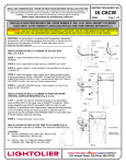
INSTALLATION PROCEDURE FOR: C7CW SERIES 7” DIA. H.I.D. WALL CYLINDER
USED WITH C7E17VM, C7E17OVM, C7P38MH, C7E17PL, C7E17FL SERIES FLANGLESS
REFLECTOR TRIM (ORDER SEPARATELY)
WARNING: USE ONLY REFLECTOR TRIMS PROVIDED BY LIGHTOLIER. USE OF OTHER MANUFACTURERS’
REFLECTOR TRIMS MAY VOID THE UNDERWRITERS LABORATORIES LISTING AND COULD CONSTITUTE A FIRE HAZARD.
CAUTION: For wet locations, in accordance with Underwriters Laboratories
requirements, a line of caulking compound such as acrylic or silicone must be
placed around the perimeter of CANOPY to seal water away from the
outlet box and back openings. Use only compatible REFLECTOR TRIMS
rated for use in Wet Locations.
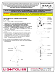
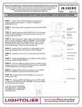
MOUNTING PLATE
CANOPY
GASKET
1/4-20 BOLTS
INSTALLATION OF WALL CYLINDER TO OUTLET BOX
(Fig. 1, 2, 3, & 4)
CLEAT
STEP 1: Attach MOUNTING PLATE to outlet box with OUTLET BOX
MULLION
CLEAT
SCREWS.
OUTLET BOX SCREWS
STEP 2: Pass supply leads through opening in CANOPY and CLEAT.
FIG. 1
FIG. 2
STEP 3: Attach CANOPY and CLEAT to MOUNTING PLATE with (2) ¼-20
BOLTS (provided).
STEP 4: Make Connections. Bare Copper and/or green insulation wire(s)
must be connected to SUPPLY GROUND. Connect WHITE BALLAST LEAD
to NEUTRAL (WHITE) SUPPLY LEAD. Connect BLACK BALLAST LEAD to
HOT SUPPLY LEAD. Use wire nuts (local hardware items).
STEP 5: Install SET SCREWS loosely. Push excess supply leads back into
outlet box. Place cylinder over CLEAT and tighten (2) SET SCREWS.
INSTALLATION OF WALL CYLINDER TO POST OR OTHER
VERTICAL SURFACE MOUNTING (Fig. 2, 3 & 4)
FIG. 3
1. CLEAT can also be mounted directly to any flat surface such as
MULLION. In this case, use of CANOPY is optional. Bring supply
leads through CLEAT and install CLEAT to wall. For wet locations, in
accordance with Underwriters Laboratories requirements, a line of
caulking compound such as acrylic or silicone must be placed around
the perimeter of EXTRUDED ARM to seal water away from the
wireway and back openings.
2. Proceed with Step 4 and 5 above.
INSTALLATION OF REFLECTOR TRIM TO CYLINDER (Fig. 4)
Follow installation instructions in Reflector Trim Instruction Sheet.
CAUTION:
DO NOT ENERGIZE THE LAMP UNTIL
REFLECTOR TRIM IS COMPLETELY INSTALLED.
FIG. 4
A
COMPANY
631 Airport Road, Fall River, MA 02720
READ AND UNDERSTAND THESE INSTRUCTIONS BEFORE INSTALLING FIXTURE
INSTRUCTION SHEET NO.
This fixture is intended for installation in accordance with the National Electrical Code and local regulations. To
assure full compliance with local codes and regulations, check with your local electrical inspector before
installation. To prevent electric shock, turn off electricity at fuse box before proceeding.
IS:C7CW
Retain these instructions for maintenance reference.
A0604
Page 2 of 2
INSTALLATION PROCEDURE FOR: C7CW SERIES 7” DIA. H.I.D. WALL CYLINDER
USED WITH C7E17VM, C7E17OVM, C7P38MH, C7E17PL, C7E17FL SERIES FLANGLESS
REFLECTOR TRIM (ORDER SEPARATELY)
WARNING: USE ONLY REFLECTOR TRIMS PROVIDED BY LIGHTOLIER. USE OF OTHER MANUFACTURERS’
REFLECTOR TRIMS MAY VOID THE UNDERWRITERS LABORATORIES LISTING AND COULD CONSTITUTE A FIRE HAZARD.
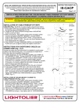
TO REPLACE BALLAST (Fig. 5 & 6)
Before changing the ballast, switch off the main power supply to the fixture.
STEP 1: Remove lamp.
STEP 2: Squeeze LAMPHOLDER SPRING while pushing
upward to disengage from REFLECTOR.
STEP 3: For cylinder with optional Auxiliary lighting, detach AUXILIARY
ASSEMBLY SOCKET ASSEMBLY from REFLECTOR.
STEP 4: Remove WING NUTS, then separate UPPER HOUSING from top
of LOWER HOUSING to access BALLAST/PLATE ASSEMBLY.
STEP 5: Turn SCREW at SUPPORT BRACKET counterclockwise to loosen
SUPPORT BRACKET. Repeat with other (2) screws. Carefully remove
BALLAST/PLATE ASSEMBLY from UPPER HOUSING.
STEP 6: Replace BALLAST, capacitor and ignitor (magnetic type ballast).
STEP 7: Reattach BALLAST/PLATE ASSEMBLY to UPPER HOUSING by
tightening SCREWS until SUPPORT BRACKET locks onto UPPER
HOUSING. Repeat with other (2) screws.
STEP 9: Align STUDS with holes in LOWER HOUSING, then firmly tighten
FIG. 5
with WING NUTS.
STEP 10: Reinstall REFLECTOR. For additional instructions (if needed),
see Reflector Trim Instruction Sheet.
A
COMPANY
631 Airport Road, Fall River, MA 02720