1
1/09/2008
®
VISIT THE LIFETIME WEB SITE:
WWW.LIFETIME.COM
**U.S. Canada and UK customers ONLY**
IF ASSISTANCE IS NEEDED,
DO NOT CONTACT THE STORE!
US and Canada customers call our customer service department at
1 (800) 225-3865
HOURS: 7:00 a.m. to 5:00 p.m. Monday through Friday (Mountain Standard Time)
UK customers call 01992 450333
op
y
**Call, or visit our Web site for Saturday hours**
**For customers outside the U.S., Canada, or UK, please contact the store for
assistance.**
C
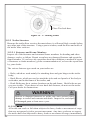
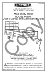
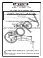
Metal Utility Trailer
MODEL #65004
User’s Manual and Maintenance Guide
Warning: For safe operation of this trailer, be sure to read all
instructions and warnings. Failure to follow instructions and
warnings could result in property damage, serious injury and death.
Instruction #1029777 E
1
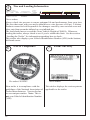
You could win $200!
Register your product at www.lifetime.com and receive three important
EHQH¿WV
1. You automatically will be entered to win $200 in our monthly drawing!
,QWKHXQOLNHO\HYHQWRIDSURGXFWUHFDOORUVDIHW\PRGL¿FDWLRQZHFDQQRWLI\\RX
immediately and directly.
3. You may choose to receive Preferred Customer Announcements and promotions
regarding new Lifetime products.
C
op
y
www.lifetime.com
2
Lifetime Products, inc.
Metal Utility Trailer Model 65004
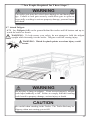
WARNING
This User’s Manual contains safety information and instructions for your trailer. You
must read this manual before loading or towing your trailer. You must follow all safety
precautions and instructions.
Lifetime Products, Inc.
&OHDU¿HOG8WDK
32%R[%OGJ'
3KRQH
1+76$1RWL¿FDWLRQ6WDWHPHQW
If you believe that your vehicle has a defect that could cause a crash or could cause
LQMXU\RUGHDWK\RXVKRXOGLPPHGLDWHO\LQIRUPWKH1DWLRQDO+LJKZD\7UDI¿F6DIHW\
$GPLQLVWUDWLRQ1+76$LQDGGLWLRQWRQRWLI\LQJ/LIHWLPH3URGXFWV
,I1+76$UHFHLYHVVLPLODUFRPSODLQWVLWPD\RSHQDQLQYHVWLJDWLRQDQGLILW¿QGV
that a safety defect exists in a group of vehicles, it may order a recall and remedy
FDPSDLJQ+RZHYHU1+76$FDQQRWEHFRPHLQYROYHGLQLQGLYLGXDOSUREOHPV
between you and Lifetime Products.
7RFRQWDFW1+76$\RXPD\HLWKHUFDOOWKH9HKLFOH6DIHW\+RWOLQHWROOIUHHDW
77<JRWRKWWSZZZVDIHUFDUJRYRUZULWHWR
$GPLQLVWUDWRU1+76$1HZ-HUVH\$YHQXH6(:DVKLQJWRQ'&
You can also obtain other information about motor vehicle safety from http://www.
safercar.gov.
&DOOWRUHDFKRXU&XVWRPHU6HUYLFHOLQH
3
Table of Contents
SECTION 1: SAFETY INFORMATION
SECTION 2: TRAILER PARTS & HARDWARE
SECTION 3: PRE-TAKE-HOME ASSEMBLY
SECTION 4: TRAILER ASSEMBLY
4.1 Secure Tongue
4.2 Attach Rear Floor Extension
4.3 Attach Front Panel
4.4 Attach Side Panels
4.5 Attach Rear Side Extension Panels
4.6 Attach Corner Guards
4.7 Attach Rear Gate
4.8 Attach State License Plate
SECTION 5: TRAILER FEATURES
SECTION 6: COUPLING TO THE TOW VEHICLE
6.1 Using an Adequate Tow Vehicle and Hitch
6.2 Coupling and Uncoupling the Trailer
6.2.1 Trailer with Ball-Hitch Coupler
6.2.1.1 Before coupling the trailer to the tow vehicle
6.2.1.2 Prepare the coupler and hitch
6.2.1.3 Coupling the trailer to the tow vehicle
6.2.1.4 Rigging the safety chains
6.2.1.5 Connecting the electrical cables
6.2.1.6 Uncoupling the Trailer
SECTION 7: TIRE & SAFETY INFORMATION
7.1 Determining Correct Load Limit – Trailer
7.1.1 Trailers 10,000 Pounds GVWR or Less
7.2 Determining Correct Load Limit – Tow Vehicle
7.3 Glossary of Tire Terminology
7.4 Tire Safety - Everything Rides on It
7.4.16DIHW\¿UVW–Basic tire maintenance
7.4.2 Finding your vehicle’s recommended tire pressure and load limits
7.4.3 Understanding tire pressure and load limits
7.4.4 Checking tire pressure
7.4.5 Steps for maintaining proper tire pressure
7.4.6 Tire size
7.4.7 Tire tread
7.4.8 Tire balance and wheel alignment
7.4.9 Tire repair
7.4.10 Tire Fundamentals
7.4.10.1 Information on Passenger Vehicle Tires
7.4.10.2 UTQGS Information
7.4.10.3. Additional Information on Light Truck Tires
7.4.11 Tire Safety Tips
7.4.11.1 Preventing Tire Damage
4
7
11
14
18
18
20
22
24
26
32
33
35
36
40
40
40
40
41
41
41
42
43
44
45
45
45
45
45
48
49
49
49
50
50
50
51
51
51
51
51
53
54
54
54
7.4.11.2 Tire Safety Checklist
7.5 Changing a Flat Tire
7.6 Checking the Tire Pressure
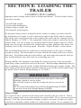
SECTION 8: LOADING THE TRAILER
8.1. Checking the Tongue Weight
8.1.1 Checking Tongue Weight — Using a lever and bathroom scale
8.2 Securing the Cargo
8.2.1 Loading Cargo
8.2.1.1 Preparing the Trailer for Loading
8.2.1.2 Loading the Trailer
SECTION 9: CHECK TRAILER BEFORE & DURING TOWING
SECTION 10: BREAKING IN A NEW TRAILER
SECTION 11: MAINTENANCE
11.1 Inspection, Service & Maintenance Summary Charts
11.2 Inspection and Service Instructions
11.2.1 Axle Bolts, Frame, Suspension, & Structure
11.2.2 Trailer Structure
11.2.2.1 Fasteners and Frame Members
11.2.2.2 Welds
11.2.3 Trailer Connection to Tow Vehicle
11.2.3.1 Coupler and Ball
11.2.4 Landing Leg or Jack
11.2.5 Lights and Signals
11.2.6 Tires
11.2.7 Wheel Rims
11.2.8 Wheels, Bearings and Lug Nuts
11.2.8.1 Unsealed Bearings (Hubs)
11.2.9 Lug Nuts (Bolts)
SECTION 12: WARRANTY INFORMATION
54
54
57
58
60
60
60
60
61
61
63
65
66
66
67
67
68
68
68
69
69
69
69
70
70
70
70
71
75
5
This Page Intentionally Left Blank
6
SECTION 1: SAFETY
INFORMATION
SAFETY ALERT SYMBOLS AND SIGNAL WORDS
The safety information in this
manual is denoted by the safety
alert symbol:
The level of risk is indicated by the following signal words:
SIGNAL WORDS
Warning
Hazards or unsafe practices
which COULD result in severe
personal injury or death if the
warning is ignored.
Hazards or unsafe practices
which could result in minor or
moderate injury if the warning is
ignored.
,IDODEHOEHFRPHVXQUHDGDEOH\RXFDQUHRUGHUWKHPIURP&XVWRPHU
6HUYLFH
Lifetime Products, Inc.
&OHDU¿HOG8WDK
32%R[%OGJ'
or call
3KRQH
Caution
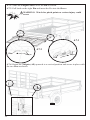
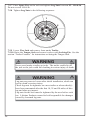
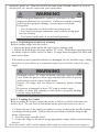
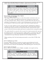
Warning Labels & Locations
2
2
1
6
7
3
5
4
1
7
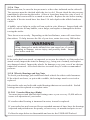
Lug Nuts and Tire Pressure
WARNING
Tire, wheel or lug nut failure can cause loss of control.
Before towing, you must CHECK:
1. Tire pressure and tread.
2. Tires and wheels for damage.
3. Lug nuts for tightness.
For new and remounted wheels,
5HWLJKWHQOXJQXWVDWWKH¿UVW
10, 25 and 50 miles of driving.
ADVERTENCIA
Las fallas en las llantas, ruedas o tuercas a las llantas pueden provocar
pérdida del control. Antes de realizar un acarreo, DEBE REVISAR:
1. Presión y costura de las llantas.
2. Daños en llantas y ruedas.
3. Tuercas a las llantas bien apretadas.
Para llantas nuevas y reacondicionadas, apriete nuevamente las
tuercas a las llantas a los primeros 16 kilómetros, 40,2 kilómetros y 80,5
kilómetros de manejo.
© 2002 NATM
Lug Nuts TIGHT?
Tuercas a las llantas
¿BIEN APRETADAS?
Tires and Wheels OK?
Las llantas y ruedas ¿ESTÁN BIEN?
# 1027939
1
5HRUGHU
7KHSURSHUWLJKWQHVVWRUTXHIRUOXJQXWVLVIWOE'RQRWH[FHHGIWOE
Use a torque wrench to tighten the lug nuts. If you do not have a torque wrench, use
DOXJZUHQFKIURP\RXUWRZYHKLFOHDQGWLJKWHQWKHQXWVDVPXFKDV\RXFDQ7KHQ
KDYHDVHUYLFHJDUDJHRUWUDLOHUGHDOHUWLJKWHQWKHOXJQXWVWRWKHSURSHUWRUTXH6HH
WKHVHFWLRQ³7LUHDQG6DIHW\,QIRUPDWLRQ´IRUPRUHGHWDLOVFRQFHUQLQJWLUHVDIHW\
/XJQXWVDUHDOVRSURQHWRORRVHQDIWHU¿UVWEHLQJDVVHPEOHG:KHQGULYLQJDQHZ
WUDLOHURUDIWHUZKHHOVKDYHEHHQUHPRXQWHGFKHFNWRPDNHVXUHWKH\DUHWLJKWDIWHU
WKH¿UVWDQGPLOHVRIGULYLQJDQGEHIRUHHDFKWRZWKHUHDIWHU
Failure to perform this check can result in a wheel parting from the trailer and a crash,
leading to death or serious injury.
2
Securely Latching the Trailer Gate
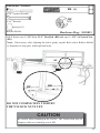
CAUTION
SECURE GATES
BEFORE MOVING
TRAILER
PRECAUCIÓN
¡ASEGURE LOS
PORTONES ANTES
DE MOVER EL
REMOLQUE!
#1027932
5HRUGHU
Ensure latches on trailer gate are secure during towing and when not in use. The trailer
gate must be locked down during use and during storage. Failure to lock gate securely
FRXOG UHVXOW LQ VHULRXV SURSHUW\ GDPDJH SHUVRQDO LQMXU\ DQG GHDWK 6HH WKH VHFWLRQ
³7UDLOHU)HDWXUHV´IRULQIRUPDWLRQUHJDUGLQJODWFKLQJWKHWUDLOHUJDWH
8
3
Coupler, Load Weight and Distribution and Electrical
Connections
WARNING
ADVERTENCIA
Uncoupling will cause trailer to come loose from tow vehicle. You must:
1. CHECK that ball load rating is same or greater than coupler load rating.
2. CHECK that ball size is same as coupler.
3. CLOSE COUPLER CLAMP on ball.
4. LIFT coupler upwards to test that it will not separate from ball.
5. LOCK coupler clamp with pin or padlock.
El desenganche hará que el remolque quede suelto del vehículo remolcador. Usted deberá:
Pin or padlock
1. VERIFICAR que la CAPACIDAD DE CARGA de la bola sea igual o mayor que la
In place
CAPACIDAD DE CARGA del enganche.
Colocar el candado o
2. VERIFICAR que el tamaño de la bola sea igual que el enganche.
gancho
3. CERRAR el TORNILLO DE AJUSTE DEL ENGANCHE sobre la bola.
Lift coupler to check
4. LEVANTAR el enganche para probar que no se separe de la bola.
/HYDQWDUHOHQJDQFKHSDUDYHUL¿FDU 5. CERRAR el tornillo de ajuste del enganche con un gancho o candado.
Open
Abierto
WARNING
Cross chains
Cruzar las cadenas
ADVERTENCIA
WARNING
ADVERTENCIA
WARNING
Improper loading can cause trailer sway and sudden loss of control. You must:
Always use safety chains.
Balance load side to side
Secure load to trailer
DISCONNECTED
Chains hold trailer if connection fails. You must:
Asegurar la carga
Balancear la carga de lado a lado • Ensure weight of load plus trailer weight does not exceed trailer’s capacity
DESCONECTADAS
(GVWR - Gross Vehicle Weight Rating).
1. CROSS chains underneath coupler.
al remolque
• Load heavier items in front of wheels.
2. ALLOW slack for trailer to turn.
• Load evenly side to side.
3. ATTACH chain hooks securely to tow vehicle frame.
Less load in rear
• Secure load to trailer.
Utilice siempre cadenas de seguridad. Las cadenas
Menos carga sobre la Una carga impropia puede causar que el remolque se tambalee o que
sostienen el remolque en caso de que la conexión falle.
parte posterior de las repentinamente pierda el control. Usted deberá:
Enough slack Usted deberá:
• Asegurar que el peso de la carga más el peso del remolque no exceda la
ruedas
1. CRUZAR las cadenas por debajo del enganche.
For turns
capacidad del remolque (Clase de Peso del Vehículo).
6X¿FLHQWHPHQWH 2. PERMITIRTXHODVFDGHQDVTXHGHQÀRMDVSDUDTXH
• Cargar los elementos más pesados en la parte delantera de las ruedas.
More load in front of wheels
ÀRMRSDUDSRGHU el remolque pueda girar.
• Cargar de forma equitativa de lado a lado.
3. SUJETAR de forma segura los ganchos de la
girar
Más carga sobre la parte delantera de las ruedas
• Asegurar la carga al remolque.
#1031540
cadena a los bordes del vehículo remolcador.
Attach hooks to tow vehicle
Sujetar los ganchos al vehículo remolcador
Closed
Cerrado
CONNECTED
CONECTADAS
ADVERTENCIA
Lights can prevent trailer from being hit by other vehicles.
You must:
1. CONNECT trailer and tow vehicle electrical connectors.
2. CHECK all lights: tail lights, turn signals, and brake lights.
3. DO NOT TOW if lights are not working.
Las luces pueden prevenir que otros vehículos choquen el
remolque. Usted deberá:
1. CONECTAR los conectores eléctricos del remolque y del
vehículo remolcador.
2. VERIFICAR todas las luces, las luces traseras, las luces
de guiño, y las luces del freno.
3. NO UTILICE EL REMOLQUE si las luces no funcionan.
5HRUGHU
Loads can suddenly move or topple, which can result in death or serious injury.
Overloaded trailers and improper tongue weight can result in loss of control of the
trailer. Ensure the trailer is coupled correctly and the chains are cross over each other.
(QVXUHWKHORDGLVWLHGVHFXUHO\DQGGRHVQ¶WH[FHHGWKH*URVV9HKLFOH:HLJKW*9:
2000 lb.
(QVXUHWKHHOHFWULFDOFRQQHFWLRQVDUHWLJKWO\¿WWHGDQGIXQFWLRQLQJSURSHUO\$OZD\V
check brake lights and turn signals before each tow.
4
Ball and Hitch Size
5HRUGHU
<RXUQHZWUDLOHUFRPHVZLWKD´FRXSOHU7KHEDOORQWKHWRZYHKLFOHPXVWEH
inches in diameter. An incorrect ball size can cause the separation of the trailer from
the tow vehicle resulting in possible property damage, serious injury and death.
9
5
Tire and Loading Information
MFD BY: LIFETIME PROD. INC.
FABRICADO POR: LIFETIME PROD. INC.
GVWR:
TIRE
RIM (IN)
GAWR
NEUMÁTICO
LLANTA (CM)
COLD INFLATION PRESSURE
PRESIÓN DEL NEUMÁTICO EN FRÍO
PSI (KPA)
DATE/FECHA:
800.225.3865
SGL/DUAL
ÚNICO/DOBLE
SINGLE/ÚNICO
THIS VEHICLE CONFORMS TO ALL APPLICABLE U.S. FEDERAL MOTOR VEHICLE SAFETY STANDARDS (FMVSS) IN
EFFECT ON THE DATE OF MANUFACTURE SHOWN ABOVE.
ESTE VEHÍCULO CUMPLE CON TODAS LAS NORMAS FEDERALES DE SEGURIDAD VIGENTES EFECTIVO EN LA FECHA
DE FABRICACIÓN MOSTRADA ARRIBA.
TYPE OF VEHICULE:
V.I.N/N.I.V.
TIPO DE VEHÍCULO:
TIRE AND LOADING INFORMATION
INFORMACIÓN SOBRE NEUMÁTICOS Y CARGA
El peso del cargamento nunca deberá exceder los
NEUMÁTICO
TAMAÑO
kg.
PRESIÓN DEL NEUMÁTICO EN FRÍO
VEA EL MANUAL DEL USUARIO PARA INFORMACIÓN ADICIONAL
The weight of cargo should never exceed
TIRE
SIZE
lbs.
COLD TIRE PRESSURE
SEE OWNER’S MANUAL FOR ADDITIONAL INFORMATION
# 1027940 B
1RUHRUGHUV
Always check tire pressure to ensure optimum life and performance from your tires.
The tires that came with your trailer should have a tire pressure of 80 psi. Lifetime
Products cannot be held responsible for damages caused by uneven tread wear and
EORZRXWVIURPDQXQGHULQÀDWHGRURYHULQÀDWHGWLUH
7KHORDGVKRXOGQHYHUH[FHHGWKH*URVV9HKLFOH:HLJKWRIOE:KHQHYHU
ORDGLQJWKHWUDLOHUDOZD\VFKHFNWRVHHLI\RX¶UHZLWKLQWKLVOLPLW6HHWKHVHFWLRQ
³/RDGLQJWKH7UDLOHU´IRULQIRUPDWLRQUHJDUGLQJKRZWRFKHFN
7KLVVWLFNHUDOVRGLVSOD\V\RXU9HKLFOH,GHQWL¿FDWLRQ1XPEHU9,1LQWKHERWWRP
OHIWKDQGFRUQHU
6
NATM Compliance
5HRUGHU
Your trailer is in compliance with the
guidelines of the National Association of
Trailer Manufacturers. Your trailer has
its own unique number. Note: This is
not\RXU9HKLFOH,GHQWL¿FDWLRQ1XPEHU
9,1
10
7
Patent Advisory
1RUHRUGHUV
This sticker displays the various patents
applicable to the trailer.
SECTION 2: TRAILER PARTS
& HARDWARE
PARTS LIST
ID
Part #
$$
$%
$,
$&
$'
AE
1013280
AF
1013282
AG
1013252
AH
1013274
AK
1016242
$/
Parts Bag (1024674)
BA
1012273
%*
%,
Hardware Bag (1018013)
%%
%)
Hardware Bag (1018014)
%&
%)
Hardware Bag (1018015)
%(
%)
Hardware Bag (1022647)
%'
%+
%1
Description
7RQJXH´&RXSOHU-DFN$VVHPEO\
5LJKW6LGH3DQHO /HIW6LGH3DQHO
/HIW5HDU6LGH([WHQVLRQ3DQHO
5LJKW5HDU6LGH([WHQVLRQ3DQHO
Front Panel
Tailgate
Trailer Bed
Rear Bed Extension
Cotter Key
´[´+H[%ROW Qty
1
1
1
1
2
Corner Guard
[´6HOI7DSSLQJ6FUHZ
*XDUG5DLO6OHHYH 2
´;´+H[%ROW
´1\ORFN1XW ´;´+H[%ROW
´1\ORFN1XW ´;´+H[%ROW
´1\ORFN1XW ´)ODW:DVKHU ´1\ORFN1XW
TOOLS NEEDED (NOT INCLUDED)
1. Electric Drill
´'ULOO%LW
3. #2 Phillips Bit
6RFNHW:UHQFKZLWK´VKDOORZVRFNHW5HFRPPHQGHGRU´2SHQIDFH
:UHQFKRU$GMXVWDEOH:UHQFK
5XEEHU0DOOHW5HFRPPHQGHGRU+DPPHU
6. Utility Knife
´/XJ:UHQFKRU7LUH,URQ)RUSHULRGLFWLJKWHQLQJRI/XJ1XWV
´:UHQFKRU6RFNHW:UHQFK
´:UHQFKRU6RFNHW:UHQFKZLWK´6RFNHWRU$GMXVWDEOH:UHQFK
11
HARDWARE IDENTIFIER
%HIRUHEHJLQQLQJDVVHPEO\LQYHQWRU\DOOSDUWVXVLQJWKH3DUWV/LVWEHORZDQGWKH
+DUGZDUH,GHQWL¿HUQH[WWZRSDJHV,IDOOSDUWVDUHQRWSUHVHQWGR127DVVHPEOH
the trailer. Call Lifetime Products at the number on the cover of this manual.
Note: The hardware are in clear plastic bags within the plastic bag labeled 1024674
ORFDWHGXQGHUD5HDU6LGH([WHQVLRQ$&RU$'RQWKH7UDLOHUEHG
*Note: Parts are actual size unless noted otherwise.
BE (6)
BC (7)
BB (11)
BF
(24)
*BI
(2)
BG
(4)
*BA
(2)
*AK
(2)
BH (2)
BD (8)
*Not to Scale
12
AL
(2)
*AC (Right)
*AE
*AD (Left)
*AB (Right)
*AI (Left)
*AH
*AF
*AA
*AG
13
SECTION 3:
PRE-TAKE-HOME ASSEMBLY
Hardware Provided:
AK
AL
Not actual size
Not actual size
**At Least 2 Adults Required for the Following Steps**
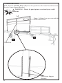
%HIRUHWRZLQJ\RXUWUDLOHUKRPH\RXPXVW¿UVWDVVHPEOHWKHWRQJXH<RXPXVWVOLGH
the tongue out and lock it in place before attaching the trailer to your tow vehicle.
Note: If you’ve already towed your new trailer home, skip to the section “Trailer
$VVHPEO\´WRFRQWLQXH
3.1. Chock the Tires, front and rear, with bricks or wooden blocks.
3.2.:KLOHRQHDGXOWVXSSRUWVWKH7UDLOHUUHPRYHWKHWZRCotter Keys (AK) holding
the 1/2”-13 x 4 1/2” Hex Bolts (AL) and Tongue (AA) in place. Remove the two
Bolts and slide Tongue forward from under Trailer Bed until the holes in the Tongue
are centered with the holes in the Tongue Attachment Plates.
Warning: Do not cut banding around trailer before towing the trailer home. Trailer
parts may fall off causing injury to other motorists.
Warning: Be careful when removing bolts. Tongue could fall
causing serious injury.
AK
AA
AL
Tongue Attachment Plates
AK
AL
Center holes in Tongue with
holes in Attachment Plates.
3.35HLQVHUWBolts and replace the Cotter Keys to secure the Tongue in place.
AK
AK
Use upper hole
AL
AL
Re-insert Cotter Keys
to shaded points as in
illustrations
14
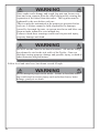
WARNING
Do NOT remove or loosen banding until you’re ready to
assemble the trailer. If you loosen the banding, trailer parts may
dislodge, fall off the trailer during towing and cause an accident.
Failure to follow this warning could result in property damage,
serious injury and death.
Lug Nuts: Tightening Sequence, Torque Requirements
WARNING
Lug nuts are prone to loosen after initial installation possibly causing
the wheel to separate from the trailer leading to property damage, death
or serious injury.
&KHFNOXJQXWVIRUWLJKWQHVVRQDQHZWUDLOHURUZKHQZKHHOVKDYH
EHHQUHPRXQWHGDIWHUWKH¿UVWDQGPLOHVRIGULYLQJDQG
after any impact.
• Lug nuts for the tires must be tightened by the user before each use.
• Lifetime Products cannot be held responsible for damages caused by
loosened lug nuts.
• Before towing the Trailer, you must ensure the lug nuts are tightened to the proper
torque.
• The torque requirements for the Lug Nuts are 95 - 120 ft./lb. Do not exceed 120
ft./lb of torque. Tighten the Lug Nuts in the sequence below before you leave the
dealer.
9HULI\WKHSURSHU36,IRU\RXUWLUH
7LUHSUHVVXUHIRUD´ULPWLUHVKRXOGEHDW80 psi.
1
Tighten lug nuts
in the following
order:
4
3
5
2
15
WARNING
Improper rigging of the safety chains can result in loss of control of
the trailer and the tow vehicle, leading to death or serious injury, if the
trailer uncouples from the tow vehicle.
• Fasten chains to frame of tow vehicle. Do not fasten chain to any
part of the
KLWFKXQOHVVWKHKLWFKKDVKROHVRUORRSVVSHFL¿FDOO\IRUWKDWSXUSRVH
• Cross chains underneath hitch and coupler with enough slack to
permit turning, and to hold tongue up, if the trailer comes loose.
To help ensure your safety as well as other drivers’ safety, you must correctly hitch
\RXUQHZ7UDLOHUWRWKH7RZ9HKLFOH<RXUQHZWUDLOHUFRPHVZLWKD2-inch Coupler.
The tow vehicle must have a 2-inch Ball to match.
&URVVWKHFKDLQVDQGLQVHUWHDFKHQGWKURXJKWKH7RZ9HKLFOH¶VKLWFK&RQQHFWKRRN
WRFKDLQDVLOOXVWUDWHG
Follow local and state laws, but do not exceed 65 mph.
Press down
to lock.
Cross chains over one another
before securing to tow vehicle.
Connecting the Electrical Cables
Connect the trailer lights to the tow vehicle’s electrical system using the electrical
connectors.
• Check all lights for proper operation.
&OHDUDQFHDQG5XQQLQJ/LJKWV7XUQRQWRZYHKLFOHKHDGOLJKWV
%UDNH/LJKWV6WHSRQWRZYHKLFOHEUDNHSHGDO
7XUQ6LJQDOV2SHUDWHWRZYHKLFOHGLUHFWLRQDOVLJQDOOHYHU
%DFNXS/LJKWV3XWWRZYHKLFOHJHDUVKLIWLQWRUHYHUVH
7RHQVXUH\RXUWUDLOHUOLJKWVIXQFWLRQSURSHUO\¿UPO\LQVHUWWKHMale Plug (Trailer)
into the Female Receptor (Tow Vehicle).
From Trailer
16
From Tow Vehicle
From Tow Vehicle
From Trailer
WARNING
Check the connection periodically to ensure tail and break lights
function properly. Failure to follow this warning could result in
property damage, serious personal injury and death.
Note: ,I\RXVWLOOKDYHWKHIRXUZRRGHQEORFNVEROWHGWRWKHIRXUFRUQHUEUDFNHWVRI
WKHWUDLOHUUHPRYHWKHPXVLQJD´ZUHQFK
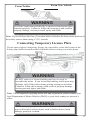
Connecting Temporary License Plate
If your state requires a temporary license on your trailer, secure the license to the
license plate holder located on the left blinker before towing your trailer home.
Temporary
License
WARNING
Do NOT remove or loosen banding until you’re ready to
assemble the trailer. If you loosen the banding, trailer parts may
dislodge, fall off the trailer during towing causing an accident.
Failure to follow this warning could result in property damage,
serious personal injury and death.
Note: For all inquiries regarding trailer title and registration, please contact your
ORFDO'HSDUWPHQWRI0RWRU9HKLFOHV'09RU\RXUORFDOFRXQW\WD[DVVHVVRU¶V
RI¿FH
WARNING
Do not transport people in the trailer. Failure to heed this warn
ing could result in serious injury such as broken bones, brain
damage, paralysis or death.
17
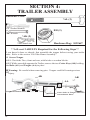
SECTION 4:
TRAILER ASSEMBLY
Hardware Used:
*AL (2)
´6RFNHW:UHQFK
BH (2)
´:UHQFK
*AK (2)
Hardware Bag: 1022647
*Not actual size
**At Least 2 ADULTS Required for the Following Steps**
,I \RX KDYHQ¶W GRQH VR DOUHDG\ ¿UVW DVVHPEOH WKH WRQJXH EHIRUH WRZLQJ \RXU WUDLOHU
home. Refer to the section “PUH7DNH+RPH$VVHPEO\´.
4.1 Secure Tongue
4.1.1 Chock the Tires, front and rear, with bricks or wooden blocks.
4.1.2:KLOHRQHDGXOWVXSSRUWVWKH7UDLOHUUHPRYHWKHWZRCotter Keys (AK) holding
the Bolts (AL) and Tongue (AA) in place.
Warning: Be careful when removing pins. Tongue could fall causing serious
injury.
AK
AK
AA
Tongue Attachment Plates
18
Center holes in Tongue with holes
in Attachment Plates.
4.1.3 Replace the Cotter Keys ZLWKWZR 1/2”-13 Nylock Nuts (BH) to secure the
Tongue in place. Discard Cotter Keys.
BH
BH
Use upper hole
AL
AL
19
Hardware Needed:
BF (3)
´6RFNHW:UHQFK
´:UHQFK
BC (3)
Rubber Mallet
Hardware Bag: 1018014
Utility Knife
**At Least Two ADULTS Required for Assembly**
Before beginning this step, use a Utility Knife to cut the banding around Trailer.
Important: :KLOH DQRWKHU DGXOW SUHYHQWV WKH 5HDU )ORRU ([WHQVLRQ IURP IDOOLQJ
carefully remove all loose parts from the bed of the Trailer. Inventory all parts and
hardware to ensure you received all necessary pieces. The Parts List and Hardware
,GHQWL¿HUDUHORFDWHGRQSDJHV
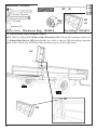
4.2 Attach Rear Floor Extension
4.2.1 Rotate and lower the Tongue Jack into position and chock the Wheels6HHWKH
section “Trailer Features”IRUGHWDLOVRQXVLQJWKH7RQJXH-DFN
4.2.2 Carefully lift the Rear Bed Extension (AH) off the Trailer Bed and attach to
the back of the trailer.
WARNING: Watch for pinch points as serious injury could
occur.
AH
Rear Floor Extension
Be careful not to damage the wiring
insulation (the colored plastic around
WKHZLUHV
7RQJXH-DFN
20
4.2.3:KLOHDQRWKHUDGXOWKROGVWKH5HDU%HG([WHQVLRQLQSODFHVHFXUHWKHRear Bed
Extension to the back of the Trailer BedXVLQJWKUHH3/8”-16 x 2 3/4” Hex Bolts
(BC)DQGWKUHH3/8”-16 Nylock Nuts (BF).
Note: If necessary, after aligning the holes gently tap the Bolt with a Rubber Mallet
or Hammer to help pass the Bolts through the holes.
DO NOT COMPLETELY TIGHTEN
THE NYLOCK NUTS YET.
BC
BF
4.2.46WDUWLQJDWWKH&RXSOHURQWKH7RQJXHJHQWO\SXOOExcess wire from the back of
the Trailer through the center Conduit and into the Tongue.
4.2.5 Tuck any Excess Wire extending out of the Coupler back underneath the
Coupler and into the Tongue.
Coupler
Wiring Housing
Be careful not to damage the
insulation (colored plastic) around
the wires.
21
4.3 Attach Front Panel
4.3.1 6OLGH WKH Front Panel (AE) down between the two front Center Support
Brackets of the Trailer Bed.
WARNING: Watch for pinch points as serious
injury could occur.
Center Support
AE
Center Support Brackets
22
Hardware Needed:
BB (1)
´6RFNHW:UHQFK
BF
(1)
´:UHQFK
Rubber Mallet
Hardware Bag: 1018013
4.3.2,QVHUWRQH3/8”-16 x 2 1/2” Hex Bolt (BB)DQGRQH3/8”-16 Nylock Nut
(BF).
Note: If necessary, after aligning the holes gently tap the Bolt with a Rubber Mallet
or Hammer to help pass it through the holes.
BF
BF
BB
BB
DO NOT COMPLETELY TIGHTEN
THE NYLOCK NUTS YET.
CAUTION
Be careful when standing in the Trailer. The Trailer Bed may be
slippery when wet causing you to fall.
23
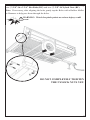
4.4 Attach Side Panels
4.4.16OLGHWKHLeft Side Panel (AI)GRZQLQWRSRVLWLRQVRWKH&HQWHU3RVW¿WVEHWZHHQ
WKHVLGH&HQWHU6XSSRUW%UDFNHWV
WARNING: Watch for pinch points as serious injury could
occur.
AI
Note: Lifetime logo goes towards the
front of the Trailer.
Center Post
6LGH&HQWHU6XSSRUW
Brackets
24
Hardware Needed:
BB (4)
´6RFNHW:UHQFK
BF (4)
´:UHQFK
Hardware Bag: 1018013
Rubber Mallet
BF
(6)
BD (6)
Hardware Bag: 1022647
BE (6)
Hardware Bag: 1018015
4.4.26WDUWLQJDWWKHERWWRPKROHVHFXUHWKH6LGH3DQHOWRWKH)URQW3DQHOXVLQJWKUHH
3/8”-16 x 3 3/4” Hex Bolts (BE)WKUHH3/8” Flat Washers (BD)DQGWKUHH
3/8”-16 Nylock Nuts (BF).
4.4.36WDUWLQJDWWKHERWWRPKROHVHFXUHWKH6LGH3DQHOWRWKH6LGH&HQWHU6XSSRUW
%UDFNHWVXVLQJWZR3/8”-16 x 2 1/2” Hex Bolts (BB)DQGWZR3/8”-16 Nylock
Nuts (BF).
4.4.4 Repeat steps 4.4.1 - 4.4.3IRUWKHRWKHU6LGH3DQHO
Note: If necessary, after aligning the holes gently tap the Bolts with a Rubber Mallet
or Hammer to help pass them through the holes.
BF
BF
BB
BE
BD
DO NOT
COMPLETELY
TIGHTEN THE
NYLOCK NUTS YET.
25
Hardware Needed:
BC (2)
´6RFNHW:UHQFK
Rubber Mallet
BI
(2)
BF
(2)
´:UHQFK
Hardware Bag: 1018014
Parts Bag: 1024674
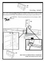
4.5 Attach Rear Side Extension Panels
4.5.1:KLOHVOLGLQJWKHLeft Rear Side Extension (AC) down into position, insert one
Guard Rail Sleeve (BI)EHWZHHQWKHWZRUDLOVDVVKRZQ:KHQORRNLQJIURPWKH
EDFNRIWKH7UDLOHUWKH/HIW5HDU6LGH([WHQVLRQJRHVRQWKHULJKWVLGH
AC
BI
BI
26
4.5.26HFXUHWKHLeft Rear Side Extension Panel (AB) to the Bed Extension using
WZR3/8”-16 x 2 3/4” Hex Bolts (BC)DQGWZR3/8”-16 Nylock Nuts (BF).
Note: If necessary, after aligning the holes gently tap the Bolts with a Rubber Mallet
or Hammer to help pass them through the holes.
WARNING: Watch for pinch points as serious injury could
occur.
BC
BF
DO NOT COMPLETELY TIGHTEN
THE NYLOCK NUTS YET.
27
Hardware Needed:
BB (3)
´6RFNHW:UHQFK
BF
(3)
´:UHQFK
BD (1)
Rubber Mallet
Hardware Bag: 1018013
Hardware Bag: 1022647
4.5.36WDUWLQJDWWKHERWWRPKROHVHFXUHWKH/HIW5HDU6LGH([WHQVLRQWRWKH6LGH3DQHO
DQG5HDU6LGH%UDFNHWXVLQJWKUHH3/8”-16 x 2 1/2” Hex Bolts (BB)RQH3/8”
Flat Washer (BD)DQGWKUHH3/8”-16 Nylock Nuts (BF).
Note: If necessary, after aligning the holes gently tap the Bolts with a Rubber Mallet
or Hammer to help pass them through the holes.
WARNING: Watch for pinch points as serious injury could
occur.
BB
BF
BD
DO NOT COMPLETELY TIGHTEN
THE NYLOCK NUTS YET.
28
Hardware Needed:
BI
(2)
Parts Bag: 1024674
4.5.4:KLOHVOLGLQJWKHRight Rear Side Extension Panel (AD) down into position,
LQVHUWRQHGuard Rail Sleeve (BI)EHWZHHQWKHWZRUDLOVDVVKRZQ:KHQORRNLQJ
IURPWKHEDFNRIWKH7UDLOHUWKH5LJKW5HDU6LGH([WHQVLRQJRHVRQWKHOHIWVLGH
WARNING: Watch for pinch points as serious injury could
occur.
AD
BI
BI
DO NOT COMPLETELY TIGHTEN
THE NYLOCK NUTS YET.
29
Hardware Needed:
BC (2)
´6RFNHW:UHQFK
´:UHQFK
BF
(2)
Rubber Mallet
Hardware Bag: 1018014
4.5.56HFXUHWKH5LJKW5HDU6LGH([WHQVLRQ3DQHO$%WRWKH%HG([WHQVLRQXVLQJ
WZR3/8”-16 x 2 3/4” Hex Bolts (BC)DQGWZR3/8”-16 Nylock Nuts (BF).
Note: If necessary, after aligning the holes gently tap the Bolts with a Rubber Mallet
or Hammer to help pass them through the holes.
WARNING: Watch for pinch points as serious injury could
occur.
BC
BF
30
Hardware Needed:
BB (3)
´6RFNHW:UHQFK
BF
(3)
´:UHQFK
BD (1)
Rubber Mallet
Hardware Bag: 1022647
Hardware Bag: 1018013
4.5.66WDUWLQJDWWKHERWWRPKROHVHFXUHWKH5LJKW5HDU6LGH([WHQVLRQ3DQHOWRWKH
6LGH3DQHODQG5HDU6LGH3DQHO%UDFNHWXVLQJWKUHH3/8”-16 x 2 1/2” Hex Bolts
(BB)RQH3/8” Flat Washer (BD) DQGWKUHH3/8”-16 Nylock Nuts (BF).
Note: If necessary, after aligning the holes gently tap the Bolts with a Rubber Mallet
or Hammer to help pass them through the holes.
4.5.7 Tighten all hardware from steps 4.2.3 - 4.5.6, but do not overtighten.
BD
BB
BF
BD
Remember: Tighten all hardware
before proceeding to the next step,
but do not overtighten.
31
Hardware Needed:
BA
(2)
Not actual size
BG (4)
Hardware Bag: 1018016
4.6 Attach Corner Guards
Important: If you have not tightened all hardware, do so before beginning this step,
but do not overtighten.
4.6.1 6HW WKH Corner Guard (BA) in place on the corner of the Front and Side
Panels. Drill an 1/8” Pilot hole through the holes in the Corner Guard and into the
Panels.
4.6.2 Fasten a Corner Guard (BA) to the front left and right corners of the pan
HOV ZLWK WZR #10 x 3/4” Self-Tapping Screws (BG). Repeat for other Corner
Guard.
WARNING: Watch for pinch points as serious injury could
occur.
BA
BG
BG
Lip
Corner Guard
Note: 6HW WKH OLS RI WKH &RUQHU *XDUG
over the top edges of the Panels.
32
**Two People Required for These Steps**
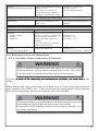
WARNING
The trailer gate must be locked down during use and during stor
age. Failure to lock gate securely could allow gate to open un
expectedly resulting in serious property damage, personal injury
and death.
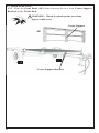
4.7 Attach Tailgate
4.7.1 Lay Tailgate (AF) on the ground behind the trailer and lift bottom end up to
wards the trailer as shown.
WARNING: To help ensure your safety, do not attempt to hold the tailgate
upright while fastening it to the trailer. Tailgate could fall causing injury.
WARNING: Watch for pinch points as serious injury could
occur.
AF
WARNING
Do not play or hang on tailgate. If not secured properly, tailgate
could open suddenly or fall. Failure to comply with this warning
could result in property damage, serious injury or death.
CAUTION
Be careful when standing in the Trailer. The Trailer Bed may be
slippery when wet causing you to fall.
33
4.7.26OLGHWKHTailgate Sleeve over the Pin as shown.
4.7.3 Pull back on the right Pin and insert the Pin into the Sleeve.
WARNING: Watch for pinch points as serious injury could
occur.
4.7.3
4.7.2
Pin
Sleeve
Sleeve
Pin
4.7.4 Rotate the Tailgate (AF) upwards to a vertical position and secure in place with
the two Pins as shown.
34
4.8 Attach State License Plate
4.8.1 If your state requires a license plate on your trailer, bolt the license plate to the
license plate holder located below the left blinker.
67$7(
/,&(16(
Note: For all inquiries regarding trailer title and registration, please contact your
ORFDO'HSDUWPHQWRI0RWRU9HKLFOHV'09RU\RXUORFDOFRXQW\WD[DVVHVVRU¶V
RI¿FH
WARNING
'R127XVHWKH*DWHIRUWLHGRZQORFDWLRQV$OODUWLFOHVEHLQJ
towed must be tied to the side walls of the Trailer. Gate can
dislodge causing property damage and possible injury or death to
other motorists and pedestrians.
Follow local and state laws, but do not exceed 65 mph.
WARNING
Do not transport people in the trailer. Failure to heed this warn
ing could result in serious injury such as broken bones, brain
damage, paralysis or death.
35
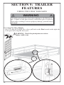
SECTION 5: TRAILER
FEATURES
86,1*7:2:$<7$,/*$7(
WARNING
The trailer gate must be locked down during use and during stor
age. Failure to lock gate securely could allow gate to open un
expectedly resulting in serious property damage, personal injury
and death.
5.1 Using Two-Way Tailgate
5.1.1 To open the Tailgate like a door, pull back on the Pins located on the right side
of the gate and swing the door open.
WARNING: Watch for pinch points as serious
injury could occur.
36
5.2 To lower the tailgate to a ramp position, pull up on the upper Pins located on both
WKHOHIWDQGULJKWKDQGVLGHVRIWKHWDLOJDWH
WARNING: Watch for pinch points as
serious injury could occur.
WARNING
Do not play or hang on tailgate. If not secured properly, tailgate
could open suddenly or fall. Failure to comply with this warning
could result in property damage, serious injury or death.
WARNING
'R127XVHWKH*DWHIRUWLHGRZQORFDWLRQV$OODUWLFOHVEHLQJ
towed must be tied to the side walls of the Trailer. Gate can
dislodge causing property damage and possible injury or death to
other motorists and pedestrians.
37
86,1*7+(721*8(-$&.
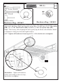
5.3 USING THE TONGUE JACK
5.3.1 Pull the Locking PinRXWWRUHOHDVHWKH7RQJXH-DFN
Locking Pin
5.3.2 Rotate Tongue Jack down to a vertical position and lock into place with Locking Pin.
Locking Pin
38
5.3.3 Rotate Jack HandleFORFNZLVHWROLIW7RQJXHFRXQWHUFORFNZLVHWRORZHUWKH
Tongue.
WARNING
%HIRUHWRZLQJDOZD\VURWDWH7RQJXH-DFNWRXSZDUG
KRUL]RQWDO SRVLWLRQ DQG VHFXUH ZLWK /RFNLQJ 3LQ
)DLOXUH WR GR VR FRXOG GDPDJH 7RQJXH -DFN ZKLOH
WRZLQJUHQGHULQJ7RQJXH-DFNLQRSHUDEOH
39
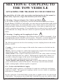
SECTION 6: COUPLING TO
THE TOW VEHICLE
ATTACHING THE TRAILER TO YOUR VEHICLE
You must follow all of the safety precautions and instructions in this manual to
ensure safety of persons, cargo, and satisfactory life of the trailer.
6.1 Warning: Using an Adequate Tow Vehicle and Hitch
,IWKHYHKLFOHRUKLWFKLVQRWSURSHUO\VHOHFWHGDQGPDWFKHGWRWKH*URVV9HKLFOH
:HLJKW5DWLQJ*9:5RI\RXUWUDLOHU\RXFDQFDXVHDQDFFLGHQWWKDWFRXOGOHDGWR
death or serious injury. If you already have a tow vehicle, know your vehicle tow
rating and make certain the trailer’s rated capacity is less than or equal to the tow
YHKLFOH¶VUDWHGWRZLQJFDSDFLW\,I\RXDOUHDG\KDYHRUSODQWREX\DWUDLOHUPDNH
certain that the tow rating of the tow vehicle is equal to or greater than that of the
trailer.
6.2 Warning: Coupling and Uncoupling the Trailer
$VHFXUHFRXSOLQJRUIDVWHQLQJRIWKHWUDLOHUWRWKHWRZYHKLFOHLVHVVHQWLDO$ORVV
of coupling may result in death or serious injury. Therefore, you must understand
and follow all of the instructions for coupling your trailer to your tow vehicle.
The following parts are involved in ensuring a secure coupling between the trailer
and tow vehicle:
Coupler: A device on the tongue of the trailer that connects to the hitch on the
tow vehicle.
Hitch: A device on the tow vehicle that supports the weight of the trailer tongue
and pulls the trailer. The coupler attaches to the hitch.
Safety chains: If the coupler connection comes loose, the safety chains can keep
WKHWUDLOHUDWWDFKHGWRWKHWRZYHKLFOH:LWKSURSHUO\ULJJHGVDIHW\FKDLQVLWLV
possible to keep the tongue of the trailer from digging into the road pavement,
HYHQLIWKHFRXSOHUWRKLWFKFRQQHFWLRQFRPHVDSDUW
Trailer lighting (and braking) connector: A device that connects electrical
power from the tow vehicle to the trailer. Electricity is used to turn on brake
lights, running lights, and turn signals as required.
6.2.1 Trailer with Ball-Hitch Coupler
A ball hitch coupler connects to a ball that is located on or under the rear bumper
of the tow vehicle. This system of coupling a trailer to a tow vehicle is sometimes
UHIHUUHGWRDV³EXPSHUSXOO´
40
:HKDYHXWLOL]HGDLQFK%DOO+LWFKFRXSOHUWKDWLVVXLWDEOHIRUWKHVL]HDQGZHLJKW
RIWKHWUDLOHU<RXPXVWSURYLGHDKLWFKDQGLQFKEDOOIRU\RXUWRZYHKLFOHZKHUH
the load rating of the hitch and ball is equal to or greater than that of your trailer.
Also, the ball size must be the same as the coupler size. If the hitch ball is too
small, too large, is underrated, is loose or is worn, the trailer can come loose from
the tow vehicle, and may cause death or serious injury.
7+(72:9(+,&/(+,7&+$1'%$//0867+$9($5$7('72:,1*
CAPACITY EQUAL TO OR GREATER THAN THE TRAILER *5266
9(+,&/(:(,*+75$7,1**9:5
,7,6(66(17,$/7+$77+(+,7&+%$//%(2)7+(6$0(6,=($67+(
&283/(5,1&+(6
7KHEDOOVL]HDQGORDGUDWLQJFDSDFLW\DUHPDUNHGRQWKHEDOOKLWFKFDSDFLW\LV
marked on the hitch.
6.2.1.1 Before coupling the trailer to the tow vehicle
(QVXUHWKHVL]HDQGUDWLQJRIKLWFKEDOOPDWFKWKHLQFKFRXSOHURQ\RXUWUDLOHU
Hitch balls and couplers are marked with their size and rating.
:LSHWKHKLWFKEDOOFOHDQLQVSHFWLWYLVXDOO\DQGIHHOIRUÀDWVSRWVFUDFNVDQG
pits.
• Rock the ball to make sure it is tight to the hitch, and visually check that the
hitch ball nut is solid against the lock washer and hitch frame.
:LSHWKHLQVLGHDQGRXWVLGHRIWKHFRXSOHUFOHDQDQGLQVSHFWLWYLVXDOO\IRUFUDFNV
DQGGHIRUPDWLRQVIHHOWKHLQVLGHRIWKHFRXSOHUIRUZRUQVSRWVDQGSLWV
• Be sure the coupler is tight to the tongue of the trailer. All coupler fasteners
must be visibly solid against the trailer frame.
• Raise the bottom surface of the coupler above the top of the hitch ball. Use
wood or concrete blocks to support the trailer tongue.
6.2.1.2 Preparing the coupler and hitch
• Lubricate the hitch ball and the inside of the coupler with a thin layer of
automotive bearing grease.
• Open the coupler locking mechanism. Ball couplers have a locking mechanism
with an internal moving piece and an outside handle.
In the open position, the coupler is able to drop fully onto the hitch ball.
6HHWKHFRXSOHULQVWUXFWLRQVIRUGHWDLOVRISODFLQJWKHFRXSOHULQWKH³RSHQ´
position.
6ORZO\EDFNXSWKHWRZYHKLFOHVRWKDWWKHKLWFKEDOOLVQHDURUDOLJQHGXQGHUWKH
coupler.
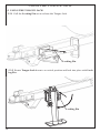
6.2.1.3 Coupling the trailer to the tow vehicle
Lift the coupler and place it over the ball.
• Lower the trailer until the coupler fully engages the hitch ball. If the coupler
does not line up with the hitch ball, adjust the position of the tow vehicle.
• Engage the coupler locking mechanism. In the engaged position, the locking
mechanism securely holds the coupler to the hitch ball.
41
• Insert a pin or lock through the hole in the locking mechanism.
• Be sure the coupler is all the way on the hitch ball and the locking mechanism is
engaged.
If the coupler cannot be secured to the hitch ball, do not tow the trailer.
Call Lifetime Products at 1-800-225-3865 or your dealer for assistance.
• Lower the trailer so that its entire tongue weight is held by the hitch. Push the
safety latch downward to a horizontal position to lock it in place.
WARNING
8VH:0RWRU2LOWROXEULFDWHWKHEDOODQGLQVLGHRIFRXSOHU
Always check ball and coupler before each tow for damaged or
worn edges. Damaged balls and couplers should be replaced
immediately. Failure to follow this warning could result in
property damage, personal injury and death.
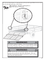
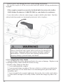
6.2.1.4 Rigging the safety chains
9LVXDOO\LQVSHFWWKHVDIHW\FKDLQVDQGKRRNVIRUZHDURUGDPDJH5HSODFHZRUQ
or damaged safety chains and hooks before towing.
• Rig the safety chains so that they:
FURVVXQGHUQHDWKWKHFRXSOHU
2. loop around a frame member of the tow vehicle or to holes provided in the
hitch system (but, do not attach them to an interchangeable part of the hitch
DVVHPEO\DQG
3. have enough slack to permit tight turns, but not be close to the road surface,
so if the trailer uncouples, the safety chains can hold the tongue up above the
road.
42
WARNING
Improper rigging of the safety chains can result in loss of control
of the trailer and the tow vehicle, leading to death or serious
injury, if the trailer uncouples from the tow vehicle.
• Fasten chains to frame of tow vehicle. Do not fasten chains
to any part of the hitch unless the hitch has holes or loops
VSHFL¿FDOO\IRUWKDWSXUSRVH
• Cross chains underneath hitch and coupler with enough slack
to permit turning, and to hold tongue up, if the trailer comes
loose.
6.2.1.5 Connecting the electrical cables
Connect the trailer lights to the tow vehicle’s electrical system using the electrical
connectors.
• Check all lights for proper operation.
&OHDUDQFHDQG5XQQLQJ/LJKWV7XUQRQWRZYHKLFOHKHDGOLJKWV
%UDNH/LJKWV6WHSRQWRZYHKLFOHEUDNHSHGDO
7XUQ6LJQDOV2SHUDWHWRZYHKLFOHGLUHFWLRQDOVLJQDOOHYHU
%DFNXS/LJKWV3XWWRZYHKLFOHJHDUVKLIWLQWRUHYHUVH
Warning:7RHQVXUH\RXUWUDLOHUOLJKWVIXQFWLRQSURSHUO\¿UPO\LQVHUWWKH
Male Plug (Trailer) into the Female Receptor (Tow Vehicle).
43
From Trailer
From Trailer
From Tow Vehicle
From Tow Vehicle
WARNING
Check the connection periodically to ensure tail and break lights
function properly. Failure to follow this warning could result in
property damage, personal injury and death.
6.2.1.6 Uncoupling the Trailer
Follow these steps to uncouple your ball hitch trailer from the tow vehicle:
1. Block trailer tires to prevent the trailer from rolling.
2. Place wood or concrete blocks under the coupler for support.
3. Disconnect the electrical connector.
4. Disconnect the safety chains from the tow vehicle.
5. Unlock the coupler and pull the safety latch upward to a vertical position and
use a jack to lift the trailer off the ball.
Unlock
44
SECTION 7: TIRE & SAFETY
INFORMATION
CHECKING & CHANGING TIRES
7.1 Determining Correct Load Limit – Trailer
7.1.1 Trailers 10,000 Pounds GVWR or Less
/RFDWHWKHVWDWHPHQW³7KHZHLJKWRIFDUJRVKRXOGQHYHUH[FHHG;;;NJRU
;;;OE´RQ\RXUYHKLFOH¶VSODFDUG
7KLV¿JXUHHTXDOVWKHDYDLODEOHDPRXQWRIFDUJRDQGOXJJDJHORDGFDSDFLW\
3. Determine the combined weight of luggage and cargo being loaded on the
vehicle. That weight may not safely exceed the available cargo and luggage load
capacity.
The trailer’s placard refers to the Tire Information Placard attached adjacent to or
QHDUWKHWUDLOHU¶V9,1&HUWL¿FDWLRQODEHODWWKHOHIWIURQWRIWKHWUDLOHU
7.2 Determining Correct Load Limit – Tow Vehicle
1. Locate the statement, “The combined weight of occupants and cargo should
QHYHUH[FHHG;;;OE´RQ\RXUYHKLFOH¶VSODFDUG
2. Determine the combined weight of the driver and passengers who will be riding
in your vehicle.
6XEWUDFWWKHFRPELQHGZHLJKWRIWKHGULYHUDQGSDVVHQJHUVIURP;;;NLORJUDPV
RU;;;SRXQGV
7KHUHVXOWLQJ¿JXUHHTXDOVWKHDYDLODEOHDPRXQWRIFDUJRDQGOXJJDJHFDSDFLW\
)RUH[DPSOHLIWKH³;;;´DPRXQWHTXDOVOEDQGWKHUHZLOOEH¿YHOE
passengers in your vehicle, the amount of available cargo and luggage capacity is
OE[ OE
5. Determine the combined weight of luggage and cargo being loaded on the
vehicle. That weight may not safely exceed the available cargo and luggage capacity
FDOFXODWHGLQ6WHS
6. If your vehicle will be towing a trailer, load from your trailer will be transferred
to your vehicle. Consult the tow vehicle’s manual to determine how this weight
transfer reduces the available cargo and luggage capacity of your vehicle.
7.3 Glossary of Terminology
Accessory weight: The combined weight (in excess of those standard items which
PD\EHUHSODFHGRIDXWRPDWLFWUDQVPLVVLRQSRZHUVWHHULQJSRZHUEUDNHVSRZHU
windows, power seats, radio and heater, to the extent that these items are available
DVIDFWRU\LQVWDOOHGHTXLSPHQWZKHWKHULQVWDOOHGRUQRW
Bead: The part of the tire that is made of steel wires, wrapped or reinforced by ply
FRUGVDQGWKDWLVVKDSHGWR¿WWKHULP
Bead separation: This is the breakdown of the bond between components in the
bead.
Bias ply tire: A pneumatic tire in which the ply cords that extend to the beads are
laid at alternate angles substantially less than 90 degrees to the center line of the
tread.
45
Carcass: 7KHWLUHVWUXFWXUHH[FHSWWUHDGDQGVLGHZDOOUXEEHUZKLFKZKHQLQÀDWHG
bears the load.
Chunking: The breaking away of pieces of the tread or sidewall.
&ROGLQÀDWLRQSUHVVXUHThe pressure in the tire before you drive.
Cord: The strands forming the plies in the tire.
Cord separation: The parting of cords from adjacent rubber compounds.
Cracking: Any parting within the tread, sidewall, or inner liner of the tire
extending to cord material.
CT:$SQHXPDWLFWLUHZLWKDQLQYHUWHGÀDQJHWLUHDQGULPV\VWHPLQZKLFKWKHULP
LVGHVLJQHGZLWKULPÀDQJHVSRLQWHGUDGLDOO\LQZDUGDQGWKHWLUHLVGHVLJQHGWR¿W
RQWKHXQGHUVLGHRIWKHULPLQDPDQQHUWKDWHQFORVHVWKHULPÀDQJHVLQVLGHWKHDLU
cavity of the tire.
Curb weight: The weight of a motor vehicle with standard equipment including
the maximum capacity of fuel, oil, and coolant, and, if so equipped, air conditioning
and additional weight optional engine.
Extra load tire: $WLUHGHVLJQHGWRRSHUDWHDWKLJKHUORDGVDQGDWKLJKHULQÀDWLRQ
pressures than the corresponding standard tire.
Groove: The space between two adjacent tread ribs.
Inner liner:7KHOD\HUVIRUPLQJWKHLQVLGHVXUIDFHRIDWXEHOHVVWLUHWKDWFRQWDLQV
WKHLQÀDWLQJPHGLXPZLWKLQWKHWLUH
Inner-liner separation: The parting of the inner liner from cord material in the
carcass.
,QWHQGHGRXWERDUGVLGHZDOO7KHVLGHZDOOWKDWFRQWDLQVDZKLWHZDOOEHDUVZKLWH
lettering or bears manufacturer, brand, and/or model name molding that is higher or
deeper than the same molding on the other sidewall of the tire or the outward facing
sidewall of an asymmetrical tire that has a particular side that must always face
outward when mounted on a vehicle.
Light truck (LT) tire: A tire designated by its manufacturer as primarily intended
for use on lightweight trucks or multipurpose passenger vehicles.
Load rating:7KHPD[LPXPORDGWKDWDWLUHLVUDWHGWRFDUU\IRUDJLYHQLQÀDWLRQ
pressure.
Maximum load rating: The load rating for a tire at the maximum permissible
LQÀDWLRQSUHVVXUHIRUWKDWWLUH
0D[LPXPSHUPLVVLEOHLQÀDWLRQSUHVVXUH7KHPD[LPXPFROGLQÀDWLRQSUHVVXUH
WRZKLFKDWLUHPD\EHLQÀDWHG
Maximum loaded vehicle weight: The sum of curb weight, accessory weight,
vehicle capacity weight, and production options weight.
Measuring rim:7KHULPRQZKLFKDWLUHLV¿WWHGIRUSK\VLFDOGLPHQVLRQ
requirements.
Non-pneumatic rim:$PHFKDQLFDOGHYLFHZKLFKZKHQDQRQSQHXPDWLFWLUH
assembly incorporates a wheel, supports the tire, and attaches, either integrally or
separably, to the wheel center member and upon which the tire is attached.
Non-pneumatic spare tire assembly:$QRQSQHXPDWLFWLUHDVVHPEO\LQWHQGHG
IRUWHPSRUDU\XVHLQSODFHRIRQHRIWKHSQHXPDWLFWLUHVDQGULPVWKDWDUH¿WWHGWRD
passenger car in compliance with the requirements of this standard.
Non-pneumatic tire: A mechanical device which transmits, either directly or
through a wheel or wheel center member, the vertical load and tractive forces from
46
the roadway to the vehicle, generates the tractive forces that provide the directional
FRQWURORIWKHYHKLFOHDQGGRHVQRWUHO\RQWKHFRQWDLQPHQWRIDQ\JDVRUÀXLGIRU
providing those functions.
Non-pneumatic tire assembly:$QRQSQHXPDWLFWLUHDORQHRULQFRPELQDWLRQZLWK
a wheel or wheel center member, which can be mounted on a vehicle.
Normal occupant weight:7KLVPHDQVNLORJUDPVOEWLPHVWKHQXPEHURI
RFFXSDQWVVSHFL¿HGLQWKHVHFRQGFROXPQRI7DEOH,RI&)5
Occupant distribution:7KHGLVWULEXWLRQRIRFFXSDQWVLQDYHKLFOHDVVSHFL¿HGLQ
the third column of Table I of 49 CFR 571.110.
Open splice: Any parting at any junction of tread, sidewall, or inner liner that
extends to cord material.
Outer diameter:7KHRYHUDOOGLDPHWHURIDQLQÀDWHGQHZWLUH
Overall width: The linear distance between the exteriors of the sidewalls of an
LQÀDWHGWLUHLQFOXGLQJHOHYDWLRQVGXHWRODEHOLQJGHFRUDWLRQVRUSURWHFWLYHEDQGVRU
ribs.
Ply:$OD\HURIUXEEHUFRDWHGSDUDOOHOFRUGV
Ply separation: A parting of rubber compound between adjacent plies.
Pneumatic tire: A mechanical device made of rubber, chemicals, fabric and
steel or other materials, that, when mounted on an automotive wheel, provides the
WUDFWLRQDQGFRQWDLQVWKHJDVRUÀXLGWKDWVXVWDLQVWKHORDG
Production options weight: The combined weight of those installed regular
SURGXFWLRQRSWLRQVZHLJKLQJRYHUNLORJUDPVOELQH[FHVVRIWKRVHVWDQGDUG
items which they replace, not previously considered in curb weight or accessory
weight, including heavy duty brakes, ride levelers, roof rack, heavy duty battery,
and special trim.
Radial ply tire: A pneumatic tire in which the ply cords that extend to the beads
are laid at substantially 90 degrees to the center line of the tread.
5HFRPPHQGHGLQÀDWLRQSUHVVXUH7KLVLVWKHLQÀDWLRQSUHVVXUHSURYLGHGE\WKH
YHKLFOHPDQXIDFWXUHURQWKH7LUH,QIRUPDWLRQODEHODQGRQWKH&HUWL¿FDWLRQ9,1
tag.
Reinforced tire:$WLUHGHVLJQHGWRRSHUDWHDWKLJKHUORDGVDQGDWKLJKHULQÀDWLRQ
pressures than the corresponding standard tire.
Rim: A metal support for a tire or a tire and tube assembly upon which the tire
beads are seated.
Rim diameter: This means the nominal diameter of the bead seat.
Rim size designation: This means the rim diameter and width.
Rim type designation: This means the industry of manufacturer’s designation for
a rim by style or code.
Rim width: 7KLVPHDQVWKHQRPLQDOGLVWDQFHEHWZHHQULPÀDQJHV
Section width: The linear distance between the exteriors of the sidewalls of an
LQÀDWHGWLUHH[FOXGLQJHOHYDWLRQVGXHWRODEHOLQJGHFRUDWLRQRUSURWHFWLYHEDQGV
Sidewall: That portion of a tire between the tread and bead.
Sidewall separation: The parting of the rubber compound from the cord material
in the sidewall.
Special Trailer (ST) tire:7KH³67´LVDQLQGLFDWLRQWKHWLUHLVIRUWUDLOHUXVHRQO\
Test rim:7KHULPRQZKLFKDWLUHLV¿WWHGIRUWHVWLQJDQGPD\EHDQ\ULPOLVWHGDV
47
appropriate for use with that tire.
Tread: That portion of a tire that comes into contact with the road.
Tread rib: A tread section running circumferentially around a tire.
Tread separation: Pulling away of the tread from the tire carcass.
Tread-wear indicators (TWI): The projections within the principal grooves
designed to give a visual indication of the degrees of wear of the tread.
Vehicle capacity weight: The rated cargo and luggage load plus 68 kilograms (150
OEWLPHVWKHYHKLFOH¶VGHVLJQDWHGVHDWLQJFDSDFLW\
Vehicle maximum load on the tire: The load on an individual tire that is
determined by distributing to each axle its share of the maximum loaded vehicle
weight and dividing by two.
Vehicle normal load on the tire: The load on an individual tire that is determined
by distributing to each axle its share of the curb weight, accessory weight, and
QRUPDORFFXSDQWZHLJKWGLVWULEXWHGLQDFFRUGDQFHZLWK7DEOH,RI&5)
and dividing by 2.
Weather side: 7KHVXUIDFHDUHDRIWKHULPQRWFRYHUHGE\WKHLQÀDWHGWLUH
Wheel center member: ,QWKHFDVHRIDQRQSQHXPDWLFWLUHDVVHPEO\LQFRUSRUDWLQJ
a wheel, a mechanical device which attaches, either integrally or separably, to the
QRQSQHXPDWLFULPDQGSURYLGHVWKHFRQQHFWLRQEHWZHHQWKHQRQSQHXPDWLFULP
DQGWKHYHKLFOHRULQWKHFDVHRIDQRQSQHXPDWLFWLUHDVVHPEO\QRWLQFRUSRUDWLQJ
a wheel, a mechanical device which attaches, either integrally or separably, to the
QRQSQHXPDWLFWLUHDQGSURYLGHVWKHFRQQHFWLRQEHWZHHQWLUHDQGWKHYHKLFOH
:KHHOKROGLQJ¿[WXUH7KH¿[WXUHXVHGWRKROGWKHZKHHODQGWLUHDVVHPEO\
securely during testing.
7.4 Tire Safety - Everything Rides on It
7KH1DWLRQDO7UDI¿F6DIHW\$GPLQLVWUDWLRQ1+76$KDVSXEOLVKHGDEURFKXUH'27
+6WKDWGLVFXVVHVDOODVSHFWVRI7LUH6DIHW\DVUHTXLUHGE\&)5
This brochure is reproduced in part below. It can be obtained and downloaded from
1+76$IUHHRIFKDUJHIURPWKHIROORZLQJZHEVLWH
KWWSZZZQKWVDGRWJRYFDUVUXOHV7LUH6DIHW\ULGHVRQLWWLUHVBLQGH[KWPO
6WXGLHVRIWLUHVDIHW\VKRZWKDWPDLQWDLQLQJSURSHUWLUHSUHVVXUHREVHUYLQJWLUH
and vehicle load limits (not carrying more weight in your vehicle than your tires
RUYHKLFOHFDQVDIHO\KDQGOHDYRLGLQJURDGKD]DUGVDQGLQVSHFWLQJWLUHVIRUFXWV
slashes, and other irregularities are the most important things you can do to avoid
WLUHIDLOXUHVXFKDVWUHDGVHSDUDWLRQRUEORZRXWDQGÀDWWLUHV7KHVHDFWLRQVDORQJ
with other care and maintenance activities, can also:
• Improve vehicle handling
• Help protect you and others from avoidable breakdowns and accidents
• Improve fuel economy
• Increase the life of your tires.
This booklet presents a comprehensive overview of tire safety, including
information on the following topics:
• Basic tire maintenance
48
8QLIRUP7LUH4XDOLW\*UDGLQJ6\VWHP
• Fundamental characteristics of tires
• Tire safety tips.
Use this information to make tire safety a regular part of your vehicle maintenance
routine. Recognize that the time you spend is minimal compared with the
LQFRQYHQLHQFHDQGVDIHW\FRQVHTXHQFHVRIDÀDWWLUHRURWKHUWLUHIDLOXUH
6DIHW\¿UVW±%DVLFWLUHPDLQWHQDQFH
3URSHUO\PDLQWDLQHGWLUHVLPSURYHWKHVWHHULQJVWRSSLQJWUDFWLRQDQGORDG
FDUU\LQJFDSDELOLW\RI\RXUYHKLFOH8QGHULQÀDWHGWLUHVDQGRYHUORDGHGYHKLFOHV
DUHDPDMRUFDXVHRIWLUHIDLOXUH7KHUHIRUHDVPHQWLRQHGDERYHWRDYRLGÀDWWLUHV
and other types of tire failure, you should maintain proper tire pressure, observe
tire and vehicle load limits, avoid road hazards, and regularly inspect your tires.
7.4.2 Finding your vehicle’s recommended tire pressure and load limits
7LUHLQIRUPDWLRQSODFDUGVDQGYHKLFOHFHUWL¿FDWLRQODEHOVFRQWDLQLQIRUPDWLRQRQ
tires and load limits. These labels indicate the vehicle manufacturer’s information
including:
• Recommended tire size
5HFRPPHQGHGWLUHLQÀDWLRQSUHVVXUH
9HKLFOHFDSDFLW\ZHLJKW9&:±WKHPD[LPXPRFFXSDQWDQGFDUJRZHLJKWD
YHKLFOHLVGHVLJQHGWRFDUU\
)URQWDQGUHDUJURVVD[OHZHLJKWUDWLQJV*$:5±WKHPD[LPXPZHLJKWWKH
axle
V\VWHPVDUHGHVLJQHGWRFDUU\
%RWKSODFDUGVDQGFHUWL¿FDWLRQODEHOVDUHSHUPDQHQWO\DWWDFKHGWRWKHWUDLOHUQHDU
the left front.
7.4.3 Understanding tire pressure and load limits
7LUHLQÀDWLRQSUHVVXUHLVWKHOHYHORIDLULQWKHWLUHWKDWSURYLGHVLWZLWKORDG
carrying capacity and affects the overall performance of the vehicle. The tire
LQÀDWLRQSUHVVXUHLVDQXPEHUWKDWLQGLFDWHVWKHDPRXQWRIDLUSUHVVXUH±PHDVXUHG
LQSRXQGVSHUVTXDUHLQFKSVL±DWLUHUHTXLUHVWREHSURSHUO\LQÀDWHG<RXZLOO
DOVR¿QGWKLVQXPEHURQWKHYHKLFOHLQIRUPDWLRQSODFDUGH[SUHVVHGLQNLORSDVFDOV
N3DZKLFKLVWKHPHWULFPHDVXUHXVHGLQWHUQDWLRQDOO\
Manufacturers of passenger vehicles and light trucks determine this number
based on the vehicle’s design load limit, that is, the greatest amount of weight a
vehicle can safely carry and the vehicle’s tire size. The proper tire pressure for
\RXUYHKLFOHLVUHIHUUHGWRDVWKH³UHFRPPHQGHGFROGLQÀDWLRQSUHVVXUH´$V\RX
ZLOOUHDGEHORZLWLVGLI¿FXOWWRREWDLQWKHUHFRPPHQGHGWLUHSUHVVXUHLI\RXUWLUHV
DUHQRWFROG
Because tires are designed to be used on more than one type of vehicle, tire
PDQXIDFWXUHUVOLVWWKH³PD[LPXPSHUPLVVLEOHLQÀDWLRQSUHVVXUH´RQWKHWLUH
sidewall. This number is the greatest amount of air pressure that should ever be
49
put in the tire under normal driving conditions.
7.4.4 Checking tire pressure
It is important to check your vehicle’s tire pressure at least once a month for the
following reasons:
• Most tires may naturally lose air over time.
• Tires can lose air suddenly if you drive over a pothole or other object or if you
strike the curb when parking.
:LWKUDGLDOWLUHVLWLVXVXDOO\QRWSRVVLEOHWRGHWHUPLQHXQGHULQÀDWLRQE\YLVXDO
inspection.
For convenience, purchase a tire pressure gauge to keep in your vehicle. Gauges
can be purchased at tire dealerships, auto supply stores, and other retail outlets.
7KHUHFRPPHQGHGWLUHLQÀDWLRQSUHVVXUHWKDWYHKLFOHPDQXIDFWXUHUVSURYLGH
UHÀHFWVWKHSURSHUSVLZKHQDWLUHLVFROG7KHWHUPFROGGRHVQRWUHODWHWRWKH
outside temperature. Rather, a cold tire is one that has not been driven on for at
OHDVWWKUHHKRXUV:KHQ\RXGULYH\RXUWLUHVJHWZDUPHUFDXVLQJWKHDLUSUHVVXUH
within them to increase. Therefore, to get an accurate tire pressure reading, you
must measure tire pressure when the tires are cold or compensate for the extra
pressure in warm tires.
7.4.5 Steps for maintaining proper tire pressure
6WHS/RFDWHWKHUHFRPPHQGHGWLUHSUHVVXUHRQWKHYHKLFOH¶VWLUHLQIRUPDWLRQ
SODFDUGFHUWL¿FDWLRQODEHORULQWKHRZQHU¶VPDQXDO
6WHS5HFRUGWKHWLUHSUHVVXUHRIDOOWLUHV
6WHS,IWKHWLUHSUHVVXUHLVWRRKLJKLQDQ\RIWKHWLUHVVORZO\UHOHDVHDLUE\
gently pressing on the tire valve stem with the edge of your tire gauge until you
get to the correct pressure.
6WHS,IWKHWLUHSUHVVXUHLVWRRORZQRWHWKHGLIIHUHQFHEHWZHHQWKHPHDVXUHG
WLUHSUHVVXUHDQGWKHFRUUHFWWLUHSUHVVXUH7KHVH³PLVVLQJ´SRXQGVRISUHVVXUHDUH
what you will need to add.
6WHS$WDVHUYLFHVWDWLRQDGGWKHPLVVLQJSRXQGVRIDLUSUHVVXUHWRHDFKWLUH
WKDWLVXQGHULQÀDWHG
6WHS&KHFNDOOWKHWLUHVWRPDNHVXUHWKH\KDYHWKHVDPHDLUSUHVVXUHH[FHSW
in cases in which the front and rear tires are supposed to have different amounts of
SUHVVXUH
,I\RXKDYHEHHQGULYLQJ\RXUYHKLFOHDQGWKLQNWKDWDWLUHLVXQGHULQÀDWHG¿OO
LWWRWKHUHFRPPHQGHGFROGLQÀDWLRQSUHVVXUHLQGLFDWHGRQ\RXUYHKLFOH¶VWLUH
LQIRUPDWLRQSODFDUGRUFHUWL¿FDWLRQODEHO:KLOH\RXUWLUHPD\VWLOOEHVOLJKWO\
XQGHULQÀDWHGGXHWRWKHH[WUDSRXQGVRISUHVVXUHLQWKHZDUPWLUHLWLVVDIHU
to drive with air pressure that is slightly lower than the vehicle manufacturer’s
UHFRPPHQGHGFROGLQÀDWLRQSUHVVXUHWKDQWRGULYHZLWKDVLJQL¿FDQWO\XQGHU
LQÀDWHGWLUH6LQFHWKLVLVDWHPSRUDU\¿[GRQ¶WIRUJHWWRUHFKHFNDQGDGMXVWWKH
tire’s pressure when you can obtain a cold reading.
7.4.6 Tire size
To maintain tire safety, purchase new tires that are the same size as the vehicle’s
50
original tires or another size recommended by the manufacturer. Look at the
tire information placard, the owner’s manual, or the sidewall of the tire you are
UHSODFLQJWR¿QGWKLVLQIRUPDWLRQ,I\RXKDYHDQ\GRXEWDERXWWKHFRUUHFWVL]HWR
choose, consult with the tire dealer.
7.4.7 Tire tread
The tire tread provides the gripping action and traction that prevent your vehicle
from slipping or sliding, especially when the road is wet or icy. In general, tires
are not safe and should be replaced when the tread is worn down to 1/16 of an
LQFK7LUHVKDYHEXLOWLQWUHDGZHDULQGLFDWRUVWKDWOHW\RXNQRZZKHQLWLVWLPH
to replace your tires. These indicators are raised sections spaced intermittently in
WKHERWWRPRIWKHWUHDGJURRYHV:KHQWKH\DSSHDU³HYHQ´ZLWKWKHRXWVLGHRIWKH
tread, it is time to replace your tires. Another method for checking tread depth is
to place a penny in the tread with Lincoln’s head upside down and facing you. If
you can see the top of Lincoln’s head, you are ready for new tires.
7.4.8 Tire balance and wheel alignment
To avoid vibration or shaking of the vehicle when a tire rotates, the tire must be
properly balanced. This balance is achieved by positioning weights on the wheel
WRFRXQWHUEDODQFHKHDY\VSRWVRQWKHZKHHODQGWLUHDVVHPEO\$ZKHHODOLJQPHQW
adjusts the angles of the wheels so that they are positioned correctly relative
to the vehicle’s frame. This adjustment maximizes the life of your tires. These
DGMXVWPHQWVUHTXLUHVSHFLDOHTXLSPHQWDQGVKRXOGEHSHUIRUPHGE\DTXDOL¿HG
technician.
7.4.9 Tire repair
The proper repair of a punctured tire requires a plug for the hole and a patch for
the area inside the tire that surrounds the puncture hole. Punctures through the
tread can be repaired if they are not too large, but punctures to the sidewall should
not be repaired. Tires must be removed from the rim to be properly inspected
before being plugged and patched.
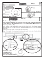
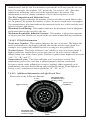
7.4.10 Tire Fundamentals
Federal law requires tire manufacturers to place standardized information on the
VLGHZDOORIDOOWLUHV7KLVLQIRUPDWLRQLGHQWL¿HVDQGGHVFULEHVWKHIXQGDPHQWDO
FKDUDFWHULVWLFVRIWKHWLUHDQGDOVRSURYLGHVDWLUHLGHQWL¿FDWLRQQXPEHUIRUVDIHW\
VWDQGDUGFHUWL¿FDWLRQDQGLQFDVHRIDUHFDOO
7.4.10.1 Information on Passenger Vehicle Tires
Please refer to the diagram on the next page.
51
Radial
Ratio of height to
width (aspect ratio)
Nominal width of
tire in millimeters
Rim diameter
code
Load index &
speed symbol
Passenger
car tire
Tire ply
composition
and materials
used
Max.
permissable
LQÀDWLRQ
pressure
Treadwear, traction
and temperature grades
U.S. DOT tire
LGHQWL¿FDWLRQQXPEHU
Sever snow
conditions
Max. load rating
P:7KH³3´LQGLFDWHVWKHWLUHLVIRUSDVVHQJHUYHKLFOHV
Next number:7KLVWKUHHGLJLWQXPEHUJLYHVWKHZLGWKLQPLOOLPHWHUVRIWKHWLUH
from sidewall edge to sidewall edge. In general, the larger the number, the wider
the tire.
Next number:7KLVWZRGLJLWQXPEHUNQRZQDVWKHDVSHFWUDWLRJLYHVWKHWLUH¶V
ratio of height to width. Numbers of 70 or lower indicate a short sidewall for
improved steering response and better overall handling on dry pavement.
R:7KH³5´VWDQGVIRUUDGLDO5DGLDOSO\FRQVWUXFWLRQRIWLUHVKDVEHHQWKHLQGXVWU\
standard for the past 20 years.
Next number:7KLVWZRGLJLWQXPEHULVWKHZKHHORUULPGLDPHWHULQLQFKHV,I
you change your wheel size, you will have to purchase new tires to match the new
wheel diameter.
Next number:7KLVWZRRUWKUHHGLJLWQXPEHULVWKHWLUH¶VORDGLQGH[,WLV
DPHDVXUHPHQWRIKRZPXFKZHLJKWHDFKWLUHFDQVXSSRUW<RXPD\¿QGWKLV
information in your owner’s manual. If not, contact a local tire dealer. Note: You
PD\QRW¿QGWKLVLQIRUPDWLRQRQDOOWLUHVEHFDXVHLWLVQRWUHTXLUHGE\ODZ
067KH³06´RU³06´LQGLFDWHVWKDWWKHWLUHKDVVRPHPXGDQGVQRZ
FDSDELOLW\0RVWUDGLDOWLUHVKDYHWKHVHPDUNLQJVKHQFHWKH\KDYHVRPHPXGDQG
snow capability.
Speed Rating: The speed rating denotes the speed at which a tire is designed to be
driven for extended periods of time. The ratings range from 99 miles per hour
PSKWRPSK7KHVHUDWLQJVDUHOLVWHGEHORZ1RWH<RXPD\QRW¿QGWKLV
information on all tires because it is not required by law.
* For tires with a maximum speed capability over 149 mph, tire manufacturers
VRPHWLPHVXVHWKHOHWWHUV=5)RUWKRVHZLWKDPD[LPXPVSHHGFDSDELOLW\RYHU
PSKWLUHPDQXIDFWXUHUVDOZD\VXVHWKHOHWWHUV=5
86'277LUH,GHQWL¿FDWLRQ1XPEHU
7KLVEHJLQVZLWKWKHOHWWHUV³'27´DQGLQGLFDWHVWKDWWKHWLUHPHHWVDOO
52
federal standards. The next two numbers or letters are the plant code where it was
manufactured, and the last four numbers represent the week and year the tire was
built. For example, the numbers 3197 means the 31st week of 1997. The other
numbers are marketing codes used at the manufacturer’s discretion. This
information is used to contact consumers if a tire defect requires a recall.
Tire Ply Composition and Materials Used
7KHQXPEHURISOLHVLQGLFDWHVWKHQXPEHURIOD\HUVRIUXEEHUFRDWHGIDEULFLQWKH
tire. In general, the greater the number of plies, the more weight a tire can support
Tire manufacturers also must indicate the materials in the tire, which include steel,
nylon, polyester, and others.
Maximum Load Rating: This number indicates the maximum load in kilograms
and pounds that can be carried by the tire.
0D[LPXP3HUPLVVLEOH,QÀDWLRQ3UHVVXUH This number is the greatest amount
of air pressure that should ever be put in the tire under normal driving conditions.
7.4.10.2 UTQGS Information
Tread-wear Number: This number indicates the tire’s wear rate. The higher the
WUHDGZHDUQXPEHULVWKHORQJHULWVKRXOGWDNHIRUWKHWUHDGWRZHDUGRZQ)RU
example, a tire graded 400 should last twice as long as a tire graded 200.
Traction Letter: This letter indicates a tire’s ability to stop on wet pavement. A
higher graded tire should allow you to stop your car on wet roads in a shorter
distance than a tire with a lower grade. Traction is graded from highest to lowest as
³$$´´$´³%´DQG³&´
Temperature Letter: This letter indicates a tire’s resistance to heat. The
WHPSHUDWXUHJUDGHLVIRUDWLUHWKDWLVLQÀDWHGSURSHUO\DQGQRWRYHUORDGHG
([FHVVLYHVSHHGXQGHULQÀDWLRQRUH[FHVVLYHORDGLQJHLWKHUVHSDUDWHO\RULQ
FRPELQDWLRQFDQFDXVHKHDWEXLOGXSDQGSRVVLEOHWLUHIDLOXUH)URPKLJKHVWWR
ORZHVWDWLUH¶VUHVLVWDQFHWRKHDWLVJUDGHGDV³$´³%´RU³&´
7.4.10.3. Additional Information on Light Truck Tires
Please refer to the following diagram:
Maximum load
Load
range
LQÀDWLRQZKHQ
used as a dual
Severe snow
conditions
Light truck tire
Maximum load
LQÀDWLRQZKHQ
used as a single
/RDGLQÀDWLRQ
limits
53
Tires for light trucks have other markings besides those found on the sidewalls of
passenger tires.
LT:7KH³/7´LQGLFDWHVWKHWLUHLVIRUOLJKWWUXFNVRUWUDLOHUV
ST:$Q³67´LVDQLQGLFDWLRQWKHWLUHLVIRUWUDLOHUXVHRQO\
Max. Load Dual kg (lb) at kPa (psi) Cold: This information indicates the
maximum load and tire pressure when the tire is used as a dual, that is, when four
WLUHVDUHSXWRQHDFKUHDUD[OHDWRWDORIVL[RUPRUHWLUHVRQWKHYHKLFOH
Max. Load Single kg (lb) at kPa (psi) Cold: This information indicates the
maximum load and tire pressure when the tire is used as a single.
Load Range:7KLVLQIRUPDWLRQLGHQWL¿HVWKHWLUH¶VORDGFDUU\LQJFDSDELOLWLHVDQG
LWVLQÀDWLRQOLPLWV
7.4.11 Tire Safety Tips
7.4.11.1 Preventing Tire Damage
6ORZGRZQLI\RXKDYHWRJRRYHUDSRWKROHRURWKHUREMHFWLQWKHURDG
• Do not run over curbs or other foreign objects in the roadway, and try not to
strike the curb when parking.
7.4.11.2 Tire Safety Checklist
&KHFNWLUHSUHVVXUHUHJXODUO\DWOHDVWRQFHDPRQWKLQFOXGLQJWKHVSDUH
• Inspect tires for uneven wear patterns on the tread, cracks, foreign objects, or
other signs of wear or trauma.
• Remove bits of glass and foreign objects wedged in the tread.
• Make sure your tire valves have valve caps.
• Check tire pressure before going on a long trip.
• Do not overload your vehicle.
7.5 Changing a Flat Tire
7.5.1 If possible, get the Trailer on level ground.
7.5.2,ISRVVLEOHNHHSWKH7UDLOHUFRXSOHGWRWKH7RZ9HKLFOHDQGHQJDJHWKH7RZ
9HKLFOH¶VHPHUJHQF\EUDNH,I7RZ9HKLFOHLVQRWFRXSOHGWRWKH7UDLOHUORZHUWKH
Tongue Jack and secure in place with Locking Pin6HHWKHVHFWLRQRQ³7UDLOHU
)HDWXUHV´IRULQVWUXFWLRQVRQXVLQJWKH7RQJXH-DFN
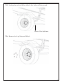
7.5.3&KRFNWKH:KHHO\RXDUHnot changing with bricks or wooden blocks.
54
7.5.4 Place a Tire JackXQGHUWKHSDUWRIWKHD[HOQHDUWKHÀDWWLUH
7.5.5-DFNXSWKHD[OHWROLIWWKHZKHHODIHZLQFKHVRIIWKHJURXQG
3ODFHD7LUH-DFNKHUH
7.5.6 5HPRYHWKH/XJ1XWVDQG:KHHO
55
7.5.7 Place Spare Tire on the axle and tighten Lug Nuts between 95 - 120 ft/lb.
Do not exceed 120 ft./lb.
7.5.8 Tighten Lug Nuts in the following sequence:
1
3
4
5
2
7.5.9 Lower Tire Jack and remove from under Trailer.
7.5.10 Raise the Tongue Jack and secure in place with Locking Pin6HHWKH
VHFWLRQ³7UDLOHU)HDWXUHV´IRULQVWUXFWLRQVRQXVLQJWKH7RQJXH-DFN
WARNING
Never crawl under a trailer on jacks. The trailer could slip off
the jack or the jack could fail resulting in serious injury or death.
WARNING
Lug nuts are prone to loosen after initial installation, which can
lead to death or serious injury.
&KHFNOXJQXWVIRUWLJKWQHVVRQDQHZWUDLOHURUZKHQZKHHOV
KDYHEHHQUHPRXQWHGDIWHUWKH¿UVWDQGPLOHVRIGULY
ing and after any impact.
Lug nuts for the tires must be tightened by the user before each
use. Lifetime Products cannot be held responsible for damages
caused by loosened lug nuts.
56
7.6 Checking the Tire Pressure
Always check the tire pressure before each tow. Use a pressure gauge to ensure
SURSHUWLUHSUHVVXUH7KHWLUHVSURYLGHGZLWK\RXU7UDLOHUVKRXOGEH¿OOHGWR80 psi.
Tire pressure must be checked when the tire is cold. If the trailer has been towed
for at least one mile, allow at least three hours after a tow for the tire to cool before
checking the pressure.
WARNING
To help ensure long tread life and your safety. Always check
tire pressure to ensure optimum life and performance from your
tires. The tires that came with your trailer should have a tire
pressure of 80 psi. Lifetime Products cannot be held responsible
for damages caused by uneven tread wear and blow outs from an
XQGHULQÀDWHGRURYHULQÀDWHGWLUH´
57
SECTION 8: LOADING THE
TRAILER
LOADING THE CARGO
Improper trailer loading causes many accidents and deaths. To safely load a trailer,
you must consider:
2YHUDOOORDGZHLJKW
/RDGZHLJKWGLVWULEXWLRQ
3URSHUWRQJXHZHLJKWDQG
6HFXULQJWKHORDGSURSHUO\
To determine that you have loaded the trailer within its rating, you must consider
the distribution of weight, as well as the total weight of the trailer and its contents.
The trailer axles carry most of the total weight of the trailer and its contents (Gross
9HKLFOH:HLJKWRU³*9:´7KHUHPDLQGHURIWKHWRWDOZHLJKWLVFDUULHGE\WKHWRZ
vehicle hitch. For safe towing, it is essential that the trailer tongue and tow vehicle
hitch carry the proper amount of the loaded trailer weight, otherwise the trailer can
VXGGHQO\VZD\ZLOGO\DWWRZLQJVSHHG5HDGWKH³7RQJXH:HLJKW´VHFWLRQEHORZ
The load distribution must be such that no component part of the trailer is loaded
beyond its rating. This means that you must consider the rating of the tires, wheels
DQGD[OHV)RUWDQGHPDQGWULSOHD[OHWUDLOHUV\RXPXVWPDNHVXUHWKDWWKHIURQWWR
rear load distribution does not result in overloading any axle.
Towing stability also depends on keeping the center of gravity as low as possible.
/RDGKHDY\LWHPVRQWKHÀRRUDQGRYHUWKHD[OHV:KHQORDGLQJDGGLWLRQDOLWHPVEH
VXUHWRPDLQWDLQHYHQVLGHWRVLGHZHLJKWGLVWULEXWLRQDQGSURSHUWRQJXHZHLJKW7KH
total weight of the trailer and its contents must never exceed the total weight rating of
WKHWUDLOHU*URVV9HKLFOH:HLJKW5DWLQJRU³*9:5´
WARNING
An overloaded trailer can result in loss of control of the trailer,
leading to death or serious injury.
Do not load a trailer so that the weight on any tire exceeds its
rating.
'RQRWH[FHHGWKHWUDLOHU*URVV9HKLFOH:HLJKW5DWLQJ*9:5
RUDQD[OH*URVV$[OH:HLJKW5DWLQJ*$:5
Tongue Weight
It is critical to have a portion of the trailer load carried by the tow vehicle. That is,
the trailer tongue must exert a downward force on the hitch. This is necessary for two
reasons. First, the proper amount of tongue weight is necessary for the tow vehicle
to be able to maintain control of the tow vehicle/trailer system. If, for example, the
58
tongue exerts an upward pull on the hitch, instead of pushing down on it (because
WKHWUDLOHULVRYHUORDGHGEHKLQGLWVD[OHVWKHUHDUZKHHORIWKHWRZYHKLFOHFDQ
lose traction or grip and cause loss of control. Also, even if there is some weight on
the tongue, but not enough weight on the tongue, the trailer can suddenly become
unstable at high speeds.
If, on the other hand, there is too much tongue weight, the front wheels of the tow
vehicle can be too lightly loaded and cause loss of steering control and traction, as
well, if the front wheels are driving.
In addition to tow vehicle control, tongue weight is necessary to insure that the trailer
D[OHVGRQRWH[FHHGWKHLU*URVV$[OH:HLJKW5DWLQJ*$:5
7KHWDEOHEHORZKDV³UXOHVRIWKXPE´IRUSURSHUWRQJXHZHLJKW
In the table below, the second column notes the rule of thumb percentage of total
ZHLJKWRIWKHWUDLOHUSOXVLWVFDUJR*URVV9HKLFOH:HLJKWRU³*9:´WKDWVKRXOG
appear on the tongue of the trailer. For example, a trailer with a ball hitch and a
ORDGHGZHLJKWRISRXQGVVKRXOGKDYHRISRXQGVRQWKHWRQJXH
That is, the example trailer would have no more than 100 to 150 pounds on its tongue.
Tongue Weight as a Percentage of Loaded Trailer Weight
Type of Hitch
Percentage
%DOO+LWFKRU%XPSHU+LWFK
±
WARNING
Never go under the trailer unless it has been properly supported
ZLWKMDFNVWDQGVWKDWKDYHEHHQUDWHGIRUWKHORDG:LWKRXWEH
ing properly supported, the trailer may fall suddenly which may
UHVXOWLQVHULRXVLQMXU\RUGHDWK´
WARNING
,PSURSHUWRQJXHZHLJKWORDGGLVWULEXWLRQFDQUHVXOWLQORVVRI
control of the trailer, leading to death or serious injury.
Make certain that tongue weight is within the allowable range.
Be sure to:
'LVWULEXWHWKHORDGIURQWWRUHDUWRSURYLGHSURSHUWRQJXH
ZHLJKWVHHFKDUW
• Distribute the load evenly, right and left, to avoid tire over
ORDGDQG
• Keep the center of gravity low.
59
8.1. Checking the Tongue Weight
To check the tongue weight, the tow vehicle and trailer must be on level ground, as
they will be when the trailer is being towed.
If you know the weight on your tow vehicle’s axles when you are not towing a trailer,
trailer tongue weight can be determined with the use of a truck axle scale.
The recommended method of checking tongue weight is to use an accessory called a
³WRQJXHZHLJKWVFDOH´,IDWRQJXHZHLJKWVFDOHLVQRWDYDLODEOH\RXFDQFKHFNWKH
tongue weight using a bathroom scale.
Using a bathroom scale to check tongue weight: The loaded trailer must be on a
smooth and level surface, and you must block the trailer wheels, front and rear.
8.1.1 Checking Tongue Weight — Using a lever and bathroom scale
WARNING
An unrestrained trailer can fall off its support, resulting in seri
ous injury or death.
Before checking tongue weight, block trailer wheels, front and rear.
• Raise the tongue of the trailer with the tongue jack.
• Place a bathroom scale on the ground, directly below the coupler.
3ODFHDVWURQJEORFNVXSSRUWVXFKDVDFHPHQWEORFNRQWKHVFDOH±QRWHWKH
scale reading for the weight of the block support.
• Lower the tongue until the coupler rests on the block support and the jack is ½
inch above the ground.
• The scale reading, minus the weight of the block support is the tongue weight.
8.2 Securing the Cargo
6LQFHWKHWUDLOHU³ULGH´FDQEHEXPS\DQGURXJK\RXPXVWVHFXUH\RXUFDUJRVRWKDW
it does not shift while the trailer is being towed.
WARNING
6KLIWLQJFDUJRFDQUHVXOWLQORVVRIFRQWURORIWKHWUDLOHUDQGFDQ
lead to death or serious injury.
Tie down all loads with proper sized fasteners, ropes, straps, etc.
8.2.1 Loading Cargo
Couple the trailer to the tow vehicle before loading. This is essential because the
tongue can rise during loading, before the cargo is properly distributed. To
measure the tongue weight, you will have to uncouple the trailer after it is loaded.
Do not transport people in the trailer. Do not transport containers of hazardous
VXEVWDQFHVFDQVRUFRQWDLQHUVRIÀDPPDEOHVXEVWDQFHVVXFKDVJDVROLQH
60
NHURVHQHSDLQWHWF+RZHYHUIXHOLQWKHWDQNRIDQRIIURDGYHKLFOHRUDFDURU
motorcycle, etc. may be carried on your open trailer.
WARNING
'RQRWWUDQVSRUWÀDPPDEOHH[SORVLYHSRLVRQRXVRURWKHU
dangerous materials in your trailer. Failure to heed this warning
could result in property damage, serious injury and death.
Exceptions:
• Fuel in the tanks of vehicles that are being towed
• Fuel stored in proper containers used in trailer living quar
ters for cooking
)XHOVWRUHGLQWKHWDQNRIDQRQERDUGJHQHUDWRU
8.2.1.1 Preparing the Trailer for Loading
Before loading cargo onto the trailer:
LQVSHFWWKHGHFNRIWKHWUDLOHUIRUFRUURVLRQRUGDPDJHDQG
LQVSHFWWKHKROGGRZQRSHQLQJVDQGRU³'´ULQJV+ROGGRZQRSHQLQJVPXVW
EHVWXUG\ZLWKQRYLVLEOHFUDFNVRUNLQNV'ULQJVPXVWEHWLJKWWRWKHGHFNDQG
must not be bent.
,IWKHGHFNRUDQ\UHTXLUHGKROGGRZQLVGDPDJHGGRQRWORDGWKHFDUJR%ULQJ
the trailer to your dealer or a competent repair service before using it to carry
cargo.
WARNING
'DPDJHGRUORRVH³'´ULQJVFDQEUHDNDOORZLQJFDUJRWREHFRPH
loose inside the trailer. Loose cargo can shift the center of gravity,
and result in loss of control of the trailer.
,QVSHFW ³'´ULQJV DQG WHVW WKHP IRU ORRVHQHVV EHIRUH ORDGLQJ
cargo.
'RQRWXVHDGDPDJHGRUORRVH³'´ULQJWRVHFXUHFDUJR
Failure to head this warning could result in property damage,
serious injury and death.
8.2.1.2 Loading the Trailer
Before loading the trailer, couple the trailer to the tow vehicle and ensure the
deck is level. Do not load or unload the trailer when the deck is not level.
(QVXUHWKHWRSRIWKHUDPSRUUDPSVLVVHFXUHWRWKHWUDLOHUDQGWKHERWWRP
LVUHVWLQJRQ¿UPJURXQG3RFNHWVPD\EHSURYLGHGWRKROGWKHUDPSWRWKH
frame of the trailer.
2. Load the cargo onto the trailer.
6HFXUHWKHFDUJRWRWKHWUDLOHUXVLQJDSSURSULDWHVWUDSVFKDLQVDQGWHQVLRQLQJ
devices.
6LQFHWKHWUDLOHU³ULGH´FDQEHEXPS\DQGURXJK\RXPXVWVHFXUH\RXUFDUJRVR
61
that it does not shift while the trailer is being towed.
WARNING
Load can suddenly move or topple, which can result in death or
serious injury.
Do not load or unload your open trailer unless it is prevented
IURPWLSSLQJDQGLVRQ¿UPDQGOHYHOJURXQG
5HWXUQWKHUDPSVWRWKHLUVWRZHGSRVLWLRQVDQGVHFXUHWKHPVRWKDWWKH\ZLOO
not move during transit.
WARNING
6KLIWLQJFDUJRFDQUHVXOWLQORVVRIFRQWURORIWKHWUDLOHUDQGFDQ
lead to death or serious injury.
Tie down all loads with proper sized fasteners, ropes, straps, etc.
WARNING
'R127XVHWKH*DWHIRUWLHGRZQORFDWLRQV$OODUWLFOHVEHLQJ
towed must be tied to the side walls of the Trailer. Gate can
dislodge causing property damage and possible injury or death to
other motorists and pedestrians.
WARNING
Do not transport people in the trailer. Failure to heed this warn
ing could result in serious injury such as broken bones, brain
damage, paralysis or death.
62
SECTION 9: CHECK TRAILER
BEFORE & DURING TOWING
PRE-TOW CHECKLIST
9.1 Before Towing, Double Check All These Items:
• Tires, wheels and lug nuts (see the section “Breaking in New Trailer“ and the
VHFWLRQRQ³7LUH6DIHW\,QIRUPDWLRQ³
&RXSOHUVHFXUHGDQGORFNHGVHHWKHVHFWLRQ³&RXSOLQJWRWKH7RZ9HKLFOH´
6DIHW\FKDLQVSURSHUO\ULJJHGWRWRZYHKLFOHQRWWRKLWFKRUEDOOVHHWKHVHFWLRQ
³&RXSOLQJWRWKH7RZ9HKLFOH´RIWKLVPDQXDO
7HVWRIOLJKWV7DLO6WRS7XUQDQG%DFNXS
• Cargo properly loaded, balanced and tied down (see the section “Loading the
7UDLOHU´RIWKLVPDQXDO
• Tongue weight
• Doors and gates latched and secured
)ODUHVDQGUHÀHFWRUV
WARNING
An improperly coupled trailer can result in death or serious
injury.
Do not move the trailer until:
7KHFRXSOHULVVHFXUHGDQGORFNHGWRKLWFK
7KHVDIHW\FKDLQVDUHVHFXUHGWRWKHWRZYHKLFOHDQG
7KHWUDLOHUMDFNVDUHIXOO\UHWUDFWHG
Do not tow the trailer on the road until:
7LUHVDQGZKHHOVDUHFKHFNHG
7KHORDGLVVHFXUHGWRWKHWUDLOHUDQG
• The trailer lights are connected and checked.
MAKE REGULAR STOPS
9.2 After Each 50 Miles, or One Hour of Towing, Stop and Check the Following
Items:
• Coupler secured
6DIHW\FKDLQVDUHIDVWHQHGDQGQRWGUDJJLQJ
• Cargo secured
• Cargo door latched and secured
63
WARNING
6LQFHURDGVFDQEHEXPS\DQGURXJKOXJQXWVFDQORRVHQRYHU
time and even separate from the wheel and possibly causing the
separation of the wheel from the trailer. The lug nuts must be
tightened by the user before each use.
The tires must be maintained at the proper tire pressure before
each use. Lifetime cannot be held responsible for damages
caused by loosened lug nuts, or uneven tread wear and blow outs
IURPDQXQGHULQÀDWHGRURYHULQÀDWHGWLUH
Failure to heed these warnings could result in personal injury,
property damage and death.
WARNING
'R127XVHWKH*DWHIRUWLHGRZQORFDWLRQV$OODUWLFOHVEHLQJ
towed must be tied to the side walls of the Trailer. Gate can
dislodge causing property damage and possible injury or death to
other motorists and pedestrians.
Follow local and state laws, but do not exceed 65 mph.
WARNING
Do not transport people in the trailer. Failure to heed this warn
ing could result in serious injury such as broken bones, brain
damage, paralysis or death.
64
SECTION 10: BREAKING IN A
NEW TRAILER
LUG NUTS & TIRE PRESSURE
10.1 Retightening Lug Nuts at First 10, 25 & 50 Miles
:KHHOOXJVFDQVKLIWDQGVHWWOHTXLFNO\DIWHUEHLQJ¿UVWDVVHPEOHGDQGPXVWEH
FKHFNHGDIWHUWKH¿UVWDQGPLOHVRIGULYLQJDQGDIWHUDQ\LPSDFW)DLOXUH
to perform this check may result in a wheel coming loose from the trailer, causing a
crash leading to death or serious injury.
WARNING
Lug nuts are prone to loosen after initial installation, which can
lead to death or serious injury.
&KHFNOXJQXWVIRUWLJKWQHVVRQDQHZWUDLOHURUZKHQZKHHOV
KDYHEHHQUHPRXQWHGDIWHUWKH¿UVWDQGPLOHVRIGULY
ing and after any impact.
WARNING
The lug nuts for the tires must be tightened by the user before
each use. The tires must be maintained at the proper tire pres
sure before each use. Lifetime cannot be held responsible for
damages caused by loosened lug nuts, or uneven tread wear and
EORZRXWVIURPDQXQGHULQÀDWHGRURYHULQÀDWHGWLUH
Failure to heed this warning could result in property damage,
serious injury and death.
WARNING
If tow vehicle brakes do not work properly, death or serious
injury can occur.
Road test your tow vehicle’s brakes in a safe area at no more
than 30 mph before each tow.
10.2 Tire Pressure
Check the pressure in each tire to ensure tire is set to the tire manufacturers
UHFRPPHQGHGSUHVVXUH7KHWLUHVWKDWFDPHZLWK\RXUWUDLOHUVKRXOGEH¿OOHGWR
80 psi. Use a tire gauge to get an accurate reading. You should check the pressure
before each tow.
65
SECTION 11: MAINTENANCE
INSPECTION, SERVICE & MAINTENANCE
11.1 Inspection, Service & Maintenance Summary Charts
You must inspect, maintain and service your trailer regularly to insure safe and
reliable operation. If you cannot or are unsure how to perform the items listed here,
have your dealer do them.
Note: In addition to this manual, also check the relevant component
manufacturer’s manual.
Inspection and Service before Each Use
Item
Inspection/Service
Coupler and Hitch Ball
Check for cracks, pits, and
ÀDWV5HSODFHZEDOOFRXSOHU
KDYLQJWUDLOHU*9:5DWLQJ
Grease
&KHFNORFNLQJGHYLFHUHSODFH
Manual Section Reference
6HFWLRQ
6DIHW\&KDLQV+RRNV
Check for wear and damage
6HFWLRQV
Tires
• Air Pressure
Check tire pressure when cold
,QÀDWHWLUHVWRSVL
6HFWLRQV
:KHHOV
/XJ1XWV%ROWV+XE
Check for tightness
7LJKWHQWRIWOE'R
not exceed 120 ft./lb. For new
and remounted wheels, check
WRUTXHDIWHU¿UVW
miles of driving and after any
impact
6HFWLRQ
6HFWLRQV
Inspection and Service each 3 Months or 3,000 Miles
Item
Inspection/Service
Manual Section Reference
6WUXFWXUH
• Hinges, Doors
Inspect. Repair or replace
damaged, worn or broken parts
6HFWLRQ
11.2.2.1
:KHHOV
• Rims
Inspect for dents, damage or out
of round
11.2.7
Tires
Inspect for cuts wear and
bulging
Basic tire maintenance
6HFWLRQV
7.4.4, 7.4.5, 7.4.6, 7.4.7, 7.4.8,
Inspection and Service each 6 Months or 6,000 Miles
Item
Inspection/Service
Manual Section Reference
Tires
Rotate @ 5,000 miles
6HFWLRQ
66
:KHHOV
816($/('%HDULQJV+XEV
&KHFNDQGFRQ¿UPIUHHUXQQLQJ 6HFWLRQ
Replace if not.
6HFWLRQ
Disassemble / inspect / as
6HH$[OH0IU¶V0DQXDO
semble and repack. Replace
promptly if immersed in water
Inspection and Service each 6 Months or 6,000 Miles
6XVSHQVLRQ
Inspect for bending loose fas
teners, wear
6HH6XVSHQVLRQ0DQXIDFWXUHU¶V
Manual
Inspection and Service Each Year or 12,000 Miles
Item
Inspection/Service
6WUXFWXUH
• Frame members
:HOGV
6OLGHRXW
Inspect all frame members, bolts
ULYHWV5HSDLURUUHSODFHGDP
aged, worn or broken parts.
Inspect all welds. Repair as
needed
&OHDQGLUWEXLOGXS/XEULFDWH
slides, shafts and gears
6WUXFWXUH
• Axle Attachment Bolts
Check BY DEALER
Manual Section Reference
6HFWLRQ
6HFWLRQ
6HFWLRQ
6HFWLRQ
6HH$[OH0DQXIDFWXUHU¶V0DQXDO
11.2 Inspection and Service Instructions
11.2.1 Axle Bolts, Frame, Suspension, & Structure
WARNING
:RUQ RU EURNHQ VXVSHQVLRQ SDUWV FDQ FDXVH ORVV RI FRQWURO DQG
property damage, serious injury and death may result. Have trail
er professionally inspected annually and after any impact.
To perform many of the inspection and maintenance activities, you must jack up the
trailer.
:KHQMDFNLQJDQGXVLQJMDFNVWDQGVSODFHWKHPVRDVWRFOHDUZLULQJDQGVXVSHQVLRQ
SDUWVVSULQJVWRUVLRQEDUVHWF3ODFHMDFNVDQGMDFNVWDQGVLQVLGHRIWKHSHULPHWHU
strip on the supporting structure to which the axles are attached.
WARNING
1HYHUFUDZOXQGHU\RXUWUDLOHUXQOHVVLWLVRQ¿UPDQGOHYHOJURXQG
and resting on properly placed and secured jack stands.
Failure to heed this warning could result in property damage, seri
ous injury and death.
67
3ODFH7LUH-DFNKHUH
Figure 10 - 1: Jacking Points
11.2.2 Trailer Structure
%HFDXVHWKHWUDLOHUÀRRUUHFHLYHVWKHPRVWDEXVHLWZLOOPRVWOLNHO\FRUURGHEHIRUH
DQ\RWKHUSDUWRIWKHVWUXFWXUH8VLQJDSRZHUZDVKHUZDVKWKHÀRRUDQGZDOOVRI
the trailer after each use.
11.2.2.1 Fasteners and Frame Members
Inspect all of the fasteners and structural frame members for bending and other
damage, cracks, or failure. Repair or replace any damaged fastener and repair the
frame member. If you have any questions about the condition or method of repair
of fasteners or frame members, get the recommendation of, or have the repair done
by, your dealer.
The various fastener types used on your trailer are:
• Bolts, which are used mainly for attaching door and gate hinges to the trailer
ERG\
• Buck Rivets, which are used to attach the sides and roof panels of the body to
HDFKRWKHUDQGWRWKHIUDPHRIWKHWUDLOHUDQG
+XFN%ROWVPD\EHDWYDULRXVORFDWLRQVRQWKHVXEIUDPH+XFNEROWVDUHQRW
user serviceable. If you detect a loose huck bolt fastener, do not tow the trailer.
Call your dealer for instructions.
WARNING
Broken or damaged fasteners or welds can cause serious injury,
damage to trailer and contents and death. Inspect for, and repair
all damaged parts at least once a year.
11.2.2.2 Welds
All welds can crack or fail when subjected to heavy loads or movement of cargo
that was not properly tied to prevent movement. Any time you know or suspect
the trailer has been subjected to heavy loads or movement of cargo, immediately
68
inspect the welds and fasteners for damage. To prevent severe damage to your
trailer, inspect all of the welds for cracks or failure at least once a year.
WARNING
Improper weld repair will lead to early failure of the trailer struc
ture and can cause serious injury or death. Do not repair cracked
or broken welds unless you have the skills and equipment to
make a proper repair. If not, have the welds repaired by a certi
¿HGZHOGHU
11.2.3 Trailer Connection to Tow Vehicle
11.2.3.1 Coupler and Ball
The coupler on the trailer connects to the ball attached to the hitch on the tow
vehicle. The coupler, ball and hitch transfer the towing forces between the
tow vehicle and the trailer. Before each tow, coat the ball with a thin layer of
DXWRPRWLYHEHDULQJJUHDVHWRUHGXFHZHDUDQGHQVXUHSURSHURSHUDWLRQDQGFKHFN
the locking device that secures the coupler to the ball for proper operation.
,I\RXVHHRUIHHOHYLGHQFHRIZHDUVXFKDVÀDWVSRWVGHIRUPDWLRQVSLWWLQJRU
corrosion, on the ball or coupler, immediately have your dealer inspect them to
determine the proper action to prevent possible failure of the ball and coupler
system. All bent or broken coupler parts must be replaced before towing the trailer.
The coupler handle lever must be able to rotate freely and automatically snap into
the latched position. Oil the pivot points, sliding surfaces, and spring ends with
6$(:PRWRURLO.HHSWKHEDOOSRFNHWDQGODWFKPHFKDQLVPFOHDQ'LUWRU
contamination can prevent proper operation of the latching mechanism.
:KHQUHSODFLQJDEDOOWKHORDGUDWLQJPXVWPDWFKRUH[FHHGWKH*9:5RIWKH
trailer.
11.2.4 Landing Leg or Jack
,IDJUHDVH¿WWLQJLVSUHVHQW\RXPXVWXVHDJUHDVHJXQWROXEULFDWHWKHMDFN
PHFKDQLVP*UHDVHWKHJHDUVLQWKHWRSRIKDQGFUDQNHGMDFNVRQFHD\HDUE\
removing the top of the jack and pumping or hand packing grease into the gears.
11.2.5 Lights and Signals
Before each tow, check the trailer taillights, stoplights, turn signals and any
clearance lights for proper operation.
WARNING
Improper operating taillights, stoplights and turn signals can
cause collisions. Check all lights before each tow. Failure to
heed this warning could result in property damage, serious injury
and death.
69
11.2.6 Tires
Before each tow, be sure the tire pressure is at the value indicated on the sidewall.
Tire pressure must be checked while the tire is cold. Do not check the tire pressure
immediately after towing the trailer. Allow at least three hours for a tire to cool, if
the trailer has been towed for as much as one mile. Replace the tire before towing
the trailer if the tire treads have less than 1/16 inch depth or the telltale bands are
visible.
A bubble, cut or bulge in a side wall can result in a tire blowout. Inspect both side
ZDOOVRIHDFKWLUHIRUDQ\EXEEOHFXWRUEXOJHDQGUHSODFHDGDPDJHGWLUHEHIRUH
towing the trailer.
Tires do not wear evenly. Depending on the load balance, some will wear faster
than others. To help increase the life of your tires, rotate tires every 5000 miles.
WARNING
:RUQGDPDJHGRUXQGHULQÀDWHGWLUHVFDQFDXVHORVVRIFRQWURO
resulting in damage, serious injury and possibly death. Inspect
tires before each tow.
11.2.7 Wheel Rims
If the trailer has been struck, or impacted, on or near the wheels, or if the trailer has
VWUXFNDFXUELQVSHFWWKHULPVIRUGDPDJHHJEHLQJRXWRIURXQGDQGUHSODFH
any damaged wheel. Inspect the wheels for damage every year, even if no obvious
impact has occurred. Also check the tires to ensure they’re at the recommended
pressure.
11.2.8 Wheels, Bearings and Lug Nuts
7RFKHFN\RXUEHDULQJVMDFNWUDLOHUDQGFKHFNZKHHOVIRUVLGHWRVLGHORRVHQHVV
If the wheels are loose, or spin with a wobble, the bearings must be serviced or
replaced.
0RVWWUDLOHUD[OHVDUHEXLOWZLWKVHDOHGEHDULQJVWKDWDUHQRWVHUYLFHDEOH6HDOHG
bearings must be replaced as complete units.
11.2.8.1 Unsealed Bearings (Hubs)
You must inspect and lubricate the bearings once a year or every 12,000 miles to
insure safe operation of your trailer.
If a trailer wheel bearing is immersed in water, it must be replaced.
If your trailer has not been used for an extended amount of time, have the bearings
inspected and packed more frequently, at least every six months and prior to use.
)ROORZWKHVWHSVEHORZWRGLVDVVHPEOHDQGVHUYLFHWKH816($/('ZKHHO
70
bearings.
• After removing the grease cap, cotter pin, spindle nut and spindle washer,
remove the hub and drum to inspect the bearings for wear and damage.
5HSODFHEHDULQJVWKDWKDYHÀDWVSRWVRQUROOHUVEURNHQUROOHUFDJHVUXVWRU
pitting. Always replace bearings and cups in sets. The inner and outer bearings
are to be replaced at the same time.
• Replace seals that have nicks, tears or wear.
/XEULFDWHWKHEHDULQJVZLWKDKLJKTXDOLW\(3DXWRPRWLYHZKHHOEHDULQJ
grease.
Every time the wheel hub is removed and the bearings are reassembled, follow the
steps below to check the wheel bearings for free running and adjust.
• Turn the hub slowly, by hand, while tightening the spindle nut, until you can no
longer turn the hub by hand.
/RRVHQWKHVSLQGOHQXWMXVWXQWLO\RXDUHDEOHWRWXUQLWWKHVSLQGOHQXWE\
hand. Do not turn the hub while the spindle nut is loose.
• Put a new cotter pin through the spindle nut and axle.
• Check the adjustments. Both the hub and the spindle nut should be able to
PRYHIUHHO\WKHVSLQGOHQXWPRWLRQZLOOEHOLPLWHGE\WKHFRWWHUSLQ
11.2.9 Lug Nuts (Bolts)
/XJQXWVDUHSURQHWRORRVHQULJKWDIWHUDZKHHOLVPRXQWHGWRDKXE:KHQGULYLQJ
RQDUHPRXQWHGZKHHOFKHFNWRVHHLIWKHOXJQXWVDUHWLJKWDIWHUWKH¿UVWDQG
50 miles of driving and before each tow thereafter.
WARNING
Lug nuts are prone to loosen after initial installation, which can
lead to death or serious injury.
&KHFNOXJQXWVIRUWLJKWQHVVRQDQHZWUDLOHURUZKHQZKHHOV
KDYHEHHQUHPRXQWHGDIWHUWKH¿UVWDQGPLOHVRI
driving.
WARNING
Metal creep between the wheel rim and lug nuts will cause rim to
loosen and could result in a wheel coming off, leading to death or
serious injury. Tighten lug nuts before each tow.
71
1
3
5
4
2
Figure 11 - 2: Lug nut sequence of tightening
Tighten the lug nuts to the proper torque for the axle size on your trailer, to prevent
wheels from coming loose. Use a torque wrench to tighten the fasteners. If you do
not have a torque wrench, tighten the fasteners with a lug wrench as much as you
can, then have a service garage or dealer tighten the lug nuts to the proper torque.
2YHUWLJKWHQLQJZLOOUHVXOWLQEUHDNLQJWKHVWXGVRUSHUPDQHQWO\GHIRUPLQJWKH
mounting stud holes in the wheels. Do not exceed 120 ft./lb.
72
Notes:
73
Notes:
74
SECTION 12: WARRANTY
INFORMATION
UTILITY TRAILER
2-YEAR LIMITED FACTORY WARRANTY
Lifetime Products, Inc. reserves the right to make substitutions to warranty claims if
parts are unavailable or obsolete.
1. Lifetime utility trailers are warranted to the original purchaser to be free from de
fects in material and workmanship for a period of two years from the date of origi
QDO UHWDLO SXUFKDVH 7KH ZRUG ³GHIHFWV´ LV GH¿QHG DV LPSHUIHFWLRQV WKDW LPSDLU WKH
use of the product. Defects resulting from misuse, abuse or negligence will void
this warranty. This warranty does not cover defects due to improper installation,
alteration, or accident. This warranty does not cover damage caused by vandalism,
UXVWLQJ ³DFWV RI QDWXUH´ RU DQ\ RWKHU HYHQW EH\RQG WKH FRQWURO RI WKH PDQXIDFWXUHU
2. The tires, wheels, hubs, springs and axle included with the trailer are not covered
by this 2 year limited factory warranty, but are covered by separate 1 year warranty.
3. This warranty is nontransferable and is expressly limited to the repair or replace
PHQW RI SDUWV ZKLFK PD\ EH GHWHUPLQHG XSRQ LQVSHFWLRQ E\ WKH PDQXIDFWXUHU WR
EH GHIHFWLYH LQ PDWHULDO RU ZRUNPDQVKLS 6KLSSLQJ FKDUJHV WR DQG IURP WKH IDFWR
ry as well as labor costs are not covered and are the responsibility of the purchaser.
7KLVZDUUDQW\GRHVQRWFRYHUVFUDWFKLQJRUVFXI¿QJRIWKHSURGXFWWKDWPD\UHVXOW
from normal usage. In addition, defects resulting from intentional damage, negligence,
unreasonable use, improper loading or overloading, installation of improper equip
ment, improper towing, failure to ensure lug nuts are tight will void this warranty.
5. Liability for incidental or consequential damages is excluded to the extent per
PLWWHG E\ ODZ :KLOH HYHU\ DWWHPSW LV PDGH WR HPERG\ WKH KLJKHVW GHJUHH RI VDIH
ty in the trailer, freedom from injury cannot be guaranteed. The user assumes all
risk of injury resulting from the use of this product. All merchandise is sold on this
condition, and no representative of the company may waive or change this policy.
6. This warranty is expressly in lieu of all other warranties, expressed or implied,
LQFOXGLQJZDUUDQWLHVRIPHUFKDQWDELOLW\RU¿WQHVVIRUXVH1HLWKHU/LIHWLPH3URGXFWV
Inc. nor any representative assumes any other liability in connection with this product.
75
ALL TRAILER WARRANTY CLAIMS MUST BE ACCOMPANIED BY A
SALES RECEIPT.
REPORT PRODUCT DEFECTS IN WRITING TO:
/LIHWLPH3URGXFWV,QF32%R[%OGJ'&OHDU¿HOG87RU
FDOO0)DPWRSP067
3OHDVHLQFOXGH\RXUGDWHGVDOHVUHFHLSWDQGSKRWRJUDSKVRIGDPDJHGSDUWV
FOR TIRE WARRANTY CLAIMS REFER TO TIRE MANUFACTURER’S
BROCHURE
76