1
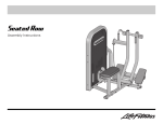
Seated Leg Curl
Assembly Instructions
Seated Leg Curl
Assembly Instructions
Item
Qty
1
2
3
4
5
6
7
8
9
10
11
12
13
14
15
16
17
18
19
20
21
22
23
24
25
26
27
1
1
1
4
67
22
1
6
1
3
3
1
1
2
1
1
1
6
1
1
4
10
3
1
2
1
7
Description
Part Number
Front Brace
Rear Brace
Tower
M10 x 130mm Bolt
3/8” Flat Washer
M10 Nylock Nut
Seat Frame
M10 x 90mm Bolt
Top Brace
M10 x 35mm Bolt
M10 x 70mm Bolt
Main Pivot Bracket
Tower Support Plate
M10 x 75mm Bolt
Output Cam
Output Plate
Output Ring
M10 x 45mm Bolt
Rear Shroud
Front Shroud
M10 x 20mm Bolt
M10 x 25mm Bolt
Plate
Cam Guard
80176XX
80175XX
79854XX
3251720
3102514
3242002
80211XX
3251715
80214XX
3251704
3251711
80078XX
80089XX
3251712
7998601
7998495
7998895
3251706
8024804
8024704
3251701
3251702
7322301
8013201
3239101
80218XX
3251703
M5 x 10mm Phillips Screw
Knee Support
M10 x 30mm Bolt
Tools Required:
O
17mm Wrench
O
Rubber Mallet
O
Metric Allen Wrench Set
O
Ratchet Extension
O
Ratchet with 17mm Socket
O
Phillips Screwdriver
Item
Qty
28
29
30
31
32
33
34
35
36
37
38
39
40
41
42
43
44
45
46
47
48
49
50
51
52
53
1
2
1
1
1
1
2
1
1
1
2
1
1
1
1
1
1
1
2
1
1
1
1
2
4
1
Description
Part Number
Long Spacer
Bearing
Work Arm
Bearing Housing Cap
Counter Weight
Medium Spacer
Bearing
Short Spacer
Knee Handles
M10 x 25mm Hex Bolt
Bearing Housing Cap
Knee Pad
Seat Pad Lead Edge
Seat Pad
Shaft Collar
Roller Pad
Cable
Cable Retaining Plate
Hex Jam Nut
Output Cam Cover Plate
Fender Washer
1 1/2” Endcap
Pad Support Plate
Leveling Shim
1” Hole Plug
Multi-language Label
7511503
3243201
80215XX
7922701
8008801
7330006
3235601
7330001
80217XX
3251202
7308701
74707XX
77678XX
74015XX
7357901
73928XX
8021601
8001801
3247502
7998995
3236701
3119306
8031201
7893101
3237403
8047101
Seated Leg Curl
Assembly Instructions
1. LOOSELY assemble the FRONT BRACE (1) and REAR BRACE (2) to the
TOWER (3) using four M10 X 130mm BOLTS (4), eight 3/8" SAE WASHERS (5) and four M10 NYLOCK NUTS (6) as shown.
2. LOOSELY assemble the SEAT FRAME (7) to the FRONT BRACE (1) and
REAR BRACE (2) using four M10 X 90mm BOLTS (8), eight 3/8" SAE
WASHERS (5) and four M10 NYLOCK NUTS (6) as shown.
3. LOOSELY assemble the TOP BRACE (9) to the SEAT FRAME (7) and
TOWER (3) using two M10 X 35mm BOLTS (10), four 3/8" SAE WASHERS (5) and two M10 NYLOCK NUTS (6) at the SEAT FRAME and two
M10 X 70mm BOLTS (11), four 3/8" SAE WASHERS (5) and two M10
NYLOCK NUTS (6) at the TOWER as shown.
4. Tighten all BOLTS and NUTS securely.
5
Assemble the MAIN PIVOT BRACKET (12) to the TOWER (3) using one
TOWER SUPPORT PLATE (13) (as shown), two M10 X 75mm BOLTS (14),
four 3/8" SAE WASHERS (5) and two M10 NYLOCK NUTS (6) at the top
of the MAIN PIVOT BRACKET. Use one M10 X 70mm BOLT (11), two 3/8"
SAE WASHERS (5) and one M10 NYLOCK NUTS (6) at the bottom of the
MAIN PIVOT BRACKET. Tighten the BOLTS and NUTS securely.
6. Assemble the OUTPUT CAM (15), OUTPUT PLATE (16), and OUTPUT
RING (17) using three M10 X 45mm BOLTS (18) and three 3/8" SAE
WASHERS (5) as shown. Tighten the BOLTS securely.
7. Assemble the REAR SHROUD (19) and FRONT SHROUD (20) to the
TOWER (3) using four M10 X 20mm BOLTS (21), four 3/8" SAE WASHERS (5) as shown. Be sure all tabs along the sides and top of the
SHROUDS are fully engaged in the slots located inside the TOWER.
Tighten the BOLTS securely. Do not over-tighten the BOLTS.
8. Secure the OUTPUT CAM ASSEMBLY (A) to
the TOWER AXLE (B) using one M10 X 25mm
BOLTS (22), one 3/8" SAE WASHERS (5) and
one PLATE (23) as shown. Tighten the BOLT
securely.
IMPORTANT: Be sure the OUTPUT CAM
ASSEMBLY is oriented as shown before securing it to the TOWER HUB.
9. Attach the CAM GUARD (24) to the FRONT
SHROUD (20) using two M5 X 10mm PHILLIPS
SCREWS (25). Tighten the SCREWS securely.
Do not overtighten the SCREWS.
Seated Leg Curl
Assembly Instructions
10. Attach the KNEE SUPPORT (26) to the MAIN PIVOT BRACKET (12) and
SEAT FRAME (7) using seven M10 X 30mm BOLTS (27), fourteen 3/8"
SAE WASHERS (5) and seven M10 NYLOCK NUTS (6) as shown. Tighten
the BOLT and NUTS securely.
Insert the KNEE SUPPORT ENDCAP (49).
11. Insert the LONG SPACER (28) and two BEARINGS (29) into the MAIN
PIVOT BRACKET (12) as shown. Carefully insert the WORKARM (30) into
the MAIN PIVOT BRACKET and secure it with one M10 X 25mm BOLT
(22), one 3/8" SAE WASHER (5) and one PLATE (23). Tighten the BOLT
securely.
Insert the BEARING HOUSING CAP (31) as shown.
12. Attach the COUNTER WEIGHT (32) to the WORKARM (30) using two M10
X 90mm BOLTS (8) and two 3/8" SAE WASHERS (5). Tighten the BOLTS
securely.
13. Insert the MEDIUM SPACER (33), two BEARINGS (34) and one SHORT
SPACER (35) into the KNEE SUPPORT (26) as shown. Carefully insert the
KNEE HANDLES (36) into the KNEE SUPPORT and secure it with one
M10 X 25mm HEX BOLT (37) and one FENDER WASHER (48). Tighten
the BOLT securely.
Insert the BEARING HOUSING CAP (38) as shown.
14. Attach the KNEE PAD (39) to the KNEE HANDLES (36) using two M10 X
25mm BOLTS (22) and two 3/8" SAE WASHERS (5). Tighten the BOLTS
securely.
15. Attach the PAD SUPPORT PLATE (50), SEAT PAD LEAD EDGE (40) and
SEAT PAD (41) to the SEAT FRAME (7) using six M10 X 25mm BOLTS
(22) and six 3/8" SAE WASHERS (5). Tighten the BOLTS securely.
16. Slide the SHAFT COLLAR (42) over the long shaft of the WORKARM (29).
Slide the ROLLER PAD (43) over the long shaft of the WORKARM in similar fashion. Install one M10 X 35mm BOLT (10), one 3/8" SAE WASHERS
(5) and one PLATE (23) to the end of the long shaft of the WORKARM as
shown. Tighten the BOLT securely.
Slide the SHAFT COLLAR against the ROLLER PAD and tighten the set
screw securely.
Insert the BEARING HOUSING CAP (38) onto the end of the ROLLER PAD
as shown.
Seated Leg Curl
Assembly Instructions
NOTE: Some components have been removed from the illustration for
clarity.
17. Insert one end of the CABLE (44) into the cam of the WORKARM (29).
Thread the cable approximately 1/2 inch into the cam.
Route the CABLE beneath the CAM GUARD (24) and around the OUTPUT
CAM ASSEMBLY (A). Insert the remaining end of the CABLE through the
inner hole of the OUTPUT CAM ASSEMBLY.
Insert the CABLE RETAINING PLATE (45) over the end of the CABLE.
Install two HEX JAM NUTS (46) to the end of the CABLE.
Tighten the HEX JAM NUTS until the WORKARM begins to move and all
PUSH PINS (B) still move in and out freely. Be sure the HEX JAM NUTS
are tight against each other.
18. Attach the OUTPUT CAM COVER PLATE (47) to the OUTPUT CAM
ASSEMBLY (A) using three M10 X 45mm BOLTS (18) and three 3/8" SAE
WASHERS (5).
19. Place the unit in the intended place for use and check stability. If the unit
is not stable, the FEET (C) can be adjusted by inserting or removing supplied SHIMS (51).
To add or remove SHIMS, loosen the LEVELING FOOT BOLT (D) and
NUT (6) until the desired SHIM(S) can be inserted or removed. Lightly
tighten the BOLT and NUT. Do not over-tighten the BOLTS.
20. Install HOLE PLUGS in all open bolt holes.
2006 Life Fitness, a division of Brunswick Corporation. All rights reserved.
Life Fitness is a registered trademark of Brunswick Corporation.
©
TCLC
6.07.06
8060901 RevA-2