1
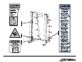
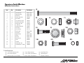
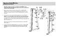
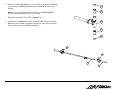
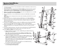
Signature Smith Machine
Owners Manual
Signature Smith Machine
Safety & Warranty
Purchasers of LIFE FITNESS products should read the Owner's Manual and all of the warning labels on the products before using them. Because these
products may be used in commercial settings, it is the purchaser's responsibility to instruct all individuals, whether users, trainers or observers, on the
proper usage of the equipment. Contact Life Fitness if you do not know how to use this equipment.
LIFE FITNESS recommends that all commercial fitness equipment be used in a supervised area. Life Fitness also recommends that the equipment be
located in an access controlled area. The extent of control is at the discretion of the owner.
SECURING EQUIPMENT: All strength equipment must be secured to the floor to a solid, level surface to stabilize and eliminate rocking or tipping over.
This must be performed by a licensed contractor.
LIFE FITNESS recommends that all users be informed of the following prior to using LIFE FITNESS equipment:
PROPER USAGE
1.
It is imperative that LIFE FITNESS equipment be used properly to avoid injury. Do not use any equipment for purposes other than those specified by the manufacturer.
2.
Keep body parts (hands, feet, hair, etc.) and clothing away from moving parts to avoid injury.
3.
Injuries may result if you exercise improperly or excessively. It is recommended that all individuals consult a physician prior to commencing
an exercise program. If at any time during exercise you feel faint, dizzy or experience pain, stop and consult your physician.
4.
When adjusting any seat, knee hold down pad, or range of motion limiter, make certain that the adjusting pin is fully engaged in the hole to
avoid injury.
CHECK FOR DAMAGED PARTS
1.
DO NOT use or permit the use of any equipment that is damaged or has worn or broken parts. For all LIFE FITNESS equipment, use only
replacement parts supplied by LIFE FITNESS.
2.
MAINTAIN LABELS AND NAMEPLATES: Do not remove labels for any reason. Labels contain important information. If unreadable or missing,
contact LIFE FITNESS for a replacement.
3.
MAINTAIN ALL EQUIPMENT: Preventative maintenance is the key to smooth operating equipment. Equipment should be inspected at regular
intervals. See the Maintenance section of this manual for recommended maintenance intervals.
4.
Ensure that any person(s) making adjustments or performing maintenance or repair of any kind is qualified to do so. LIFE FITNESS will provide
service and maintenance training at one of its facilities upon request or in the field if proper arrangements are made.
SPECIFIC OPERATING WARNINGS
1.
UNDERSTANDING THE FULL EXTENT OF EACH AND EVERY WARNING IS IMPORTANT. IF ANY WARNING IS UNCLEAR, ASK LIFE FITNESS
PERSONNEL FOR CLARIFICATION.
2.
Keep children away from strength equipment.
3.
Use only olympic style weight plates (2.0" Bore) for training weight. Only add weight up to the load limits of the unit and that can be fully
placed on the weight horn. Contact a Life Fitness representative with any questions regarding proper weights and loading.
Signature Smith Machine
Safety & Warranty
LIMITED WARRANTY
WHAT IS COVERED
This Life Fitness commercial exercise equipment (Signature Benches and Racks) is warranted to be free of all defects in material and workmanship to the
original purchaser for the specific items and duration listed:
O
10 years on structural frame
O
1 year on bearings
O
1 year on grips
O
1 year on cables and belts (if so equipped)
O
O
1 year for rust or corrosion of structural frame. Scratches or scrapes where the subsurface of the unit has been exposed must have been properly
repaired by the customer.
90 days on upholstery and any items not specified (including labor).
Life Fitness will ship to you at our expense, any repair parts covered by the warranty as stated. If the Product is deemed not repairable by Life Fitness
authorized personnel, we reserve the right to replace any part or the entire Product at our option within the stated warranty period.
WHAT IS NOT COVERED
Any failures or damage caused by unauthorized service, misuse, accident, negligence, improper assembly or installation, debris resulting from construction activities in the vicinity of the Product, any alterations or modifications made to the Product without written authorization by Life Fitness, or by failure
on your part to use, operate, and maintain the Product as set out in your Operation Manual. All terms of this warranty are void if this product is moved
beyond the continental borders of North America (excluding Hawaii) and are then subject to the terms provided by that country's authorized Life Fitness
Representative.
TRANSPORTATION & INSURANCE FOR SERVICE
If the Product or any covered part must be returned to a service facility for repairs, Life Fitness will pay all transportation and insurance charges for the first
year. You are responsible for transportation and insurance charges for year 2 and beyond.
HOW TO GET PARTS & SERVICE
Simply call Customer Support Services at (800) 351-3737 or (847) 451-0036, Monday through Friday from 8:00 a.m. to 6:00 p.m. Central Standard Time,
and tell them your name, address and the serial number of your Product. They will tell you how to get a replacement part, or, if necessary, arrange for
service where your Product is located or advise you on how and where to ship the Product for service. Before shipping:
1.
Obtain a Return Authorization Number (RA#) from Customer Support Services
2.
Securely pack your Product (use the original shipping carton, if possible)
3.
Write the RA# on the outside of the carton
4.
Insure the Product, and
5.
Include a letter explaining the defect or problem and a copy of your proof of purchase if you believe the service is covered by warranty
Life Fitness World Headquarters
Attn: CSS Help Desk
5100 N. River Rd.
Schiller Park, IL. 60176
EXCLUSIVE WARRANTY
THIS LIMITED WARRANTY IS IN LIEU OF ALL OTHER WARRANTIES OF ANY KIND EITHER EXPRESSED OR IMPLIED, INCLUDING BUT NOT LIMITED TO
THE IMPLIED WARRANTIES OF MERCHANTABILITY AND FITNESS FOR A PARTICULAR PURPOSE, AND ALL OTHER OBLIGATIONS OR LIABILITIES ON
OUR PART. We neither assume nor authorize any person to assume for us any other obligation or liability concerning the sale of this Product. Under no
circumstances shall we be liable under this warranty, or otherwise, for any damage to any person or property, including any lost profits or lost savings, for
any special, indirect, secondary, incidental or consequential damages of any nature arising out of the use of or inability to use this Product. Some states
do not allow the exclusion or limitation of implied warranties or of liability for incidental or consequential damages, so the above limitations or exclusions
may not apply to you.
CHANGES IN WARRANTY NOT AUTHORIZED
No one is authorized to change, modify or extend the terms of this limited warranty.
EFFECT OF STATE LAWS
This warranty gives you specific legal rights and you may have other rights, which vary, from state to state.
OUR PLEDGE TO YOU
Our Products are designed and manufactured to the highest standards.
We want you completely satisfied with our Products and will do everything possible under the terms of this warranty to keep you secure in knowing you
have bought the best!
Signature Smith Machine
Safety & Warranty
1. Frame Construction: Frame is constructed of mechanical quality steel purchased in mill run quantities. Frame is primarily 2 1/2" x 4 1/2" oval shaped
tubing and 5 1/4” x 3 3/4” “D” shaped tubing with 11 gauge wall thickness.
2. Frame Finish: The frames are coated with an electrostatic epoxy powder coat finish.
3. Bolts: Most hardware is metric and has a corrosion resistant finish. Grade 5 or greater in strength.
4. Hand Grips: Hand grips are an extruded 60-durometer-thermorubber compound that is non-absorbing, wear and tear resistant, and exhibits good dry
and wet frictional characteristics. The grips are retained with aluminum collars, which eliminates the tendency of the grips to slide off the handle.
5. Equipment Anchoring: All machines have holes in the feet, these allow easy anchoring to the floor. Life Fitness recommends that all machines be
anchored to the floor to minimize the possibility of tipping.
6. Liability Insurance: Certificate of insurance available upon request.
SIGNATURE SMITH MACHINE
Product #-SSM
Machine Weight:
581lbs. (263.5 kgs.)
Size:
49” D (124.5cm) x 86.6” W (220cm) x 92.8” H (235.7cm)
Live Area:
10’ L (3.0m) x 10’ W (3.0m)
Max Training Weight:
650 lbs. (309 kgs.)
Max Plate Capacity:
7 - 45 lb. plates per side; 20 lb Lift Bar = 650 lbs
6 - 25 kg. plates per side; 9 kg Lift Bar = 309 kgs
Signature Smith Machine
Assembly Instructions
Item
Qty
1
2
3
4
5
6
7
8
9
10
11
12
13
14
15
16
17
18
19
20
21
22
1
1
1
10
22
10
10
6
10
8
1
4
1
4
1
1
2
2
2
2
2
2
Description
Part Number
Left Side Frame
Right Side Frame
Back Brace
M10 X 130mm Bolt
3/8" Washer
1/4" Spacer (.82” OD)
M10 Socket Head Nut
M10 X 25mm Bolt
1" Hole Plug
M10 Hex Nylock Nut
Front Brace
Linear Bearing
Left Carriage
Snap Ring
Right Carriage
Lift Bar
Bar Stop
M10 Jam Nut
Cable
Rod End
M10 X 40mm Bolt
Rod End Spacer (.5” OD)
82942xx (Ref)
82943xx (Ref)
82949xx (Ref)
3236220
3236601
7634701
7335401
3236202
3237403
3236801
82947xx
8271101
83374xx (Ref)
3202602
83376xx (Ref)
82963xx (Ref)
82956xx (Ref)
3236901
8328401
3237901
3236205
7489402
4)
5)
6)
8)
9)
18)
21)
Tools Required:
O
O
O
7mm Allen Wrench (2X)
5mm Allen Wrench
Ratchet with 17mm Socket
O
O
O
17mm Deep Socket
17mm Open End Wrench
24mm Open End Wrench
7)
O
O
O
Snap Ring Plier
Tape Measure
Ratchet Extension
10)
22)
Signature Smith Machine
Assembly Instructions
BE SURE TO SELECT A LEVEL LOCATION FOR ASSEMBLY. THE
SIGNATURE SMITH MACHINE MUST REST LEVEL AND IN COMPLETE
CONTACT WITH THE FLOOR.
11
7
6
5
8
1. With the help of another person, erect the LEFT and RIGHT SIDE
FRAMES (1 & 2). Position the SIDE FRAMES approximately 50 inches
between the inside flat sections of the LIFT BAR RACKS (A) for ease of
assembly.
3
2. From the side, loosely assemble BACK BRACE (3) to the LEFT SIDE
FRAME (1) using three M10 x 130mm BOLTS (4), three 3/8" SAE WASHERS (5), three 1/4" SPACERS (6) and three M10 x SOCKET HEAD NUTS
(7). From the back, install three M10 X 25mm BOLTS (8), six 3/8" SAE
WASHERS (5) and three M10 HEX NYLOCK NUTS (10). Finger tighten the
BOLTS and NUTS only.
5
2
7
6
1
5
10
Repeat the procedure to assemble the BACK BRACE (3) to the RIGHT
SIDE FRAME (2).
3. Loosely assemble the FRONT BRACE (11) to the LEFT and RIGHT SIDE
FRAMES (1 & 2) using four M10 X 130mm BOLTS (4), four 3/8” SAE
WASHERS (5), four 1/4" SPACERS (6), and four M10 SOCKET HEAD
NUTS (7).
4
4. Insert two LINEAR BEARINGS (12) into the ends of the RIGHT CARRIAGE
(15), secure the LINEAR BEARINGS with one SNAP RING (14) at each
bearing.
14
12
NOTE: Leave the cardboard sleeve in the bottom LINEAR BEARING,
remove the cardboard sleeve from top bearing.
Repeat the procedure on the LEFT CARRIAGE (13).
15
5. Assemble the CARRIAGES (13 & 15) to the LIFT BAR (16) and as shown.
Make sure the LIFT BAR is inserted completely through both roller bearings located within the CARRIAGE TUBES (B).
12
14
15
13
16
B
Signature Smith Machine
Assembly Instructions
6.
Loosen the four set screws on the pre-assembled 1.25" SHAFT COLLARS (C) located at the top
of the SIDE FRAMES.
7.
With the help of another person and the LIFT BAR ASSEMBLY (D) oriented as shown, position
it near the bottom of the GUIDE RODS (E). Lift both GUIDE RODS up through the top of the
SIDE FRAMES. Hang the LIFT BAR ASSEMBLY on the third LIFT BAR RACK (A) hook.
8.
Making sure the SHAFT COLLAR and BUMPER remain above the CARRIAGE, insert one GUIDE
ROD into CARRIAGE of the LIFT BAR ASSEMBLY.
9.
E
2
1
C
Slide one BAR STOP (17) on the GUIDE ROD (E) and slide the GUIDE ROD back inside SIDE
FRAME.
NOTE: Make sure the warning label faces inward when assembling the BAR STOP (17) on the
GUIDE ROD (E)
A
10. Repeat steps 9 & 10 for to assemble remaining GUIDE ROD to the LIFT BAR ASSEMBLY.
11. Adjust the machine so the measured distance between inside faces of the LIFT BAR RACKS
(A), both top and bottom, is 48 13/16 to 49 5/16 inches (123.98 to 125.25 cm). Tighten all
BOLTS and NUTS securely.
12. Thread the one JAM NUT (18) fully onto each of the CABLE (19) ends. Thread one ROD END
(20) onto each of the CABLE ends approximately ½". DO NOT TIGHTEN JAM NUT.
13. Attach one ROD END (20) to each of the CARRIAGES using one M10 X 40mm BOLT (21), one
ROD END SPACER (22), and one M10 HEX NYLOCK NUT (10) per side. Tighten the NUTS
securely.
D
15
13
17
14. Cycle the LIFT BAR up and down. There must not be any banging of the COUNTER-WEIGHTS
located inside the large front tubes at either the top or the bottom of the cycle.
The Product MUST pass BOTH of the following criteria:
A. With the LIFT BAR at its topmost position (CARRIAGES against BUMP STOPS) both
CABLES need to be in tension.
If the cable is not tensioned, screw the loose CABLE into ROD END until the
cable is taut. Re-cycle the lift bar and recheck the cable tension. When cable is
properly tensioned, proceed to criteria B.
B. Position the LIFT BAR at its bottommost position (LIFT BAR and BAR STOPS not
engaging LIFT BAR RACKS). Be sure both BAR STOPS are resting on the SIDE
FRAMES and both CARRIAGES are resting on the BAR STOPS.
Ensure that the cable is not too tight by slight pulling down on the CABLE while
holding the LIFT BAR firmly at its bottommost position. The cable should move
slightly; approximately ¼ to ½ inch.
If the cable is too tight, unscrew the tight CABLE out of the ROD END making
sure a minimum of three threads are engaged.
C. If both above criteria cannot be satisfied,
see Counterweight Cable Adjustment.
19
18
22
20
21
10
When all of the above criteria have been met, tighten the JAM NUT (18) and continue to complete the installation.
15. Install 1" HOLE PLUGS (9) into all open bolt holes.
19
16. Cycle the machine to ensure smooth LIFT BAR operation up and down.
18
22
10
20
Counterweight Cable Adjustment
If the CABLE is still too tight after maximum ROD END adjustment, the CABLE END on the COUNTERWEIGHT side will need to be adjusted. Adjusting the CABLE END on COUNTERWEIGHT should be done in
the following manner:
21
13
1) Remove one M10 X 40mm BOLT (21), one ROD END SPACER (22), and one M10 HEX NYLOCK NUT
(10) from each of the CARRIAGES (13 & 15). Holding the ROD END (20) firmly, slowly lower the
COUNTERWEIGHT (a) until it reached bottom.
2) Remove the two M10 X 20mm BOLTS (b) from the TOP D-TUBE CAP (c) and remove the cap.
3) Remove one M10 X 50mm BOLT (d), two FLAT WASHERS (e) and one NUT (f) from the PULLEY (g)
and remove the PULLEY.
c
4) Remove the two M10 X 20mm BOLTS (h) and FLAT WASHERS (j) from the GUIDE ROD BRACKET (k)
and remove the BRACKET through the top of the machine.
k
5) Pull the CABLE until the top of the COUNTERWEIGHT (a) is just above the top of the D-TUBE.
o
Prop the COUNTERWEIGHT to prevent it from sliding into the D-TUBE.
f
a
6) Loosen the JAM NUT (n) on top of the COUNTERWEIGHT (a) and thread the CABLE END (o) in (if
CABLE is too long) or out (if CABLE is too short). Retighten the JAM NUT.
8) Reassemble all removed components in reverse order of removal. Tighten all bolts and nuts
securely.
e
n
CAUTION: DO NOT PULL COUNTERWEIGHT COMPETELY OFF OF GUIDE RODS (m).
7) Guide the COUNTERWEIGHT (a) down the GUIDE RODS (m) until it reaches the bottom.
b
j
e
h
d
m
9) Return to Step 13 and continue to confirm criteria is met.
g
Signature Smith Machine
Maintenance
ONCE A WEEK
Visually inspect all hardware, including jam nuts, for loosening, tampering or wear.
Check condition of hand grips.
O
O
ONCE A MONTH
Inspect hardware and tighten any bolts or nuts that may have loosened during use.
Clean Guide Rods with Break-Free® on a cotton cloth wipe off old residue. Clean visible sides of linear bearings on carriages.
Check Jam Nuts on Rod Ends for tightness.
O
O
O
ACTION
DAILY
MONTHLY
BI-ANNUALLY
AS NEEDED
CLEAN
Hand Grips
X
Guide Rods
X
INSPECT
Hardware
X
Frame
X
Hand Grips
X
Jam Nuts
X
CLEAN
O
O
O
Wax Frames with standard, non-abrasive wax finish.
Hand grips with mild soap and water.
Guide Rods with cotton cloth and Break-Free® (SK50-P0005-0000).
INSPECT
O
O
O
O
Hardware should be checked for looseness. Tighten as required using metric tools.
Frames should be inspected for wear or damage.
Hand grips should be checked for wear or damage.
All paint chips should be filled immediately with touch-up paint.
NOTE: Use polishing compound (such as car wax) to clean and remove shoe scuffs from frame surfaces as necessary.
NOTE: For parts and service call Customer Support Services at (800)351-3737 or (847)451-0036, Monday through Friday 8:00 a.m. to 6:00 p.m. Central Standard Time.
Please have available your name, address and serial number of your product.
©
2007 Life Fitness, a division of Brunswick Corporation. All rights reserved.
Life Fitness is a registered trademark of Brunswick Corporation.
SSM
10/12/07
8376701 RevA-1