1
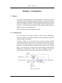
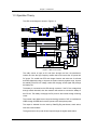
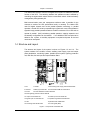
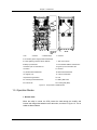
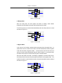
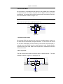
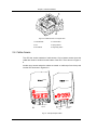
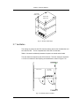
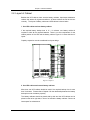
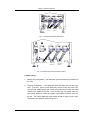
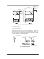
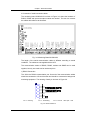
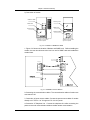
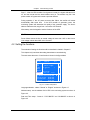
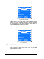
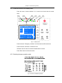
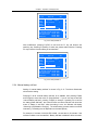
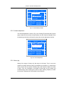
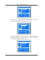
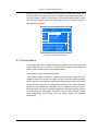
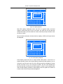
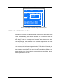
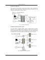
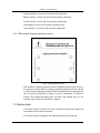
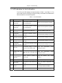
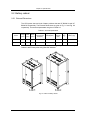
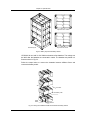
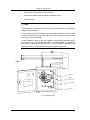
Chapter 4 Commissioning of UPS
Chapter 4 Commissioning of UPS
4.1 Startup Procedure
4.1.1 Explanation of Circuit Breakers
From the layout of Figure 1-3 and Figure 1-4, the startup of UPS has connections
with the following circuit breakers
Q1 : Connects rectifier to Utility source
Q2 : Connects bypass to Utility source
Q5 : Connects UPS output to the Load
Q3BP : Connects bypass input source to the load switch
QF1 : Battery Circuit Breaker
4.1.2 Startup
All the circuit breakers of the UPS should be switched off and phase rotation correct.
The battery cables are connected correctly. Q1 and Q2 are connected to utility.
Note
Before startup, do not connect the load
The UPS should be started up according to the following procedures:
Step 1 : Switch on Q2 and Q5. The power source indicator on the panel turns on
and the LCD displays information during startup.
Step 2 : Switch on Q1 and QF1. The sound of the relay closing should be heard.
After 2 secs, the main contactor closes. The rectifier starts after the soft start relay
opens. The rectifier indicator flashes several times and the rectifier enters normal
operation states after about 10 secs.
Step 3 : The battery input contactor closes automatically after the DC bus reaches
the pre-set value. The battery indicator illuminates before the battery contactor
closes and it turns off after the contactor closes.
Step 4 : Press the button “inverter start” for two seconds. The inverter will start up
and enters normal operating state when the inverter indicator flash.
37