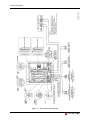
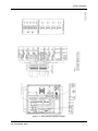
1
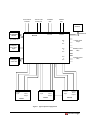
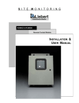
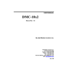
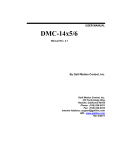
(19,5210(17$/ý&21752/
$XWRð&KDQJHRYHUý&RQWUROOHU
TABLE OF CONTENTS
SECTION 1: INTRODUCTION ......................................................................................................... 1
SECTION 2: START UP....................................................................................................................... 3
SECTION 3: OPERATION .................................................................................................................. 5
Local ..............................................................................................................................................................................5
Sequencing Status Screens.....................................................................................................................................5
Password Screen ....................................................................................................................................................6
Main Menu ............................................................................................................................................................6
Status Sub-menu..........................................................................................................................................6
Set Options Sub-menu.................................................................................................................................8
Alarm Sub-menu .......................................................................................................................................13
Set Clock Sub-menu..................................................................................................................................14
Override 14
Terminal ......................................................................................................................................................................16
Main Menu ..........................................................................................................................................................16
Status Screen .............................................................................................................................................17
Setup Zones/Units Options........................................................................................................................18
Alarms Review and Alarms Clear .............................................................................................................21
Set Clock...................................................................................................................................................21
Override A Unit ........................................................................................................................................22
Set Modem Options...................................................................................................................................23
Setup Temp/Humid Options......................................................................................................................24
Setup Standby Unit Options ......................................................................................................................25
Display SS Alarm Block ...........................................................................................................................26
Set New Password.....................................................................................................................................26
SECTION 4: GLOSSARY OF CONTROL FUNCTIONS .......................................................... 27
SECTION 5: INSTALLATION .......................................................................................................... 37
Liebert RAC2-8 • i
TABLE OF FIGURES
Figure i.
Figure 2–1.
Figure 5–1.
Figure 5–2.
Figure 5–3.
Figure 5–4.
Typical System Configuration..........................................................................................................iii
Local Control Panel ..........................................................................................................................3
RAC2-8 Dimensional Enclosure Diagram ......................................................................................39
RAC2-8 Component Arrangement ..................................................................................................40
RAC2-8 Connection Diagram .........................................................................................................45
RAC2-8 Switch and Jumper Settings ..............................................................................................42
ii • User Manual (9/97)
Power Source
120 VAC
Aux Pwr Out
24 VAC, 2A
Terminal
Port
Modem
Port
SiteScan
Liebert
Temp/Humid
Module
EIA-232
RAC2-8
(p/n THS28-xx)
Emergency
Power Oper.
Input
Emergency
Power Off
Control
Input
Common
Alarm
Output
UNIT 1
Control
Input
Common
Alarm
Output
UNIT 2
EIA-422
Twisted Pair
EIA-232
N.O.
C
N.C.
Common Alarm
Output
N.O.
C
N.C.
Humidity Lockout
Relay
N.O.
C
N.C.
Optional Lockout
Relay
Control
Input
Common
Alarm
Output
UNIT 8
Figure i. Typical System Configuration
Liebert RAC2-8 • iii
Section 1: Introduction
See SECTION 5 —
INSTALLATION for special
instructions when using the RAC2-8
with Liebert mini-MATE, mini-MATE
Plus, and DataMate environmental
control systems.
The Liebert RAC2-8 remotely controls from two to eight environmental
units. Each unit is assigned to a Zone (room) from 1 to 4. In Zone 1, the
largest room, the temperature and humidity can be monitored. The
common alarm output from each unit is monitored and annunciated by
the RAC2-8. Up to 20 system alarms can be stored with time and date
stamp. All alarms are latching and must be manually cleared.
The most important control functions are Autochangeover,
Autosequencing, and Standby Testing. Each unit can be assigned a
Running or Standby status.
Autochangeover turns on a Standby unit if a Running unit in the same
zone has an alarm. The Running unit (with alarm) will be turned off if
that control option is selected. Each unit will return to its previous
status when the alarm is manually cleared.
Autosequencing balances unit run-times by changing Standby units to
Running (and Running units to Standby) at programmed time intervals.
Standby Testing turns on Standby units at programmed intervals to test
their operation. Note that Autosequencing and Standby Testing cannot
both be selected at the same time.
Other control functions include Manual Override, Emergency Power
Operation, Power Failure Mode, Password, and Programmable Delays.
Refer to SECTION 4 — GLOSSARY OF CONTROL FUNCTIONS
for more details.
System outputs include Humidity Lockout Relay, Optional Control
Lockout Relay, and Common Alarm. Communication ports are
EIA-232 for terminal or printer, a modem port, and a proprietary
EIA-422 port for communication to a Liebert SiteScan monitoring
system.
The RAC2-8 can be operated locally from the built-in control panel or
remotely from an optional terminal (EIA-232 communication). This
manual shows examples of several typical display screens during both
local and remote operation.
Liebert RAC2-8 • 1
Section 2: Start Up
To start up the RAC2-8:
1. Mount unit to wall.
2. Connect cables.
3. Set switches and jumpers on circuit boards as required for your
application. Refer to instructions and illustrations in SECTION 5
— INSTALLATION.
4. Make user programmable selections from the local control panel or
from an optional remote terminal. Refer to SECTION 4 —
GLOSSARY OF CONTROL FUNCTIONS and SECTION 3 —
OPERATION.
5. Apply power to the unit. Note that the ON/OFF switch is inside the
enclosure.
Figure 2–1. Local Control Panel
Liebert RAC2-8 • 3
4 • User Manual (9/97)
Section 3: Operation
This chapter describes how to use the RAC2-8.
Local
The following screens are displayed at the LCD display built into the
RAC2-8 unit control panel.
Refer to SECTION 4 —
GLOSSARY OF CONTROL FUNCTIONS for more details.
Sequencing Status Screens
With power ON, the following status screens are displayed in sequence.
LIEBERT RAC2-8
TEMP 71.8°F HUM 47%
MO 07-15-96 13:26:55
NO ALARMS PRESENT
STATUS ZONE 1
01-R 02-S
A=ALM S=STBY R=RUN
STATUS ZONE 2
03-R 04-S
A=ALM S=STBY R=RUN
STATUS ZONE 3
05-R 06-S
A=ALM S=STBY R=RUN
STATUS ZONE 4
07-R 08-S
A=ALM S=STBY R=RUN
Liebert RAC2-8 • 5
Section 3: Operation
Sequencing Status Screens (cont’d.)
AUTO SEQUENCING ON
DAY 06 OF 15 <00:00>
TEMP STAGING OFF
Each screen is automatically displayed for 3 seconds.
xx is the number of alarms recorded
since alarm history was last cleared.
See Alarm submenu.
These functions cannot both be ON
at the same time. Select the function
required for your installation.
To control the display of the status screens, you can press the
Hold/Sequence button to hold a screen and to manually step through the
screens. Press C to resume automatic sequencing. The system returns to
the Sequencing Status Screens if no control keys have been pressed
during a two minute period.
If alarms are present, the last line of the first screen displayed above
reads “ALARMS PRESENT - xx.” Alarm screens are displayed next in
the status sequence. Up to 20 alarms can be displayed, 5 screens of 4
alarms each. Alarms are stored in a First In First Out (FIFO) sequence.
Select either Auto Sequencing or Standby Testing from the Set Options
Sub-menu.
Password Screen
If the Password function is enabled, you must enter the valid password
to access the RAC2-8 Main Menu. At the Enter Password screen, type
the established password:
ENTER PASSWORD
>
Units are shipped from the factory with the Password function disabled.
To enable the Password function, press the MENU button to display the
Main Menu, then press 2 SETUP. Follow the instructions on page 12 to
Set Password.
Main Menu
Press the Menu button to display the Main Menu:
MAIN
1.
3.
5.
MENU
STATUS
ALARMS
OVERRIDE
2.
4.
6.
SETUP
SET CLOCK
EXIT
Press 9 to display RAC2-8 revision code and date.
Status Sub-menu
From the Main Menu, press 1. STATUS to display the Status Submenu:
6 • User Manual (9/97)
Section 3: Operation
STATUS MENU
1.
UNITS
3.
A-DELAY
5.
H-DELAY
2.
4.
6.
T/H
R-DELAY
RETURN
1. UNITS
From the Status Sub-menu, press 1. UNITS to display the Unit Status
menu:
UNIT STATUS
01-R 02-S 03-R 04-S
05-R 06-S 07-R 08-S
A=ALM S=STBY R=RUN
2. T/H
From the Status Sub-menu, press 2. T/H to display the
Temperature/Humidity screen:
TEMP 71.8°F HUM 47%
STAGING OFF
PUSH CLEAR TO RETURN
3. A-DELAY
From the Status Sub-menu, press 3. A-DELAY to display the Alarm
Delays screen:
ALARM DELAYS
0000 0000 0000 0000
0000 0000 0000 0000
PUSH CLEAR TO RETURN
Liebert RAC2-8 • 7
Section 3: Operation
Status Sub-menu (cont’d)
The Alarm Delays screen indicates the time in seconds of an active
delay on each unit. Active alarm delays count up while the condition is
present and count down if the condition is cleared before the Alarm
Delay time elapses.
4. R-DELAY
From the Status Sub-menu, press 4. R-DELAY to display the Restart
Delays screen:
RESTART DELAYS
0000 0000 0000 0000
0000 0000 0000 0000
PUSH CLEAR TO RETURN
The Restart Delays screen indicates the time in seconds of an active
restart delay on each unit.
5. H-DELAY
From the Status Sub-menu, press 5. H-DELAY to display the Hold
Delay screen:
HOLD DELAY = 0000
PUSH CLEAR TO RETURN
Hold Delay applies to the system rather than to each unit. Therefore,
only one number is displayed. This display indicates the time in seconds
of an active Hold Delay.
Set Options Sub-menu
From the Main Menu, press 2. SETUP to display the Set Options
Menu:
SET OPTIONS MENU
1.
UNITS
2.
3.
TEMP/HUM
4.
5.
PASSWORD
6.
DELAYS
STANDBY
RETURN
1. UNITS
From the Set Options Sub-menu, press 1. UNITS to display the Set
Units menu:
Set Options Sub-menu (cont’d)
SET UNITS MENU
1.
ZONES/UNITS
2.
EMER.OP
3.
4.
SHUTDOWN
5.
8 • User Manual (9/97)
LABELS
RETURN
Section 3: Operation
Note that the Clear button will not
allow you to exit these screens until
all selections have been made.
From the Set Units menu, select 1. ZONES/UNITS to select the number
of zones, number of units in each zone, and operating status of each
unit. Complete all of these selections before exiting this setup
function.
When you press 1. ZONES/UNITS, the RAC2-8 sequences through the
screens you must complete.
SET NUMBER OF ZONES
RANGE 1-4 <4> >_
PUSH ENTER FOR NEXT
SET NUMBER OF UNITS
ZONE 1 <2> >_
PUSH ENTER FOR NEXT
Set Number of Units screen will be iterated for each zone selected (up
to 4).
The RAC2-8 then displays the Set Status screen for Zone 1:
SET STATUS ZONE 1
01-R 02-S
1=RUN O=STBY E=NEXT
Set Status screen is iterated for each zone selected. Press 1, or 0 to set
the status. After you have selected the operating status of units in your
last zone, Press E to return to the Set Units Menu.
From the Set Units menu, press 2. EMER OP. to display the Set
Emergency Operating Units ON screen:
SET EMRG.OP UNITS ON
01-R 02-0 03-0 04-R
05-0 06-R 07-0 08-0
1=RUN O=OFF E=NEXT
Set Options Sub-menu (cont’d)
Beginning with unit 01, set each unit's emergency operating status.
Press E to continue to the next unit. When you have configured the last
unit, the RAC2-8 returns to the Set Units menu.
From the Set Units menu, press 3. LABELS to display the Assign
Labels to Unit screen:
ASSIGN LABEL TO UNIT
1-01 2-02 3-03 4-04
5-05 6-06 7-07 8-08
PUSH ENTER FOR NEXT
Beginning with unit 01, assign a label to each unit. You can use two
numbers, two letters, or a two-character number/letter label. Press E to
continue to the next unit. When you have configured the last unit, the
RAC2-8 returns to the Set Units menu.
Liebert RAC2-8 • 9
Section 3: Operation
From the Set Units menu, press 4. SHUTDOWN to display the
Shutdown on Alarm screen:
SHUTDOWN ON ALARM
01-Y 02-Y 03-Y 04-Y
05-Y 06-Y 07-Y 08-Y
1=YES O=NO E=NEXT
Beginning with unit 01, indicate 1 (Yes) or 0 (No) if the unit should
shut down on alarm. When you have selected the shutdown status for
the last unit, the RAC2-8 displays the Set Units menu.
When you have configured the delays, from the Set Units menu, press 5
to return to the Set Options Menu.
2. DELAYS
SECTION 4 — GLOSSARY OF
CONTROL FUNCTIONS
includes a functional description
of each delay.
From the Set Options Sub-menu, press 2. DELAYS to display the Set
Delays menu:
SET
1.
3.
5.
DELAYS MENU
ALARM
2.HOLD
UNIT RESTART
RETURN
From the Set Delays menu, press 1. ALARM to configure the Alarm
Delay:
Set Options Sub-menu (cont’d)
ENTER ALARM DELAY
<10.0> XX.X MINUTES
THEN PUSH ENTER
PUSH CLEAR TO RETURN
Enter the desired time for the alarm delay. The default is 10 minutes.
Press E to accept the new delay, then press C to return to the Set Delays
menu.
From the Set Delays menu, press 2. HOLD to configure the Hold
Delay:
ENTER HOLD DELAY
<10.0> XX.X MINUTES
THEN PUSH ENTER
PUSH CLEAR TO RETURN
Enter the desired time for the hold delay. The default is 10 minutes.
Press E to accept the new delay, then press C to return to the Set Delays
menu.
10 • User Manual (9/97)
Section 3: Operation
From the Set Delays menu, press 3. UNIT RESTART to configure the
restart delay:
ENTER RESTART DELAY
<00.1> XX.X MINUTES
THEN PUSH ENTER
PUSH CLEAR TO RETURN
Enter the desired time for the restart delay. The default is 0.1 minutes.
Press Enter to accept the new delay, then press C to return to the Set
Delays menu.
When you have configured the delays, from the Set Delays menu, press
5 to return to the Set Options Sub-menu.
3. TEMP/HUM
From the Set Options Sub-menu, press 3. TEMP/HUM to display the
Set T/H menu:
SET T/H MENU
1.T/H ALARM POINTS
2.TEMP. STAGING
3.F/C
4.LOCK
5.EXIT
Set Options Sub-menu (cont’d)
The Set Temp/Hum and Temp Staging functions apply only to Zone 1.
The temperature and humidity inputs are from a separate remote sensor,
not from an operating unit.
From the Set T/H menu, press 1. T/H ALARM POINTS:
TEMP HI>75 LOW>65
HUM HI>60 LOW>40
<RANGE 50-90> 00=off
E=NEXT C=RETURN
Beginning with Temp Hi, enter the temperature and humidity alarm
points. The third line displays the range for the alarm limit you are
selecting. Press E to continue to the next point. When you have set all
points, press C to return to the Set T/H menu.
From the T/H menu, press 2. TEMP. STAGING:
STAGING ON/OFF
NORMAL TEMP
SENSITIVITY
1=ON
O=OFF
>OFF
>72
>02
E=NEXT
Beginning with Staging ON/OFF, configure each parameter. Press E at
the last parameter to return to the T/H menu.
From the T/H menu, press 3. F/C to configure degrees in Fahrenheit or
Celsius:
SELECT F/C <F>
Liebert RAC2-8 • 11
Section 3: Operation
1. F
2. C
5. RETURN
From the T/H menu, press 4. LOCK to configure the optional Humidity
Lockout feature:
HUMIDITY LOCKOUT
SET HI>00 LOW>00
(RANGE 20-80) 00=OFF
E=NEXT C=RETURN
Refer to SECTION 4 — GLOSSARY OF CONTROL FUNCTIONS
for details on the Humidity Lockout feature.
Set Options Sub-menu (cont’d)
4. STANDBY
From the Set Options Sub-menu, press 4. STANDBY to display the
Standby Options menu:
STANDBY OPTIONS MENU
1. AUTO SEQUENCE UNIT
2. AUTO STANDBY TEST
5. RETURN
From the Standby Options menu, select Auto Sequencing, Standby
Testing, or neither. These functions cannot both be active (ON) at the
same time.
Select the desired function. If you select 1. AUTO SEQUENCE UNIT,
you must also configure a schedule for your installation:
AUTO SEQUENCING ON
EVERY <0-99> XX DAYS
AT TIME 00:00
00=OFF E=NEXT C=RTN
5. PASSWORD
From the Set Options Sub-menu, press 5. PASSWORD to display the
Set Password menu:
SET PASSWORD MENU
1. NEW PASSWORD
5. RETURN
The Password function provides security to the RAC2-8 so that only
authorized personnel can make Setup changes to the system.
12 • User Manual (9/97)
Section 3: Operation
Press 1. NEW PASSWORD to set a new four-digit password for the
system, then follow the instruction on the screens:
ENTER NEW PASSWORD
>
THEN PUSH ENTER
PUSH CLEAR TO RETURN
Enter “0000” to disable the Password function.
Set Options Sub-menu (cont’d)
CONFIRM NEW PASSWORD
>
THEN PUSH ENTER
When you have finished configuring the Password, Press E to return to
the Main Menu.
Alarm Sub-menu
From the Main Menu, press 3. ALARMS to display the Alarm Submenu:
ALARM MENU
1. ALARM REVIEW
2. CLEAR ALARMS
3. RETURN
Press 1 to review all alarms. The RAC2-8 can store up to 20 alarms in
the alarm memory buffer in a First-In-First-Out (FIFO) sequence.
For each alarm, the review screen displays the alarm number, total
number of alarms, date and time stamp, and the alarm message:
ALARM #01/05 ZONE #1
@ 07-15-96 15:20:42
UNIT XX COMMON ALARM
PUSH ENTER FOR NEXT
If there are no alarms, the screen reads "NO ALARMS PRESENT."
NO ALARMS PRESENT
PUSH CLEAR TO RETURN
Press 2. to display the CLEAR ALARMS screen, then press 1 again to
clear all alarms:
CLEAR ALARMS
1. CLEAR ALL ALARMS
2. RETURN
Liebert RAC2-8 • 13
Section 3: Operation
Set Clock Sub-menu
From the Main Menu, press 4. SET CLOCK to display the Set Clock
Sub-menu:
SET CLOCK MENU
1. DATE
2. TIME
3. DAY OF WEEK
4. RETURN
1. DATE
Press 1 to set the system date:
MO 07-15-96 15:12:34
SET DATE MM-DD-YY
THEN PUSH ENTER
PUSH CLEAR TO RETURN
The first line displays the current system day, date, and time. Enter the
new date, then press E to return to the Set Clock Sub-menu.
2. TIME
Press 2 to set the system time:
MO 07-15-96 15:12:34
SET TIME HH:MM:SS
THEN PUSH ENTER
PUSH CLEAR TO RETURN
The first line displays the current system day, date, and time. Enter the
new time, then press E to return to the Set Clock Sub-menu.
3. DAY OF WEEK
Press 3 to set the system day of the week:
SET DAY >MON
1-SUN 2-MON 3-TUE
4-WED 5-THU 6-FRI
7-SAT 8-RETURN
Enter the appropriate number for the desired day. When finished, press
8 to return to the Main Menu.
Override Submenu
From the Main Menu, press 5. OVERRIDE to display the Override a
Unit screen:
OVERRIDE A UNIT
ENTER UNIT #
THEN PUSH ENTER
PUSH CLEAR TO RETURN
14 • User Manual (9/97)
Section 3: Operation
The Override function lets you manually force a unit ON or OFF, or to
restore a forced unit to the normal control of the RAC2-8 system. The
Override function acts immediately, ignoring the Hold Delay. An
override message with time stamp is entered in the Alarm memory
buffer. The Alarm light remains on while any unit is in an Override
mode.
To override a unit, enter the two digit label assigned to the unit, then
press Enter:
UNIT 01 FORCED ON
2. FORCE OFF
3. RESTORE
4. RETURN
Select the desired override option.
When finished, press 4 to return to the Main Menu.
Liebert RAC2-8 • 15
Section 3: Operation
Terminal
A local terminal can be connected directly by an EIA-232
communication cable to the RAC2-8, or a remote terminal can be
connected through modems. All of the status information and control
functions available at the RAC2-8 local display are available from the
terminal. An additional function available at the terminal is Set Modem.
The terminal also displays a status message with time and date stamp
whenever a unit changes status (OFF or ON). These status messages
will be printed if a printer (instead of a terminal) is connected to the
EIA-232 port. Once each 24 hours (at midnight) the terminal checks its
ability to communicate with the RAC2-8 and writes a Comm Check
message.
A terminal connected to an active RAC2-8 displays alarm and status
messages when they occur. The prompt then asks the operator to press
<space>, <S>, or <A>.
07-15-96
12:14:12
On UNIT 03 FORCED ON
07-15-96
12:14:19
On UNIT 63 RESTORED Menu
Exited - Press <space> to Enter Menu, <S> for
Status, <A> for Alarms
<space> displays Main Menu after a password is entered.
<S> displays present status.
<A> displays a list of alarms (up to 20).
LOG ON:
is the prompt to enter a password. This prompt is also displayed when
the system is accessed through a modem.
Main Menu
The Main Menu is displayed on a terminal as shown below:
RAC2-8 MAIN MENU
1. Status
2. Setup Zones/Units Options Menu
3. Alarms Review
4. Alarms Clear
5. Set Clock
6. Override a Unit
7. Set Modem Options
8. Setup Temp/Humid Options Menu
9. Setup Standby Unit Options
A. Display SS Alarm Block
P. Set New Password
X. Exit
Main Menu (cont’d)
When you make a program selection
from the terminal, the screen is
displayed again with the new
value(s).
16 • User Manual (9/97)
Each Main Menu item has a corresponding screen that lets you
configure the system parameters. Each screen is shown in the following
sections.
Section 3: Operation
Status Screen
The Status screen is displayed by pressing the <S> key (no password
required) or by pressing the <1> key from the Main Menu.
RAC2-8 STATUS - 07-16-96 09:22:13
Temperature = 70.6°F
Humidity = --%
Modem = OFF
UNIT
LABEL
ZONE
EMRG.PWR SHUTDOWN
STATUS
----------------------------------------------------01
01
1
RY
RUNNING
02
02
1
RN
RUNNING
03
03
1
RN
RUNNING
04
04
1
RN
STANDBY
05
05
0
ON
UNPROGRAMMED
06
06
0
RN
UNPROGRAMMED
07
07
0
RN
UNPROGRAMMED
08
08
0
RN
UNPROGRAMMED
Alarm Delay
Hold Delay
Auto Restart Delay
= 10.0
= 10.0
= 00.1
High Temperature Alarm
High Humidity Alarm
High Humidity Lockout
= 00
= 00
= 00
AUTO SEQUENCING
STANDBY TESTING
DAY 01 of 59 @ 00:00
Temperature Staging
= ON
= OFF
Low Temperature Alarm
Low Humidity Alarm = 00
Low Humidity Lockout
= 00
= 00
= OFF
NO ALARMS PRESENT
Press menu selection (1-X) key <ESC to display Main Menu>
Configure the parameters as desired.
Liebert RAC2-8 • 17
Section 3: Operation
Setup Zones/Units Options
Press 2 from the Main Menu to display the Set Options menu. The
following screens show the terminal display that enables you to
configure the Options menu items.
NUMBER OF ZONES/NUMBER OF UNITS PER ZONE
RAC2-8 MAIN MENU
SET OPTIONS MENU
1. Set Number of Zones
2. Set Number of Units per Zone
3. Set Unit Status
4. Set Emergency Power Units
5. Set Unit Shutdown on Alarm
6. Set Unit Labels
7. Set Alarm Delay
8. Set Hold Delay
9. Set Restart Delay
<ESC> TO EXIT
CURRENT NUMBER OF ZONES = 1
ENTER NEW NUMBER (1-4) <ESC to quit> >2
CURRENT NUMBER OF ZONES = 2
ENTER NEW NUMBER (1-4) <ESC to quit> >
SET OPTIONS MENU
** SET NUMBER OF UNITS PER ZONE **
ZONE 1 = 4 UNITS
ZONE 2 = 0 UNITS
ZONE 3 = UNPROGRAMMED
ZONE 4 = UNPROGRAMMED
ENTER ZONE (1 - 2) <ESC to quit> >2
ZONE 2 has 0 UNITS
ENTER NEW NUMBER (2-8) <ESC to quit> >2
** SET NUMBER OF UNITS PER ZONE **
ZONE 1 = 4 UNITS
ZONE 2 = 2 UNITS
ZONE 3 = UNPROGRAMMED
ZONE 4 = UNPROGRAMMED
ENTER ZONE (1 - 2) <ESC to quit> >
SET OPTIONS MENU
Setup Zones/Units Options (cont’d)
Configure the number of zones and number of units as desired.
UNIT STATUS
SET OPTIONS MENU
** SET UNIT STATUS **
UNIT
LABEL ZONE
STATUS
----------------------------------------------1
18 • User Manual (9/97)
01
1
RUNNING
Section 3: Operation
2
02
1
RUNNING
3
03
1
RUNNING
4
04
1
STANDBY
5
05
2
RUNNING
6
06
2
STANDBY
7
07
0
UNPROGRAMMED
8
08
0
UNPROGRAMMED
PRESS UNIT (1-8) KEY <ESC TO QUIT> 3
PRESS A KEY (R=RUN or S=STANDBY) <ESC to quit> >07-17-96
00:24:29 UNIT 03 SHUTDOWN
** SET UNIT STATUS **
UNIT
LABEL ZONE
STATUS
----------------------------------------------1
01
1
RUNNING
2
02
1
RUNNING
3
03
1
STANDBY
4
04
1
STANDBY
5
05
2
RUNNING
6
06
2
STANDBY
7
07
0
UNPROGRAMMED
8
08
0
UNPROGRAMMED
PRESS UNIT (1-8) KEY <ESC TO QUIT>
Setup Zones/Units Options (cont’d)
EMERGENCY POWER UNITS
SET OPTIONS MENU
The number of Running units can be
reduced to limit the load on the
backup power source (a UPS system
or a standby generator).
** SET EMERGENCY POWER UNITS **
UNIT
LABEL ZONE EMERGENCY POWER
---------------------------------------1
01
1
RUN
2
02
1
RUN
3
03
1
RUN
4
04
1
RUN
5
05
2
OFF
6
06
2
RUN
7
07
0
RUN
8
08
0
RUN
PRESS UNIT (1-8) KEY <ESC TO QUIT> 1
Unit Shutdown on Alarm
When an alarm occurs in a Running unit, the Standby unit in the same
zone will be turned ON. The unit in alarm will remain ON unless it is
programmed to be turned OFF (Yes).
SET OPTIONS MENU
** SET UNIT SHUTDOWN ON ALARM **
UNIT LABEL ZONE SHUTDOWN
-----------------------------------------1
01
1
YES
2
02
1
NO
3
03
1
NO
4
04
1
NO
5
05
2
NO
6
06
2
NO
7
07
0
NO
Liebert RAC2-8 • 19
Section 3: Operation
08
0 <ESC
NOTO QUIT> 1
PRESS 8
UNIT (1-8)
KEY
20 • User Manual (9/97)
Section 3: Operation
Unit Labels
The RAC2-8 will accept any 2 digit label if you prefer something other
than 01 through 08.
SET OPTIONS MENU
** SET UNIT LABEL **
UNIT LABEL
------------1
01
2
02
3
03
4
04
5
05
6
06
7
07
8
08
PRESS UNIT (1-8) KEY <ESC TO QUIT> 1
Alarms Review and Alarms Clear
Press 3 or 4 from the Main Menu to access the Alarms Review and
Alarms Clear screens. The RAC2-8 can store and display up to 20
Alarms with time and date stamp. All alarms are latching and must be
cleared manually.
RAC2-8 MAIN MENU
NO ALARMS PRESENT
07-18-96 00:25:47 ALARMS CLEARED
Set Clock
Press 5 from the Main Menu to display the Set Clock screen.
RAC2-8 MAIN MENU
Current Date/Time is THU 07-18-96 00:25:50
Enter New Date/Time (DOW MM-DD-YY HH:MM) MON 07-22-96 09:15
Current Date/Time is MON 07-22-96 09:15:00
Set the new date and time as desired.
Liebert RAC2-8 • 21
Section 3: Operation
Override A Unit
Press 6 from the Main Menu to display the Override a Unit screen. A
unit can be Forced ON, Forced OFF, or Restored to automatic control.
RAC2-8 MAIN MENU
** OVERRIDE A UNIT **
UNIT LABEL STATUS
-----------------------------------------1
01
RUNNING
2
02
RUNNING
3
03
STANDBY
4
04
STANDBY
5
05
RUNNING
6
06
STANDBY
7
07
UNPROGRAMMED
8
08
UNPROGRAMMED
PRESS UNIT (1-8) KEY <ESC TO QUIT> 3
1.
FORCE ON
2.
FORCE OFF
3.
RESTORE
07-22-96 12:14:12 On UNIT 03 FORCED ON
** OVERRIDE A UNIT **
UNIT LABEL STATUS
-----------------------------------------1
01
RUNNING
2
02
RUNNING
3
03
FORCED ON
4
04
STANDBY
5
05
RUNNING
6
06
STANDBY
7
07
UNPROGRAMMED
8
08
UNPROGRAMMED
PRESS UNIT (1-8) KEY <ESC TO QUIT> 3
1. FORCE ON
2. FORCE OFF
3. RESTORE
07-22-96 12:14:19 On UNIT 03 RESTORED
22 • User Manual (9/97)
Section 3: Operation
Set Modem Options
Press 7 from the Main Menu to display the Set Modem Options screen.
RAC2-8 MAIN MENU
** SET MODEM OPTIONS **
1. Phone Number
=
2. Site ID
=
3. Dial Prefix
= ATE1X4DT
4. Redial Interval (minutes) = 01
5. Redial Tries (--- = Forever)
6. Modem Messages Y/N
= No
<ESC> TO EXIT
Phone Number = 7944
** SET MODEM OPTIONS **
1. Phone Number
= 7944
2. Site ID
=
3. Dial Prefix
= ATE1X4DT
4. Redial Interval (minutes) = 01
S. Redial Tries (--- = Forever)
6. Modem Messages Y/N
= No
<ESC> TO EXIT
Site ID
= AIR ROOM #1
= 03
= 03
These parameters are unique to terminal operation.
The Site ID (up to 20 characters) is user selected to identify a specific
facility. The Dial Prefix activates the modem and therefore must be
compatible with the modem. The Dial Prefix is factory set. Do not
change the Dial Prefix without consulting the modem user’s
manual. Modem messages describe modem activity such as No
Answer, Line Busy, Redial in 3 Minutes, etc. Select Yes if you want
these messages displayed at the terminal.
Make modem baud rate selection by setting DIP Switch 2-1 inside the
RAC2-8 enclosure. Refer to Figure 5–4 in SECTION 5 —
INSTALLATION. Set Switch 2-2 to ON (down) if you are using a
leased line.
The Modem must be Hayes or Hayes compatible. Switches inside the
modem should remain factory set except the following which are user
selectable.
Liebert RAC2-8 • 23
Section 3: Operation
Set Modem Options (cont’d)
Hang up on DTR on-off transition
Model 1200:
SW1 up and SW10 down
Model 2400:
&D3
Track status of carrier detect
Model 1200:
SW6 up
Model 2400:
&C1
Enable Auto-answer
Model 1200:
SW5 up
Model 2400:
S0=1
Setup Temp/Humid Options
Press 8 from the Main Menu to display the Setup Temp/Humid Options
screen.
RAC2-8 MAIN MENU
** SET TEMP/HUMIDITY OPTIONS **
1. High Temperature Alarm = 00
2. Low Temperature Alarm = 00
3. High Humidity Alarm
= 00
4. Low Humidity Alarm
= 00
5. Temperature Staging
= OFF
6. Normal Temperature
= 70
7. Sensitivity
= 02
8. Temp Display (F/C)
= F
9. High Humidity Lockout = 60
A. Low Humidity Lockout
= 00
<ESC> TO EXIT
High Temperature Alarm = (50-90) >80
** SET TEMP/HUMIDITY OPTIONS **
1. High Temperature Alarm = 80
2. Low Temperature Alarm = 00
3. High Humidity Alarm
= 00
4. Low Humidity Alarm
= 00
5. Temperature Staging
= OFF
6. Normal Temperature
= 70
7. Sensitivity
= 02
8. Temp Display (F/C)
= F
9. High Humidity Lockout = 60
A. Low Humidity Lockout
= 00
<ESC> TO EXIT
Temperature Staging
= (ENTER 1 for ON, 0 for OFF) >ON
Setup Temp/Humid Options (cont’d)
Temperature and humidity options apply to Zone 1. The system inputs
come from a remote temp/hum sensor. Each alarm can be disabled by
entering 00 as the alarm trip-point. Temperature Staging turns on a
Standby unit when the room temperature exceeds the Normal
Temperature by the number of degrees entered in Sensitivity. Also note
that temperature can be displayed in either degrees F or degrees C.
24 • User Manual (9/97)
Section 3: Operation
Setup Standby Unit Options
Press 9 from the Main Menu to display the Set Standby Unit Options
screen:
RAC2-8 MAIN MENU
** SET STANDBY UNIT OPTIONS **
1. Auto Sequencing
= ON
2. Standby Testing
= OFF
3. Day Interval
= 89
4. At Time
= 07:00
<ESC> TO EXIT
Auto Sequencing = (ENTER 1 for ON, 0 for OFF) >OFF
** SET STANDBY UNIT OPTIONS **
1. Auto Sequencing
= OFF
2. Standby Testing
= OFF
3. Day Interval
= 89
4. At Time
= 07:00
<ESC> TO EXIT
Two options are available for controlling Standby units (in addition to
Autochangeover). The RAC2-8 will operate with both of these options
turned OFF, or with one of them turned ON. Select the option (or
neither) required for your installation. The interval (in days) and time of
day are user selected.
Auto Sequencing balances the run time of units by changing the status
of a Standby unit to Running, and changing the Running unit to
Standby.
Standby Testing tests the operating condition of a Standby unit by
turning it ON for a period of time equal to the Hold Delay plus the
Alarm Delay. The Running unit is turned OFF during this period if it is
programmed to shutdown on an alarm.
Liebert RAC2-8 • 25
Section 3: Operation
Display SS Alarm Block
This display is useful to a Liebert Customer Engineer for system
diagnostics.
Set New Password
Press P from the Main Menu to configure a password for terminal
operation.
Enter New Password (4 chars) <ESC to quit> >****
Confirm New Password (4 chars) <ESC to quit> >****
OK
This Password can be different from the one used locally at the RAC28.
Enter “TERM” to disable the Password function from the terminal. A
Password is always be required when accessing the RAC2-8 system
through a modem.
26 • User Manual (9/97)
Section 4: Glossary of Control Functions
The following terms are used to describe the control and operation of
the Liebert RAC2-8. For each term, both the operator actions and the
system performance are defined. Refer to this section if necessary while
setting up your system or to answer any questions about how the system
operates.
Alarms
For each alarm condition or warning condition, the RAC2-8 locally
annunciates the condition, locally displays the message, provides a time
and date stamp, stores up to 20 messages in memory, and displays the
message at a remote terminal. Alarms are produced for normal alarm
conditions such as Common Alarm inputs and Temp/Hum alarms.
Warnings are produced for conditions such as Manual Override.
List of Alarms
UNIT XX COMMON ALARM
Alarm
EMERGENCY POWER OFF
EMERGENCY POWER OP.
Alarm
Alarm
MANUAL OVERRIDE
Alarm
HIGH TEMP ALARM
LOW TEMP ALARM
HIGH HUM ALARM
LOW HUM ALARM
Alarm
Alarm
Alarm
Alarm
STBY NOT AVAILABLE
STBY UNIT FAILED
Alarm
Alarm
UNIT XX FORCED ON Warning
(no audible alarm)
UNIT XX FORCED OFF Warning
UNIT XX RESTORED
(no audible alarm)
Warning
(no audible alarm)
Liebert RAC2-8 • 27
Section 4: Glossary of Control Functions
Alarm Annunciation
The RAC2-8 provides the following alarm annunciation mechanisms:
•
Audible indication (horn).
•
A lighted ‘Alarms Present’ front panel indicator.
•
Activation of the Common Alarm relay output.
•
Display of alarm messages on the front panel LCD.
Warnings activate the ‘Alarms Present’ indicator and a message on the
LCD, but no audible alarm or Common Alarm.
When an alarm occurs the LCD immediately displays a message (unless
an Override screen is being displayed). Pushing the Alarms
Present/Silence pushbutton acknowledges the alarm and silences the
alarm horn. The alarm message is displayed until the alarm is
acknowledged (silenced). After the alarm is silenced, normal status
display scanning resumes.
Any alarms present are displayed during scanning of normal display
pages. If more than 4 alarms are present additional pages of alarms are
created as necessary. Up to 20 alarms are stored in a First-In-First-Out
sequence.
Alarm Communications
EIA-232 Terminal Port—Transmits Alarm with time stamp.
EIA-232 Modem Port—Dials out alarm.
Both EIA-232 ports are compatible with SS-AMS (SiteScan Alarm
Management System).
EIA-422 (proprietary) to SiteScan monitoring system.
Alarm Delay
Delay before an alarm is annunciated (false alarm delay). This delay
begins on the occurrence of an alarm condition in a unit. If the alarm
condition has not corrected itself by the end of the delay period, the
alarm is annunciated and an autochangeover to the standby unit Occurs.
If a unit is programmed to shutdown on an alarm, the unit shuts down
when the alarm is annunciated. The Alarm Delay timer counts both up
and down and an active Alarm Delay timer can be monitored at the
display. The Alarm Delay is user selectable from the display. Range 0.1 to 60 minutes, in increments of 0.1 minute (6 sec).
Autochangeover
If an alarm occurs in a Running unit, a Standby unit in the same zone is
started. The Running unit in alarm is stopped if it is programmed to shut
down, and the Standby unit is started. The Standby unit changes status
to become the Running unit and remains running until the Alarm is
manually cleared. Messages are written to the terminal to record the
status changes. Status screens show new unit status at the local display.
After a changeover, the newly started unit may briefly have a High
Temp or other alarm. A user selectable Hold Delay begins when any
28 • User Manual (9/97)
Section 4: Glossary of Control Functions
unit is turned ON. During the Hold Delay no alarms are annunciated
from the started unit or any unit in the system.
If the Standby unit has an alarm, the Running unit is restarted if DIP
switch 1-8 is ON. Also, whenever the alarm is cleared in a Running
unit, the unit is turned on and the Standby unit is turned off.
Autosequencing
An optional operating mode in which Standby units are periodically
sequenced to RUN to balance operating time among all units. Select
Autosequencing ON or OFF from the display. Note that
Autosequencing and Standby Testing cannot both be ON at the same
time.
When Autosequencing is ON, periodically the Standby and Running
units are changed to balance unit running time. This interval (in days)
and time of day are user selected from the display. When this
changeover Occurs, the Standby unit becomes a running unit, and the
Running unit that has been running the longest becomes the Standby
Unit. Messages are written to the terminal to record the status changes.
Status screens show new unit status at the local display.
After a changeover, the newly started unit may briefly have a High
Temp or other alarm. A user selectable Hold Delay begins when any
unit is turned ON. During the Hold Delay no alarms are annunciated
from the started unit or any unit in the system. If the newly started unit
has an alarm at the end of this delay (plus the Alarm Delay), this unit is
shut down, and the previously running unit is restarted. An alarm is
indicated on the LCD and the alarm is annunciated.
Liebert RAC2-8 • 29
Section 4: Glossary of Control Functions
If a zone includes more than 1 Standby unit, the same actions occur. At
the end of each Interval, one unit is started and one is stopped. For
example, if two Standby units are used, the First is started after the First
Interval. The unit that had been running the longest becomes the
Standby unit. After the second Interval, the second Standby unit is
started, and the Running unit with the longest operating time becomes
the Standby unit.
C key
The Clear key <C> at the local control panel serves two functions:
•
Remove incorrectly entered data.
•
Return to the previous display page.
Clear Alarms
All alarms are latching and must be manually cleared from the control
panel or from a terminal. Be sure to review alarms before clearing them
because recent alarm history is your best indication of system
performance. When alarms are cleared, units that are running because
of an Autochangeover will change back to their programmed status.
Common Alarm—Inputs
Each environmental control unit has a Common Alarm contact closure
output. The RAC2-8 receives the Common Alarm from each unit as a
control input. These alarms are annunciated only if the programmed
Delays (Hold and/or Alarm) are exceeded. A Common Alarm from a
Running unit causes a Standby unit to be turned ON, and turns OFF the
Running unit if shutdown is selected. A Common Alarm from a Standby
unit causes the unit to be unavailable.
Common Alarm—Output
A Form C contact labeled Common Alarm is available for customer
use. This relay is energized during the following conditions:
•
A Common Alarm input from one of the units
•
A Temp/Hum Alarm
•
Manual Override ALL ON internal switch
•
Emergency Power Operation mode
•
Emergency Power OFF
The Common Alarm is de-energized by the Silence pushbutton if DIP
switch 1-7 is ON.
Control Lockout
A Form C contact labeled (optional) Control Lockout is available for
customer use. This relay is energized during the following conditions:
30 • User Manual (9/97)
•
Manual Override internal switch (all units on)
•
Emergency Power Operation mode
Section 4: Glossary of Control Functions
Delay
Refer to Alarm Delay, Hold Delay, and Restart Delay.
E key
The Enter key <E> at the local control panel serves two functions:
•
Causes data entered in setup display pages to be stored in the
RAC2-8 permanent memory.
•
Causes selection of next unit on multi-unit displays.
Emergency Power OFF (EPO)
EPO can be initiated from a remote switch wired to the RAC2-8. This
user input causes all units to be turned OFF immediately. RAC2-8
control power is maintained. This Normally Closed contact must be
Open for 0.5 seconds for the input signal to be detected.
After the input signal is removed (closed), the alarm must be manually
cleared. Then all units programmed to be Running are started
sequentially, separated by the Restart Delay.
Emergency Power Operation
This user input activates a separate mode for operating on an
emergency power source (a UPS system or standby generator) which
may have limited capacity. Only units selected to be ON during this
mode are running. Select ON units for this mode from the display.
Autochangeover, Autosequencing, and Standby Testing are inactive
during this mode to reduce power load. Units that are OFF during this
mode will remain OFF until normal mode is resumed. This mode also
energizes both lockout relays, Humidity and (Optional) Control.
Force ON
To manually turn a unit ON from the display. Refer to Override.
Force OFF
To manually turn a unit OFF from the display. Refer to Override.
Hold Delay
Delay after turn ON of a Standby unit to allow the newly started unit to
gain control. During the Hold Delay alarms from this unit and all other
units are ignored. This delay begins when any changeover Occurs,
either in Autosequence or Standby Test mode. An active Hold Delay
can be monitored at the display. At the end of the Hold Delay, the
Alarm Delay time begins. The Hold Delay is user selectable from the
display.
Range—0.1 to 60 minutes, selectable in increments of 0.1 minute
(6 seconds).
Liebert RAC2-8 • 31
Section 4: Glossary of Control Functions
Humidity Alarms
Humidity alarms are caused when the humidity detected by the remote
sensor in Zone 1 exceeds the programmed High or Low trip-point. Trippoints are selected in 1% RH increments from the display. Entering 00
disables an alarm. A Humidity Alarm activates the Common Alarm
output.
High Range—up to 80% RH.
Low Range—down to 20% RH.
Humidity Lockout
A Form C contact labeled Humidity Lockout is energized when a
humidity reading exceeds a lockout trip-point. The relay is de-energized
when humidity drops to 2% RH below the High Humidity Trip-point, or
when humidity rises to 2% RH above the Low Humidity Trip-point. To
use this contact for a single control function (increase or decrease
humidity) disable one of the Humidity Alarms.
Inactive Unit
An inactive unit is one that is not programmed to the RAC2-8 system.
This appears in an error message if you try to Override a unit that the
system does not recognize.
Interval
The Interval is the time period (in days) used to program the
Autosequencing and Standby Testing functions. The interval is user
selected from the display. Range—0 to 99 days.
Labels
Each unit may be labeled with a 2 digit number from 01 to 99. If you
prefer something other than 01 through 08, unit labels can be selected
from the display.
Manual Override
A switch located inside the RAC2-8 enclosure turns all units ON. This
action also annunciates an alarm, energizes the Common Alarm output
relay, and energizes the Control Lockout relay. To return to normal
operation, turn this switch off and clear the alarm. Refer to Override for
manual operations from the display.
Modem
The RAC2-8 includes an EIA-232 modem port to provide remote
display of alarms. This same port also allows system monitoring and
programming from a remotely located terminal. Operation from a
remote terminal requires a Password after the “LOG ON: ” prompt. If a
remote terminal is active, alarms are displayed at the terminal instead
of being dialed out. The modem selections such as phone number,
redial interval, etc., are made from a local or remote terminal. Modem
baud rate is selected using switches inside the RAC2-8 enclosure.
32 • User Manual (9/97)
Section 4: Glossary of Control Functions
Normal Temperature
Refer to Temperature Staging.
Override
The RAC2-8 allows manual control of units from the display and also
from switches inside the enclosure. To manually turn all units ON refer
to Manual Override. To manually select units to be ON during a control
power failure refer to Power Failure Mode.
Manual Override control from the display includes Force ON, Force
OFF, and Restore to normal operation. If any unit is Forced ON or OFF
a warning message is recorded and the Alarm Present light is
illuminated, but the audible alarm (horn) is not sounded. Changes of
status messages are displayed at a local terminal if one is connected.
While an Override screen is displayed, alarm messages are stored but
not displayed.
Force ON of any unit
Selected from the Override screen at the display. This action causes the
selected unit to be turned ON and held ON until further action is taken.
The unit remains ON until it is Forced OFF or Restored to normal.
Force OFF of any unit
Selected from the Override screen at the display. This action causes the
selected unit to be turned OFF and held OFF until further action is
taken. The unit remains OFF until it is Forced ON or Restored to
normal.
Restore to normal
Selected from the Override screen at the display. This action returns the
selected unit to the programmed control of the RAC2-8. The unit
returns to its operating status (Running or Standby) as defined in
Unit/Zone Setup.
Password
A four digit number used to limit access to setup information and
clearing of alarms. A Password (if active) is required for entry to the
Main Menu. Assign a new Password from the display. A Password of
“0000” disables the Password function at the local display: “TERM”
disables the password at a local terminal. The Password is always
required for a remote terminal (through a modem).
Power Failure Mode
During a failure of power to the RAC2-8, units can be programmed to
be ON by manually setting jumpers inside the enclosure. This assumes
that power will be available to the units. When power is restored to the
RAC2-8, all units programmed to be Running during normal operation
are sequentially started, separated by the Restart Delay.
Compare this mode with Emergency Power operations which is
selectable from the display and applies to power being available from a
standby source.
Liebert RAC2-8 • 33
Section 4: Glossary of Control Functions
Restart Delay
The length of time between a request to turn ON a unit and when the
unit is actually turned ON. Also the length of time between the start of
each successive unit after power is applied or restored. This delay
prevents an excessive inrush current demand on the power source.
Restart Delay is typically very short and is user selectable from the
display. Range—0.1 to 60 minutes, in increments of 0.1 minute (6
seconds).
Restore
To return a Forced ON or Forced OFF unit to normal control. Refer to
Override.
Running Units
The units selected to be ON during an operating mode. Select Running
units from the display. Units not selected for Running status are given
Standby status. Running units can be turned OFF by Autochangeover,
Autosequencing, or Standby Testing.
Shutdown
When a Running unit is in an alarm condition, it can be programmed to
remain running or be shut down. Select Shutdown (Yes or No) from the
display.
Site ID
The user assigned identification of this facility (up to 20 characters).
The Site ID is included in alarm messages dialed out by the modem.
Assign the Site ID from the terminal.
SiteScan
A Liebert site monitoring system. The RAC2-8 sends information to
SiteScan if a system is connected to the EIA-422 port.
Standby Testing
When Standby Testing is ON the RAC2-8 periodically starts the
Standby unit(s) to test operation. The time between these tests is the
Interval. Standby Testing ON/OFF, Interval (in days), and time of day
for testing are user selected from the display. Standby Testing and
Autosequencing cannot both be ON at the same time.
Each time a test is performed, the Standby unit(s) operate for a time
equal to the Hold Delay plus the Alarm Delay. At the end of this period
operation returns to the Running unit(s). If an alarm occurs and does not
correct itself by the end of the test time, an alarm is displayed and
annunciated.
Standby Units
The units selected to be OFF during an operating mode. Select Standby
units from the display. Units not selected for Standby status are given
34 • User Manual (9/97)
Section 4: Glossary of Control Functions
Running status. Standby units can be turned ON by Autochangeover,
Autosequencing, or Standby Testing.
Temperature Alarms
Temperature alarms are caused when the temperature detected by the
remote sensor in Zone 1 exceeds the programmed High or Low trippoint. Trip-points are selected in 1 degree increments from the display.
Entering 00 disables an alarm. A Temperature Alarm activates the
Common Alarm output.
High Range—up to 90°F (32°C).
Low Range—down to 50°F (10°C).
Temperature Sensitivity
Refer to Temperature Staging.
Temperature Staging
The RAC2-8 can be programmed to use Standby units, along with
Running units, for increased capacity in Zone 1. If more than one
Standby unit is available, these units can be staged to turn on as
temperature increases. Temperature Staging is selected from the
display. This mode is the best way to control room temperature after
recovering from a power failure (a remote T/H sensor is required).
Normal Temperature
The temperature to be maintained when Temperature Staging is ON.
Normal Temperature is selected from the display.
Range—50 to 90°F (10 to 32°C), in 1 degree increments.
Temperature Sensitivity
The number of degrees from the Normal Temperature which causes the
next Standby unit to be turned ON. As temperature approaches Normal,
the Standby units are turned OFF in first-on/last-off order. Sensitivity is
selected from the display in 1 degree increments, and is a small number.
Terminal
A local terminal can be connected directly to the RAC2-8 or a remote
terminal can be connected through modems. Two EIA-232 ports are
available at the enclosure. All of the status information and control
functions available at the RAC2-8 local display are available from the
terminal. An additional function available at the terminal is Set Modem.
The terminal also displays a status message with time and date stamp
whenever a unit changes status (OFF or ON). The terminal baud rate is
selected by using switches inside the enclosure.
Units
Each environmental control system connected to the RAC2-8 is called a
Unit. Each Unit is located in a Zone, is assigned a Label, and a status
(Running or Standby). All of these selections are made from the display
(for 2 to 8 units). The RAC2-8 monitors Unit Common Alarms and
turns Units ON or OFF from the automatic control program or from
manual inputs.
Liebert RAC2-8 • 35
Section 4: Glossary of Control Functions
Zones
Each area (room) controlled by the RAC2-8 is called a Zone. Zones are
numbered 1 through 4. Zone 1 should be the largest or most important
room, it is the only Zone that can be monitored by a Temp/Hum sensor,
and the only Zone that can be controlled by Temperature Staging. Each
Zone contains at least one Unit.
36 • User Manual (9/97)
Section 5: Installation
Select a location for the RAC2-8 that is convenient for both operation
and cable routing. If the application at your installation is critical, the
location should also provide limited access to the controller.
Refer to Figure i on Page iv in the
beginning of this manual for a
typical system configuration. Refer to
the following drawings (including
notes) for details of wire
terminations and switch settings for
inputs and outputs used at your
installation.
Call Liebert Environmental Support
at 1-800-543-2778 if you require any
assistance for the installation or
operation of your RAC2-8
Autochangeover controller.
The RAC2-8 enclosure is surface mounted using four 1/4 in. bolts. The
power cord is factory wired. Note that the use of a 220 VAC 50/60 Hz
power source must be selected when the unit is ordered. This is not a
field selectable option. Two EIA-232 ports are available at the bottom
of the enclosure. All other customer cables enter through knockouts at
the bottom of the enclosure.
The RAC2-8 includes a lithium backup battery for control memory. The
battery is disconnected from the system for storage and shipment. Set
DIP switch 2-8 to ON to connect the battery.
The RAC2-8 may show an alarm from a Liebert DataMate, miniMATE, and/or mini-MATE Plus unit when an alarm condition does
not, in fact, exist. If you are using or plan to use the RAC2-8 with the
Liebert DataMate, mini-MATE, and/or mini-MATE Plus, remove the
C5 capacitor at the K5 common alarm relay to avoid false alarms:
Installation (cont’d.)
1. Put on an anti-static wrist strap.
2. Turn the main disconnect switch OFF.
Liebert RAC2-8 • 37
Section 5: Installation
3. Using wire cutters, carefully snip and remove the C5 capacitor at
the K5 common alarm on the interface board. Refer to the diagram
below for the location of the C5 capacitor.
K8
K7
P2
4
3
2
K6
Interface Board
4C13521G
(Located in the
DataMate,
mini-MATE, or
mini-MATE Plus)
1
RV4
R5
C5 (yellow)
K5
TB2
CR7
RV5
K4
K3
K2
K1
P1
38 • User Manual (9/97)
TB1
Dwg No. 154538
Issued: 7/31/97
Section 5: Installation
Figure 5–1. RAC2-8 Dimensional Enclosure Diagram
Liebert RAC2-8 • 39
Dwg No. 154539
Issued: 7/31/97
Section 5: Installation
Figure 5–2. RAC2-8 Component Arrangement
40 • User Manual (9/97)
Dwg No. 154540
Issued: 7/31/97
Section 5: Installation
Figure 5–3. RAC2-8 Connection Diagram
Liebert RAC2-8 • 41
Dwg No. 154541
Issued: 7/31/97
Section 5: Installation
Figure 5–4. RAC2-8 Switch and Jumper Settings
42 • User Manual (9/97)