1
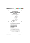
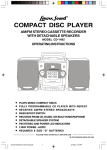
MODEL HT-377
2.1 CHANNEL HOME THEATER SYSTEM
•
•
•
•
•
•
Compatible with MP3 & DVD Players, Computers and
Game Consoles
Dual Stereo Inputs for Easy Connections - Includes All
Cables
Active Subwoofer for Deep Bass
Tower Speakers are Wall Mountable with Removable
Pedestals (bases)
Remote Control and Batteries Included
Operates on 120V AC Power
PLEASE READ CAREFULLY BEFORE USE
IB-HT377-WM-E-050405
IB-HT377-WM-E-050405.pmd
1
6/2/2005, 2:15 PM
SAFETY INSTRUCTIONS
WARNING
TO PREVENT FIRE OR SHOCK HAZARD, DO NOT USE THE PLUG WITH AN EXTENSION
CO RD, RECEPTACLE O R O THER O UTLET UNLESS THE BLADES CAN BE FULLY
INSERTED TO PREVENT BLADE EXPOSURE. TO PREVENT FIRE OR SHOCK HAZARD,
DO NOT EXPOSE THIS APPLIANCE TO RAIN OR MOISTURE. TO PREVENT ELECTRICAL
SHOCK, MATCH WIDE BLADE PLUG TO WIDE SLOT, FULLY INSERT.
CAUTION
RISK OF ELECTRIC SHOCK
DO NOT OPEN
The lightning flash with arrowhead
s ymbol, w it hin an equilateral
triangle, is intended to alert the user
to the presence of uninsulated
“dangerous voltage” within the
product’s enclosure that may be of
sufficient magnitude to constitute a
risk of electric shock to persons.
WAR N I N G : T O R ED U C E T H E
R I SK O F ELEC T R I C SH O C K,
DO NOT REMOVE COVER (OR
BACK). NO USER SERVICEABLE
PART S
I N SID E.
R EF ER
SER VI C I N G TO Q U ALI F I ED
SERVICE PERSONNEL.
The exclamation point within an
equilateral triangle is intended to
alert the user to the presence of
impor t ant oper at ing and
maint enanc e
( s er v ic ing)
instr uctions in the liter ature
accompanying the appliance.
See bottom of the set
IMPORTANT SAFETY INSTRUCTIONS
1.
2.
3.
4.
5.
6.
7.
8.
Read these instructions.
Keep these instructions.
Heed all warnings.
Follow all instructions.
Do not use this apparatus near water.
Clean only with dry cloth.
Do not block any ventilation openings, install in accordance with the manufacturer’s instructions.
Do not install near any heat sources such as radiators, heat registers, stoves, or other apparatus
(including amplifiers) that produce heat.
9. Do not defeat the safety purpose of the polarized or grounding-type plug. A polarized plug has
two blades with one wider than the other. A grounding type plug has two blades and a third
grounding prong. The wide blade or the third prong are provided for your safety. If the provided
plug does not fit into your outlet, consult an electrician for replacement of the obsolete outlet.
10 . Protect the power cord from being walked on or pinched particularly at plugs, convenience
receptacles, and the point where they exit from the apparatus.
11. Only use attachments/accessories specified by the manufacturer.
12 . Unplug this apparatus during lightning storms or when unused for long periods of time.
13 . Refer all servicing to qualified service personnel. Servicing is required when the apparatus has
been damaged in any way, such as power-supply cord or plug is damaged, liquid has been
spilled or objects have fallen into the apparatus, the apparatus has been exposed to rain or
moisture, does not operate normally or has been dropped.
14 . Use only with the cart, stand, tripod, bracket, or table specified by the manufacturer, or sold
with the apparatus. When a cart is used, use caution when moving the cart/apparatus combination
to avoid injury from tip-over.
15 . This appliance shall not be exposed to dripping or splashing water and that no object filled with
liquid such as vases shall be placed on the apparatus.
1
IB-HT377-WM-E-050405.pmd
2
IB-HT377-WM-E-050405
6/2/2005, 2:15 PM
SAFETY INSTRUCTIONS
FCC NOTE
This equipment has been tested and found to comply with the limits for a Class B digital
device, pursuant to Part 15 of the FCC rules. These limits are designed to provide reasonable
protection against harmful interference in a residential installation. This equipment generates,
uses and can radiate radio frequency energy and, if not installed and used in accordance
with the instructions, may cause harmful interference to radio communications. However,
there is no guarantee that interference will not occur in a particular installation. If this
equipment does cause harmful interference to radio or television reception, which can be
determined by turning the equipment off and on, the user is encouraged to try to correct
the interference by one or more of the following measures.
- Reorient or relocate the receiving antenna.
- Increase the separation between the equipment and receiver.
- Connect this equipment into an outlet on a circuit different from that to which the receiver
is connected.
- Consult the dealer or an experienced radio/TV technician for help.
CAUTION
FCC Regulations state that unauthorized changes or modifications to this equipment may
void the user’s authority to operate it.
PRECAUTIONS
ON SAFETY
Should any solid object or liquid fall into the Home Theater System, unplug the player,
and have it checked by qualified personnel before operating it any further.
ON PLACEMENT OF YOUR HOME THEATER SYSTEM
•
Do not leave the Home Theater in a location near a heat source, or in a place subject to
direc t s unlight, exc ess iv ely dusty ro oms or r ooms wit h v ery high hum idit y.
•
•
Do not place the Home Theater system on an inclined or unstable place.
Do not place anything within 1 inch of the sides or 2 inches from the back of the
cabinet. The heat sink fins must not be covered for the set to operate properly and
prolong the life of its components.
Please read important information displayed on the rating plate located on the bottom enclosure
before connecting to AC Mains or any operation.
2
IB-HT377-WM-E-050405.pmd
3
IB-HT377-WM-E-050405
6/2/2005, 2:15 PM
INTRODUCTION
Thank you for purchasing this 2.1 channel Home System. This deluxe audio theater system
turns your home into a virtual theater.
This system was designed to provide you with many years of reliable operation with a minimum
of care and maintenance. Every component in your system was perfect when it left our
factory. If you experience any problem with the set-up or operation of this system, please
review the Trouble Shooting Guide at the end of this manual before you contact the Customer
Service Department at 1-800-315-5885.
Basic Features & Benefits of this Home Theater System:
1.
2.
3.
4.
5.
6.
7.
Includes audio inputs for DVD, CD player, VCR, computer, MP3, GAME/CAMERA etc.
Customizable speaker level controls with indicators.
Powerful subwoofer provides real BOOM in your bass.
Deluxe easy-to-use remote control with batteries included.
LED indicators for DVD, MP3 functions.
Designed for easy, mistake-proof color-coded speaker setup.
Compatible with computer sound systems - audio cable is included.
THIS SYSTEM CONTAINS
1 Main Set (Subwoofer)
2 “AAA” batteries
2 Speakers
1 Remote Control
1 Set of Audio cable with 3.5mm
plug for Computer or MP3
Connection (or any other
Source with 3.5mm Jack)
3
IB-HT377-WM-E-050405.pmd
4
2 Speaker’s pedestals
1 Set of Audio cable
for DVD or AUX IN
(Red & White)
1 Spare Fuse
IB-HT377-WM-E-050405
6/2/2005, 2:15 PM
TABLE OF CONTENTS
• Getting Started
Safety Instructions--------------------------------------------------------------------------------------------1,2
Introduction-----------------------------------------------------------------------------------------------------3
Location of Controls------------------------------------------------------------------------------------------5,6
Remote Control Operation----------------------------------------------------------------------------------6,7
Positioning Information --------------------------------------------------------------------------------------7
• Connections
Speaker System Connections------------------------------------------------------------------------------8,9
TV Connections ----------------------------------------------------------------------------------------------10
TV + DVD Connections ------------------------------------------------------------------------------------11
TV + VCR Connections ------------------------------------------------------------------------------------12
TV + TV Game or Video Camera Connections ----------------------------------------------------------13
MP3/AUX Connections -------------------------------------------------------------------------------------14
• Amplifier in Main set---------------------------------------------------------------------------15,16
• Trouble Shooting -------------------------------------------------------------------------------16,17
• Specifications
--------------------------------------------------------------------------------------18
4
IB-HT377-WM-E-050405.pmd
5
IB-HT377-WM-E-050405
6/2/2005, 2:15 PM
LOCATION OF CONTROLS
1. REMOTE SENSOR - Receives the signal from
the REMOTE CONTROL (aim the R E M O T E
control towards this sensor).
2. ON/STANDBY button - Press to switch the
set to on or standby mode.
3. ON/STANDBY indicator - This indicator has
2 modes: flashing and steadily on (slow flashing
indicates the set is in standby, steadily on indicates
the set is on). When the set is turned to ON,
pressing the ON/STANDBY button on the main
set or on the REMOTE CONTROL will turn
the set to the standby mode, the indicator will
become slow flashing.
NOTE: The power switch on the back of the
main set must be ON.
4. VOLUME + button - Increases the volume.
5. VOLUME - button - Decreases the volume.
6. SOURCE button - Press to select the sound
input source you want: DVD or MP3/AUX.
7. DVD indicator - For DVD sound use, press the
SOURCE button on the main set or on the remote
control till this lights.
8. MP3 indicator - For MP3, PC or other component’s
output sound use, press the SOURCE button on
the main set or on the remote control till this lights.
FRONT PANEL
1
ON
STAN DBY
2
3
4
VOL+
VOL
5
SOURCE
6
7
8
DVD
MP3
BACK OF MAIN SET
(SUBWOOFER)
9
9
10
11
12
11
12
13
14
15
9. DVD AUDIO INPUT jacks - Connect to the
audio output of a DVD player or other component
with AUDIO output jacks to have 2.1 channel
sound.
10. MP3/AUX INPUT jack - Connect to the audio
output of an MP3 or PC or tape deck or other
component using a 3.5 mm audio output plug.
11. LEFT SPEAKER jacks - Connect one of the
SPEAKERS to the grey and black terminals.
12. RIGHT SPEAKER jacks - Connect one of the
SPEAKERS to the grey and black terminals.
13. FUSE HOLDER with screw cover.
14. AC LINE CORD - Connect to a 120V/60Hz
AC standard wall outlet.
15. POWER switch - Press to power the set on or off.
NOTE: This switch must be ON in order to be
able to use the ON/STANDBY button on the
main set or on the REMOTE CONTROL.
5
IB-HT377-WM-E-050405.pmd
6
IB-HT377-WM-E-050405
6/2/2005, 2:15 PM
LOCATION OF CONTROLS
REMOTE CONTROL
1
1. IR DIODE - Sends the signal to the set. Do not
block or cover this.
ON/STANDBY
2
2. ON/STANDBY button - Switches the player from
MUTE
S OUR CE
3
4
5
6
STANDBY to ON or ON to STANDBY.
3. MUTE button - Instantly turns off the sound. Press
again to restore the sound.
4. SOURCE button - Press to select the sound input
source you want: DVD or MP3.
5. VOLUME
button - Press to decrease the volume.
6. VOLUME
button - Press to increase the volume.
REMOTE CONTROL OPERATION
Battery Installation
Remove the BATTERY COMPARTMENT DOOR of the REMOTE CONTROL and insert 2 size
“AAA” alkaline batteries (included) according to the + and - markings inside the BATTERY
COMPARTMENT of the REMOTE CONTROL unit, replace the door.
Tips on Battery Use
Gently push here and slide to open the BATTERY
DOOR.
•
•
Insert 2 size “AAA” batteries as shown (included).
•
Remember, the spring touches the NEGATIVE (-)
side of each battery.
•
•
Replace the door.
6
IB-HT377-WM-E-050405.pmd
7
Revers ing polarities will damage the
batteries and possibly your REMOTE.
Be sure to follow polarity ( + and -) as
indicated.
Do not mix different ty pes batteries
together (Alkaline, Carbon-Zinc, NickelCadmium etc.), or old batteries with new
ones.
When not in use for an extended period of
time (over 60 days) remove the batteries
to prev ent pos s ible ac id leakage or
corrosion resulting in damage to your
remote.
When the batteries hav e bec ome
discharged, they must be disposed of in a
s afe manner that complies with all
applicable laws.
Installation of batteries should only be
done by an adult (for safety).
IB-HT377-WM-E-050405
6/2/2005, 2:15 PM
REMOTE CONTROL OPERATION
Remote Control Operation Range
Point the REMOTE CONTROL unit from less than 20 feet from the remote control sensor and
within about 600 of the front of the HOME THEATER SYSTEM (not your TV set or DVD player).
Point the REMOTE CONTROL in the
Right Direction
REMOT E SENSOR RANGE
When you want the remote to operate the
HOME THEATER SYSTEM, point the remote
at the HOME THEATER, not the TV set or
DVD player. The Remote has to be pointed in
the correct direction and toward the correct
component (HOME THEATER) in order for
the remote control’s signal to communicate
wit h th e re mote s en s or on t he H O ME
THEATER. Make sure there is a clear path
between the remote control and the HOME
THEATER so the signal is not blocked.
30
30
O
T i p s o n REM O T E CO NT RO L
Operation
o
•
Distance within 20 feet
•
•
•
Remember to point the REMOTE CONTROL
in the direction of the HOME THEATER, not
the TV set or DVD player.
•
Th e op erat ing dis tanc e ma y v a ry
according to the brightness of the room.
Do not point bright lights at the remote
control sensor (like laser pointers).
Do not place objects between the remote
control unit and the remote control sensor.
Do not us e thi s re mote c on trol whi le
simultaneously using the remote control
unit of any other equipment at the same
time, the signals may mix.
Sometimes your TV’s remote may cause
an LED to flash, you can ignore this.
POSITIONING INFORMATION
Subwoofer Position
The subwoofer will provide the most dramatic bass effects (low frequency sounds like explosions
and thunder) when it is placed on the floor. Do not place the subwoofer on a stand or table. The
subwoofer should be placed in the front of the room so that it is facing towards your listening
position. It can be placed on either side of the TV or even in the corner of the room, as far away
as the cable will allow. The bass sounds from the subwoofer are non-directional. You will not
really be able to tell where the bass is coming from.
Speaker’s pedestals Installation
In order to get better sound, We provide 2
pedestals for the speakers, please install them
as the right illustration.
7
IB-HT377-WM-E-050405.pmd
8
IB-HT377-WM-E-050405
6/2/2005, 2:15 PM
SPEAKER SYSTEM CONNECTIONS
Speaker System Connections
Connect the supplied speaker system by matching the colors of the terminals to those of
the cords.
IMPORTANT: Before making connections, make sure the power is off.
QUICK SETUP DIAGRAM
Video cable not included
IMPORTA NT NOTE
FOR DVD USE: This
Home Theater system
only improve the sound
of your DVD player; for
you r D VD ’s vi de o
output, connect the
video output jack to your
TV’s video input jack.
RED
WHITE
WHITE
OR
OR
RED
OR
WHITE
WHITE
RED
RED
RED
WHITE
GREEN
SPEAKERS
Remember to flip the main
switch to the ON position.
NOTE: In order to have TV sound come through your home theater system, your TV must
have AUDIO OUTPUT jacks. These jacks will always be in the rear of the TV (and not in the
front). If your TV does not have these output jacks, you have to use a cable box or a satellite
receiver to get the audio.
8
IB-HT377-WM-E-050405.pmd
9
IB-HT377-WM-E-050405
6/2/2005, 2:15 PM
SPEAKER SYSTEM CONNECTIONS
Tips for connecting the speaker wires
Unwind and stretch out the speaker wires
attached with each speakers, then push the
set terminal tab on the back of the main set to
insert each wire. Make sure the wire is fully
inserted, but the insulation is not covering the
inserted part of the speaker wires.
To avoid short-circuiting the speakers
•
Make sure the stripped end of each speaker
wire does not touch another set terminal or
the stripped end of another speaker wire.
Examples of poor connection of the
speaker wires
SET TERMINAL
LOOSE STRANDS TOUCHING
(This will short out the sound)
PUSH THE TAB OF TERMINAL.
•
Stripped speaker wire is touching another
set terminal. Make sure not even 1 strand
of wire touches the other wire!
WIRES SHORTED TO EACH OTHER
(This will short out the sound)
STICK THE EXPOSED PART OF THE WIRE INTO
THE HOLE OF THE TERMINAL.
•
PUSH THE TERMINAL TO LOCK THE WIRE INSIDE
THE TERMINAL.
MAKE SURE POWER IS OFF WHEN
DONG THE ABOVE
NOTE:
Be sure to match the speaker wire to the
appropriate terminal on the back of the main
set: grey to grey, and black to black. If the
wires are reversed, the sound will be distorted
and will lack some tones. Follow the color
codes of each terminals.
MAKE SURE ABOVE DOES NOT HAPPEN
NOTE: If longer wires are needed, you may buy
any good quality speaker wire and splice the wires
yourself. Please make sure the wires are not
shorting to each other and observe the correct
color polarity. Many speaker wires have a dotted
line or solid line or raised rib on one side to identify
each side. Also make sure you use electrical tape
to cover your splices.
9
IB-HT377-WM-E-050405.pmd
10
Stripped wires are touching each other due
to excessive removal of insulation. Do not
allow the above to happen on your set.
IB-HT377-WM-E-050405
6/2/2005, 2:15 PM
TV CONNECTIONS
Home Theater System + TV (if your TV has Audio Output jacks)
LEFT
MP3
AUX
INPUT
DVD
INPUT
RIGHT
AUDIO
NOTE: In order to have TV sound come through your home
theater system, your TV must have AUDIO OUTPUT jacks.
These jacks will always be in the rear of the TV (and not in
the front). If your TV does not have these output jacks, you
have to use a cable box or a satellite receiver to get the audio.
If you have a cable box or satellite receiver, you can connect the
receiver AUDIO OUTPUT directly to your DVD INPUT jack on the
back of the HOME THEATER SYSTEM.
CONNECT THE SPEAKERS AS SHOWN ON PAGE 8 (OR THE QUICK SETUP DIAGRAM SHEET).
1.
Insert the stereo audio cables (included) into the DVD INPUT LEFT and RIGHT jacks on the
back of your HOME THEATER SYSTEM, and into the corresponding AUDIO output jacks
on your TV, this will allow your TV’s s ound to play through y our HOME THEATER
SYSTEM. You will hear sound from both the TV and your HOME THEATER, this is normal.
NOTE: On some TVs, you may have to activate the audio out jacks of your TV. See your
TV’s booklet.
2.
Insert the AC power cord into an AC outlet.
3.
Make sure the POWER switch on the back of the main set is at “ON” position. Next press
the ON/STANDBY button on the front of the main set or on the REMOTE CONTROL to
switch the set on (or standby).
4.
Press the SOURCE button till the DVD indicator lights.
NOTE: The factory’s default input source is DVD. When the set is turned to ON, the DVD
indicator will be on, press the SOURCE button to turn on the MP3 indicator if you use
the 3.5 mm plug audio cable.
5.
Go to Page 15 for other detailed instructions.
NOTE: Your cable or antenna connection to your TV is not touched with this connection.
Leave your antenna cable to your TV as you normally would. No changes will be made
to your current antenna connections.
10
IB-HT377-WM-E-050405.pmd
11
IB-HT377-WM-E-050405
6/2/2005, 2:15 PM
TV + DVD CONNECTIONS
Home Theater System + TV + DVD Player
LEFT
MP3
AUX
INPUT
DVD
INPUT
RIGHT
AUDIO
NO TE: Som e ne wer T V s et s ha v e s e v era l VID EO
INPUT jacks. You may use one of these for your DVD
player and the others for connecting to the VIDEO OUT
jacks of the component. If your set is older and only has
a single VIDEO INPUT jack, you may buy a switch box
to change the video of DVD and Game.
NOTE: On some TVs, this
jack is in the front.
CONNECT THE SPEAKERS AS SHOWN ON PAGE 8 (OR THE QUICK SETUP DIAGRAM SHEET).
1.
Insert the stereo audio cables (included) into the DVD INPUT LEFT and RIGHT jacks on the
back of your HOME THEATER SYSTEM, and into the corresponding AUDIO output jacks
on your DVD player, this will allow your DVD’s sound to play through your HOME THEATER
SYSTEM.
2.
Insert the video cable into the VIDEO OUT jack on the back of your DVD player and into
the VIDEO IN jack on the back of your TV set. This is especially convenient if your TV has
several inputs.
3.
Insert the AC power cord into an AC outlet.
4.
Make sure the POWER switch on the back of the main set is at “ON” position. Next press
the ON/STANDBY button on the front of the main set or on the REMOTE CONTROL to
switch the set on (or standby).
5.
Press the SOURCE button till the DVD indicator lights.
NOTE: The factory’s default input source is DVD. When the set is turned to ON, the DVD
indicator will be on, press the SOURCE button to turn on the MP3 indicator if you use
the 3.5 mm plug audio cable.
6.
Go to Page 15 for other detailed instructions.
NOTE: Your cable or antenna connection to your TV is not touched with this connection.
Leave your antenna cable to your TV as you normally would. No changes will be made
to your current antenna connections.
11
IB-HT377-WM-E-050405.pmd
12
IB-HT377-WM-E-050405
6/2/2005, 2:15 PM
TV + VCR CONNECTIONS
Home Theater System + TV + VCR
RED
WHITE
RED
WHITE
LEFT
MP3
AUX
INPUT
DVD
INPUT
RIGHT
This does not change from
your current connection.
AUDIO
ANTENNA CABLE OR
OFF-AIR SIGNAL
NOTE: On some TVs, this
jack is in the front.
CONNECT THE SPEAKERS AS SHOWN ON PAGE 8 (OR THE QUICK SETUP DIAGRAM SHEET).
1.
Insert the stereo audio cables (included) into the DVD INPUT LEFT and RIGHT jacks on the
back of your HOME THEATER SYSTEM, and into the corresponding AUDIO output jacks
on your VCR, this will allow your VCR’s sound to play through your HOME THEATER
SYSTEM.
2.
Connections of your other antenna cables are not changed when you add your HOME
THEATER SYSTEM. You will hear sound from both the TV and your HOME THEATER,
this is normal.
3.
Insert the AC power cord into an AC outlet.
4.
Make sure the POWER switch on the back of the main set is at “ON” position. Next press
the ON/STANDBY button on the front of the main set or on the REMOTE CONTROL to
switch the set on (or standby).
5.
Press the SOURCE button till the DVD indicator lights.
NOTE: The factory’s default input source is DVD. When the set is turned to ON, the DVD
indicator will be on, press the SOURCE button to turn on the MP3 indicator if you use
the 3.5 mm plug audio cable.
6.
Go to Page 15 for other detailed instructions.
12
IB-HT377-WM-E-050405.pmd
13
IB-HT377-WM-E-050405
6/2/2005, 2:15 PM
TV + TV GAME OR VIDEO CAMERA CONNECTIONS
Home Theater System + TV + TV Game or Video Camera
TV GAME
RED
VIDEO CAMERA
WHITE
RED
VIDEO OUTPUT
WHITE
LEFT
INPUT
DVD
INPUT
RIGHT
MP3
AUX
AUDIO
NOTE: Your TV Game or Video Camera
may have a special cable (with a triple
3.5m m plug on one side) for
connections. This diagram is only for
illustrations.
NOTE: If your TV set has several VIDEO
INPUT jacks, you may connect your TV Game
or Video Camera cable to one of your TV’s
VIDEO INPUT jacks directly.
NOTE: On some TVs,
this ja ck is in the front.
CONNECT THE SPEAKERS AS SHOWN ON PAGE 8 (OR THE QUICK SETUP DIAGRAM SHEET).
1.
Insert the stereo audio cables (included) into the DVD INPUT LEFT and RIGHT jacks on the
back of your HOME THEATER SYSTEM, and into the corresponding AUDIO output jacks
on your TV Game or Video Camera, this will allow your TV Game or Video Camera’s
sound to play through your HOME THEATER SYSTEM.
2.
Insert the video cable into the VIDEO OUT jack of your TV Game or Video Camera player
and into the VIDEO IN jack on the back of your TV set. This is especially convenient if
your TV has several inputs.
3.
Insert the AC power cord into an AC outlet.
4.
Make sure the POWER switch on the back of the main set is at “ON” position. Next press
the ON/STANDBY button on the front of the main set or on the REMOTE CONTROL to
switch the set on (or standby).
5.
Press the SOURCE button till the DVD indicator lights.
NOTE: The factory’s default input source is DVD. When the set is turned to ON, the DVD
indicator will be on, press the SOURCE button to turn on the MP3 indicator if you use
the 3.5 mm plug audio cable.
6.
Go to Page 15 for other detailed instructions.
13
IB-HT377-WM-E-050405.pmd
14
IB-HT377-WM-E-050405
6/2/2005, 2:15 PM
MP3/AUX CONNECTIONS
LEFT
MP3
AUX
INPUT
DVD
INPUT
RIGHT
AUDIO
YOUR PC, CD, MP3 PLAYER OR
ANY RADIO OR OTHER SOURCE
WITH 3.5MM STEREO JACK
CONNECT THE SPEAKERS AS SHOWN ON PAGE 8 (OR THE QUICK SETUP DIAGRAM SHEET).
1.
Insert the green 3.5 mm audio cable (included) into the MP3/AUX INPUT jack on the back
of your HOME THEATER SYSTEM, and into the corresponding AUDIO output jack on
your MP3, PC, CD player, or other device, this will enable you to hear your components
system through your HOME THEATER SYSTEM.
2.
Insert the AC power cord into an AC outlet.
3.
Make sure the POWER switch on the back of the main set is at “ON” position. Next press
the ON/STANDBY button on the front of the main set or on the REMOTE CONTROL to
switch the set on (or standby).
4.
Press the SOURCE button till the MP3 indicator lights.
NOTE: The factory’s default input source is DVD. When the set is turned to ON, the DVD
indicator will be on, press the SOURCE button to turn on the MP3 indicator.
5.
Go to Page 15 for other detailed instructions.
14
IB-HT377-WM-E-050405.pmd
15
IB-HT377-WM-E-050405
6/2/2005, 2:15 PM
AMPLIFIER IN MAIN SET
REMOTE CONTROL
CONTROL PANEL
(ON THE FRONT OF THE SUBWOOFER)
ON/S TA NDB Y
ON/STANDBY
button
MU TE SOUR CE
MUTE
button
SOURCE
button
VOLUME button
VOLUME +
button
ON/STANDBY
button
VOLUME +
button
SOURCE
button
MP3
indicator
ON
STAN DB Y
ON/STANDBY
indicator
VOL
VOLUME button
VOL
SOURC E
DVD
indicator
D VD
MP3
General
1 Make sure the POWER switch on the back of the main set is at “ON” position. Next press the
ON/STANDBY button on the front of the main set or on the REMOTE CONTROL to turn the set
on (or standby).
NO TE: The STANDBY indicator has 2 modes: flashing and steadily on (slow flashing
indicates the set is in standby mode, steadily on indicates the set is on). When the set
is on, pressing the ON/STANDBY button on the main set or on the REMOTE
CONTROL will turn the set to the standby mode, the indicator will become slow
flashing.
2 Press the SOURCE button on the front panel of the main set or on the REMOTE CONTROL
to select one of the audio input sources, the corresponding indicator will light, the factory’s
default input source is DVD, when the set is turned on, the DVD indicator will be on.
3 For
volume adjustments, press the volume control buttons on the Remote control, the ON/
STANDBY indicator will flash to show you that the remote signal is received.
NO TE: Every time you turn the set on, the VOLUME will go back to the factory’s default
setting; and whenever you press the SOURCE button on the main unit or on the REMOTE,
the VOLUME will go back to the factory’s default setting. This avoids sudden very loud
sounds from startling you.
4 To momentarily
shut off the sound, press the MUTE button. The source indicator (DVD or
MP3) will flash. Press the MUTE button again or press the VOLUME buttons to restore the sound.
NOTE: Flip the POWER switch on the back of the main set to “OFF” if the set will not be used
for a long period of time (several days or more).
15
IB-HT377-WM-E-050405.pmd
16
IB-HT377-WM-E-050405
6/2/2005, 2:15 PM
AMPLIFIER IN MAIN SET
About fuse replacement
NOTE: Before attempting to change the fuse, the system must be unplugged from the wall outlet.
In the unusual event that nothing lights up and no sound, your fuse may have blown. To check for
a blown fuse, follow the steps below.
GOOD FUSE
1. O p en
t he f us e c ov e r ( on t he b ac k of
th e ma in s et) by u s in g a flat bla de
screwdriver to unscrew the fuse cover cap.
2. Examine the fuse. If a wire shows,
the fuse is good.
3. If
the wire is brok en in the middle,
replace with a 500 mA 250V “T” type
glass fuse.
“T” means time delay or s low blow
fuse.
BLOWN FUSE
TROUBLE SHOOTING
Symptom
Remedy
No power
1.Is the power cord firmly plugged into the power outlet? Insert
the AC power plug securely into the power outlet. Make sure
your outlet has power, you can check this by plugging a lamp
into the outlet to see if it works.
2.Is the main power switched to off? Flip it to ON.
3.One of the safety mechanisms may be operating. In this event,
unplug the player from the power outlet briefly and then plug
it in again to reset the set.
No power
Your set’s fuse may have blown.
Unscrew the fuse cover & check the fuse.
Replace only with same 500 mA slow blow 250V “T” type glass
fuse.
Your DVD player has no
picture
Make sure your DVD’s video cable is plugged into your TV set.
This Home Theater only improves the sound of your DVD player,
it does not affect the video at all. Also select the correct VIDEO
INPUT on your TV.
16
IB-HT377-WM-E-050405.pmd
17
IB-HT377-WM-E-050405
6/2/2005, 2:15 PM
TROUBLE SHOOTING
Symptom
• No
sound or only a very
low-level sound is heard.
• Distorted sound.
The REMO TE CO NTRO L
unit does not work.
No buttons operate (on the
main set and / or the REMOTE
CONTROL unit).
Remedy
1.Check that the s peakers and components are connected
securely and correctly, make sure the stripped end of each
speaker wires does not touch each other to avoid short-circuit
of the speaker wires (see Page 8, 9).
2.Make sure your source (DVD or other) is plugged in and
operating. Also check that component’s booklet, maybe you
need adjust that component.
3.Check and make sure your DVD’s sound output is set to
analog. For some DVDs, if the sound output is not set to
analog, the audio cables may not be active and there will be
no sound output.
4.Make sure that you have selected the correct source on the
system (DVD or MP3).
5.Adjust the set’s volume settings on the front of the HO ME
THEATER or on the remote, also adjust the volume of the
input source.
6.Ensure the MUTE button is not pressed on the HOME THEATER
remote (If yes, press the MUTE button again).
7.The audio or speaker connecting wires are damaged. Replace
them with new ones.
1.Check if the batteries are installed with the correct polarities
( + and - ).
2.If the batteries are weak or dead, replace them with new
ones (size “AAA”).
3.Point the remote control unit at a distance of less than 20 feet
from the main unit of the HOME THEATER system.
4.Remove any obstacles between the remote control unit and
remote control sensor.
5.If the battery terminals are dirty or corroded, clean them with
sandpaper.
Press the POWER button on the back of the MAIN SET to turn
the set ON. Then press the ON/STANDBY button on the main
set or on the REMOTE. The HOME THEATER may not be
operating properly due to lightning, static electricity, or some
other external factors. Reset the player by disconnecting the
power plug and then re-connecting it before calling customer
service. Also check the Fuse. See page 16.
The left and right sounds are
unbalanced or reversed.
Check that the speakers and components are connected correctly and securely.
Loud hum or noise is heard.
1.Check that the s peakers and components are connected
securely.
2.Insert all wires firmly, follow the setup pages starting on Page 8.
Loud hum usually means a plug is not fully seated into the jack.
The s y s tem does not
operate properly.
Double check if input & output jacks were inserted properly.
Also ask a friend to help you before calling customer service.
17
IB-HT377-WM-E-050405.pmd
18
IB-HT377-WM-E-050405
6/2/2005, 2:15 PM
SPECIFICATIONS
General
Power requirements ------------------- AC 120V, 60Hz
Power consumption -------------------- 55 Watts
Main set Dimensions ------------------ 55/8 X 101/4 X 97/8 inches / 143 X 260 X 251 mm
Weight -------------------------- 2.86 kg
Speaker Dimensions ------------------ 31/8 X 33/8 X 85/8 inches / 79 X 86 X219 mm
Weight -------------------------- 0.29 kg
Audio Power Output
Total output power: 50 Watts at Maximum
Distortion
0.06% @ reference output
Remote Operating Range
Within 20 feet between the main set and the remote.
Replacement Fuse
Time delay 500 mA T type (slow blow) glass fuse 250V.
LENOXX reserves the right to make design and specification changes for product improvement.
PROTECT YOUR FINE FURNITURE!
WE RECOMMEND A CLOTH OR OTHER PROTECTIVE MATERIAL BE PLACED UNDER
THE SET OR SPEAKERS WHEN PLACING IT O N A SURFACE WITH A NATURAL OR
LACQUER FINISH.
For customer service of this Durabrand product Dial: 1-800-315-5885
(MONDAY-THURSDAY 8:00 AM - 5:00 PM, FRIDAY 8:00 AM - 1:00 PM EST)
© 2005 LENOXX ELECTRONICS CORP.
2 GERMAK DRIVE
CARTERET, N.J. 07008
http://www.lenoxx.com
MADE & PRINTED IN CHINA
18
IB-HT377-WM-E-050405.pmd
19
IB-HT377-WM-E-050405
6/2/2005, 2:15 PM