1
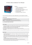
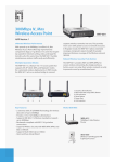
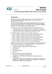
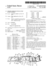
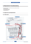
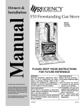
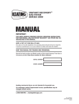
HEARTH PRODUCTS
KITS AND ACCESSORIES
750,216M
REV. N/C 03/2006
BLOWER KIT
LBLK-100
INSTALLATION INSTRUCTIONS FOR BLOWER KIT
LBLK-100 (CATALOG NO. H4678) FOR USE WITH ELDV SERIES FIREPLACES
Step 6. Remove the logs from the fireplace (see Figure 1 ). Handle logs
carefully to prevent breakage.
GENERAL INFORMATION
This blower kit may be used with ELDV series fireplaces. The LBLK100 blower kit is used with a field supplied ON/OFF power switch. The
blower is installed beneath the firebox. Room air is drawn in through
the bottom area of the fireplace, heated as it passes across the
firebox, and discharged through the upper open area at the top of the
fireplace. The LBLK-100 blower kit contains one blower, one power
cord and these instructions.
Step 7. Remove the grate asembly, burner baffle, burner asembly
(Figure 2 ) and the blower cover panel (Figure 3 ).
Step 8. Connect the provided power cord to the terminals on the blower.
Blower Cover Panel
INSTALLATION INSTRUCTIONS
Burner Assembly
Step 1. Turn off the fireplace and allow it to cool before proceeding.
Step 2. If the appliance is connected to 120 volt power, disconnect
the power.
Step 3. Shut off the gas supply to the fireplace.
Step 4. Remove the bottom panel of the fireplace by pulling it forward.
(see Figure 1 ).
Step 5. Remove the door assembly by opening the two latches (located
under the door assembly) securing the glass door (see Figure 1 ).
Grate Assembly
Logs
Door Asembly
Burner Baffle
Figure 2
Blower Cover Panel
Bottom Panel
Figure 1
Figure 3
NOTE: DIAGRAMS & ILLUSTRATIONS NOT TO SCALE.
1
Step 9. - Installing The LBLK-100 Blower
9A. First, tilt the left side of the blower into the cutout (see Figure 4 ).
Cabinet Bottom
Left Side Of Blower Assembly Tilted Into Access Cutout
Figure 6
Blower Access Cutout
Figure 4
Step 9B. Next, rest the blower on the cabinet bottom (see Figure 5 ).
Blower Access Cutout
Cabinet Bottom
Blower Assembly Base
Figure 7
Step 9E. Place the blower assembly in its final position at the back of the
cabinet bottom, resting on the blower mounting tabs (see Figure 8 ).
Bend the mounting tabs over the blower base to secure.
Blower Assembly
LBLK-100 Blower Resting On Cabinet Bottom
Figure 5
Step 9C. Now gently slide the blower assembly towards the back of the
fireplace (see Figure 6 ).
Step 9D. Rotate the blower assembly so the base rests on the cabinet
bottom (see Figure 7 ).
Blower Mounting Tab
Figure 8
2
NOTE: DIAGRAMS & ILLUSTRATIONS NOT TO SCALE.
Blower Base
WIRING DIAGRAM MILLIVOLT GAS VALVES
INTERMITTENT ELECTRONIC WIRING DIAGRAM
THERMOPILE
120 VAC
SPARK TO PILOT IGNITOR
BK W GR
APPLIANCE- MOUNTED
ON/OFF SWITCH
BK
TP
TH
IGNITOR MODULE
3V
R
GAS VALVE
BK
BK/W(1)
W
OPTIONAL BLOWER
SWITCH
BK/W(1)
GR
TP-TH
JUNCTION BOX
BLACK (IGNITOR)
WALL-MOUNTED ON/OFF SWITCH (OPTIONAL)
THERMOSTAT (OPTIONAL)
TRANSFORMER 3V
BLACK (SENSOR)
WALL MOUNTED CONFIGURATION FOR FAN SWITCH (OPTIONAL)
BLACK
FAN
(OPTIONAL)
BLACK
BK
ORANGE (THTP)
IN
LO
HI
GREEN (TH)
IN
RED
OUT
TH
120 V
AC
BLACK (TP)
TP
GR
BATTERY BACK-UP
TO WALL
SWITCH OR
THERMOSTAT
TH
TP
W
PILOT
R
VENT
BROWN
FAN
(OPTIONAL)
BROWN
JUNCTION BOX
Figure 9
Figure 10
Step 10. Install the field-provided ON/OFF switch in a convenient
location on a wall, near the fireplace.
Step 11. Route a 3-wire, 120Vac power line to the ON/OFF switch as
shown in Figure 9 (for Millivolt model) and Figure 10 (for Electronic
model).
IMPORTANT: Ground lead must be connected to the green screw
located on the junction box. Failure to do so will prevent the
appliance from operating. The appliance must be electrically
grounded in accordance with local codes or, in the absence of local
codes, the National Electrical Code, ANSI/NFPA 70-(latest edition).
(In Canada, the current CSA C22-1 Canadian Electrical Code.)
Then route the wires to the unit’s junction box. Remove the receptacle
box by squeezing the sides of the J-Box and slide the two tabs through
the cutout.
BLOWER ASSEMBLY
Step 12. Connect the supply wires to the receptacle as shown in
Figure 9 (for Millivolt) and Figure 10 (for Electronic). Reinstall the
receptacle box.
Step 13. Plug the blower cord into the receptacle (see Figure 11 ).
Step 14. Reinstall items from Steps 7, 6 and 5.
BLOWER MOUNTING TABS
Step 15. Restore the electrical power to the unit.
ELECTRICAL OUTLET
Step 16. Start the fireplace by following the procedures indicated in
the lighting instructions section of the Homeowners Care And Operations instructions manual, supplied with the fireplace.
Figure 11
Step 17. Check the start-up and shutdown, and the running operation
of the blower.
NOTE: DIAGRAMS & ILLUSTRATIONS NOT TO SCALE.
3
The manufacturer reserves the right to make changes at any time, without notice, in design,
materials, specifications, prices and also to discontinue colors, styles and products.
Consult your local distributor for fireplace code information.
Printed in U.S.A. © 2006 by Lennox Hearth Products
4
P/N 750,216M REV. N/C 03/2006
NOTE: DIAGRAMS & ILLUSTRATIONS NOT TO SCALE.
1110 West Taft Avenue - Orange, CA 92865