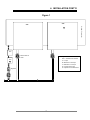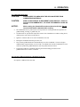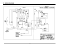
1
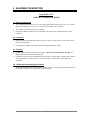
Installation Operation Maintenance Troubleshooting Model: AGC Add-on Clamshell® Hood Lang Manufacturing Company Part Number: 60801- 6500 Merrill Creek Parkway Phone: 425-349-2400 Fax: 425-349-2733 WWW.LANGWORLD.COM Everett, WA 98203 © Copyright 1998 THIS MANUAL MUST BE RETAINED FOR FUTURE REFERENCE. READ, UNDERSTAND AND FOLLOW THE INSTRUCTIONS AND WARNINGS CONTAINED IN THIS MANUAL. FOR YOUR SAFETY DO NOT STORE OR USE GASOLINE OR OTHER FLAMMABLE VAPORS AND LIQUIDS IN THE VICINITY OF THIS OR ANY OTHER APPLIANCE. POST IN A PROMINENT LOCATION INSTRUCTIONS TO BE FOLLOWED IN THE EVENT USER SMELLS GAS. THIS INFORMATION SHALL BE OBTAINED BY CONSULTING YOUR LOCAL GAS SUPPLIER. AS A MINIMUM, TURN OFF THE GAS AND CALL YOUR GAS COMPANY AND YOUR AUTHORIZED SERVICE AGENT. EVACUATE ALL PERSONNEL FROM THE AREA. WARNING: IMPROPER INSTALLATION, ADJUSTMENT, ALTERATION, SERVICE OR MAINTENANCE CAN CAUSE PROPERTY DAMAGE, INJURY OR DEATH. READ THE INSTALLATION, OPERATING AND MAINTENANCE INSTRUCTIONS THOROUGHLY BEFORE INSTALLING OR SERVICING THIS EQUIPMENT. Model #: Purchased From: Serial #: Location: Date Purchased: Date Installed: Purchase Order #: For Service, Call: 2 TABLE OF CONTENTS CHAPTER PAGE 1. READ FIRST ................................................................................................................. 4 2. EQUIPMENT DESCRIPTION........................................................................................ 6 3. UNPACKING ................................................................................................................. 7 4. INSTALLATION ............................................................................................................. 8 5. INITIAL START-UP ....................................................................................................... 10 6. OPERATION ................................................................................................................. 11 7. SEQUENCE OF OPERATION ..................................................................................... 12 8. CLEANING & MAINTENANCE PROCEDURES .......................................................... 13 9. TROUBLESHOOTING .................................................................................................. 14 10. PARTS LISTS................................................................................................................ 16 11. WIRING DIAGRAMS ..................................................................................................... 18 12. WARRANTY .................................................................................................................. 19 3 IMPORTANT READ FIRST IMPORTANT NOTICE: If the Clamshell® is to be attached to a griddle/ charbroiler in the field – it is recommended to complete the installation of mounting adapter before un-crating the Clamshell®. CAUTION: UNIT IS EXTREMELY HEAVY. FOR SAFE HANDLING, INSTALLER SHOULD OBTAIN HELP AS NEEDED, OR EMPLOY APPROPRIATE MATERIALS HANDLING EQUIPMENT (SUCH AS A FORKLIFT, DOLLY, OR PALLET JACK) TO REMOVE THE UNIT FROM THE SKID AND MOVE IT TO THE PLACE OF INSTALLATION. WARNING: INSTALLATION OF THE UNIT MUST BE DONE BY PERSONNEL QUALIFIED TO WORK WITH ELECTRICITY AND PLUMBING. IMPROPER INSTALLATION CAN CAUSE INJURY TO PERSONNEL AND/OR DAMAGE TO EQUIPMENT. UNIT MUST BE INSTALLED IN ACCORDANCE WITH ALL APPLICABLE CODES. CAUTION: SHIPPING STRAPS ARE UNDER TENSION AND CAN SNAP BACK WHEN CUT. DANGER: DO NOT REMOVE THE MOUNTING NUTS OFF OF THE MOUNTING PLATE STUDS WHILE THE UNIT IS IN THE LOWERED POSITION. THE STANCHION BACK IS UNDER TENSION AND CAN CAUSE BODILY INJURY. NOTICE: The data plate is located on the inside surface of the hood wrap. The Clamshell® voltage, wattage, serial number, clearance and gas specifications are on the data plate. This information should be carefully read and understood before proceeding with the installation. NOTICE: This unit is approved to be installed only on equipment which meets NSF standards, and for which the adapter kit is provided. WARNING: BEFORE LIGHTING, USE A SOAP AND WATER SOLUTION TO TEST ALL JOINTS FOR GAS LEAKS. NOTICE: The installation of any components such as a vent hood, grease extractors, fire extinguisher systems, must conform to their applicable National, State and locally recognized installation standards. WARNING: DURING INITIAL USE, OR USE AFTER SERVICE, IF THE PILOT DOES NOT IGNITE ON FIRST TRY THE MAIN GAS VALVE MUST BE TURNED OFF FOR AT LEAST FIVE MINUTES. CAUTION: ALWAYS KEEP THE AREA NEAR THE APPLIANCE FREE FROM COMBUSTIBLE MATERIALS. CAUTION: KEEP FLOOR IN FRONT OF EQUIPMENT CLEAN AND DRY. IF SPILLS OCCUR, CLEAN IMMEDIATELY, TO AVOID THE DANGER OF SLIPS OR FALLS. NOTICE: While cooking, the Clamshell® must be monitored at all times. Do not leave the Clamshell® unattended while cooking. NOTICE: Fan in Clamshell® runs continuously. For the safety of the unit, the fan must run continuously to provide cooling to the electrical components. Component cooling is required if the base unit is running. If power to the Clamshell® is turned off, gas to base will be turned off. If it is necessary to remove power from the Clamshell®, the base unit must be cooled below 200°F first. 4 IMPORTANT READ FIRST IMPORTANT WARNING: KEEP WATER AND SOLUTIONS OUT OF CONTROLS. NEVER SPRAY OR HOSE CONTROL CONSOLE, ELECTRICAL CONNECTIONS, ETC. CAUTION: MOST CLEANERS ARE HARMFUL TO THE SKIN, EYES, MUCOUS MEMBRANES AND CLOTHING. PRECAUTIONS SHOULD BE TAKEN TO WEAR RUBBER GLOVES, GOGGLES OR FACE SHIELD AND PROTECTIVE CLOTHING. CAREFULLY READ THE WARNING AND FOLLOW THE DIRECTIONS ON THE LABEL OF THE CLEANER TO BE USED. CAUTION: A COMMERCIAL LIQUID GRIDDLE CLEANER IS NOT RECOMMENDED FOR CLEANING THE GRIDDLE OR CHARBROILER UNDER THE CLAMSHELL® AS MOST CONTAIN POTASSIUM HYDROXIDE OR SODIUM HYDROXIDE WHICH IS HARMFUL TO THE CLAMSHELL® BURNER TILES. NOTICE: Do not spray any liquids on to the tiles, or wipe the tiles with any materials. Liquids and direct contact on the tiles can damage them. CAUTION: DO NOT USE YOUR HAND TO CHECK GRIDDLE/CHARBROILER TEMPERATURE. Service on this, or any other, LANG appliance must be performed by qualified personnel only. Consult your authorized service station directory or call the factory at 1-800-224-LANG (5264), or WWW.LANGWORLD.COM For the service station nearest you. NOTICE: DANGER: BOTH HIGH AND LOW VOLTAGES ARE PRESENT INSIDE THIS APPLIANCE WHEN THE UNIT IS PLUGGED/WIRED INTO A LIVE RECEPTACLE. BEFORE PERFORMING ANY WORK ON INTERNAL COMPONENTS, DISCONNECT THE APPLIANCE FROM THE ELECTRIC POWER SUPPLY. CAUTION: USE OF ANY REPLACEMENT PARTS OTHER THAN THOSE SUPPLIED BY LANG OR THEIR AUTHORIZED DISTRIBUTORS CAN CAUSE BODILY INJURY TO THE OPERATOR AND DAMAGE TO THE EQUIPMENT AND WILL VOID ALL WARRANTIES. CAUTION: BE SURE ALL OPERATORS READ, UNDERSTAND AND FOLLOW THE OPERATING INSTRUCTIONS, CAUTIONS AND SAFETY INSTRUCTIONS CONTAINED IN THIS MANUAL. 5 2. EQUIPMENT DESCRIPTION Lang Model: AGC ADD-ON CLAMSHELL® HOOD 2.1 Exterior Construction • The Clamshell® dimensions are 19 1/2” (49.53cm) High in the lowered position, 38 1/3” (97.36cm) High in the raised position, 36 3/4” (93.35cm) Deep, and width is 24” (60.96cm). • The stainless steel hood makes for easy cleaning. • Pivoting heat deflector redirects excess grill heat to either side of the equipment and away from employees. 2.2 Operation • By heating only when in the down position, you can conserve energy and save money with a cooler backroom environment. • Cook different products at the same time with no height adjustments needed. 2.3 Technical • Griddle operates on either Natural Gas or Propane. This must be specified when ordering. It is shipped with a Power Cord and Plug attached. • Clearances required from non-combustible surfaces: Back: 0 inches, Sides: maintain side clearance of base appliance or 3 inches which ever is greater, Bottom: 6 inches below the bottom of the stanchions. 2.4 Griddle Gas and Voltage Specifications The Lang Clamshell® can be connected to any 220 Volt source. The gas specifications are listed on the data label located on the inside surface of the hood wrap. 6 3. UNPACKING 3.1 Receiving the Clamshell® Upon receipt, check for freight damage, both visible and concealed. Visible damage should be noted on the freight bill at the time of delivery and signed by the carrier's agent. Concealed loss or damage means loss or damage which does not become apparent until the merchandise has been unpacked. If concealed loss or damage is discovered upon unpacking, make a written request for inspection by the carrier's agent within 15 days of delivery. All packing material should be kept for inspection. Do not return damaged merchandise to Lang Manufacturing Company. File your claim with the carrier. 3.2 Location Prior to un-crating, move the Clamshell® as near to its intended location as practical. The crating will help protect the unit from physical damage normally associated with moving it through hallways and doorways. NOTICE: If the Clamshell® is to be attached to a griddle/ charbroiler in the field – it is recommended to complete the installation of mounting adapter before un-crating the Clamshell®. 3.3 Un-crating the Add-on Clamshell® Hood If Clamshell® is received already attached to a Griddle/Charbroiler skip to section 3.4. The Clamshell® will arrive completely assembled inside a wood frame covered by a cardboard box and bolted to a skid. Remove the cardboard cover, unbolt Clamshell® from the support brackets. Discard the skid and brackets. Remove Clamshell® from skid and place in intended location. There are several parts that are not installed in the unit. Be careful not to misplace the following parts when un-crating the unit. Inner Component Cover Outer Component Cover Inner Flue Outer Flue Insulation Manual Shut-off Valve Two 3/8 X 16 Nuts Note: See Mounting Adapter kit for instructions on installing these parts. CAUTION: UNIT IS EXTREMELY HEAVY. FOR SAFE HANDLING, INSTALLER SHOULD OBTAIN HELP AS NEEDED, OR EMPLOY APPROPRIATE MATERIALS HANDLING EQUIPMENT (SUCH AS A FORKLIFT, DOLLY, OR PALLET JACK) TO REMOVE THE UNIT FROM THE SKID AND MOVE IT TO THE PLACE OF INSTALLATION. 3.4 Un-crating Griddle/Charbroiler with Clamshell® Attached CAUTION: SHIPPING STRAPS ARE UNDER TENSION AND CAN SNAP BACK WHEN CUT. The griddle will arrive completely assembled inside a wood frame covered by a cardboard box and strapped to a skid. Remove the cardboard cover, cut the straps and remove the wood frame. Remove griddle from skid and place in intended location. The legs and gas regulator are located in the grease drawer. 7 4. INSTALLATION WARNING: INSTALLATION OF THE UNIT MUST BE DONE BY PERSONNEL QUALIFIED TO WORK WITH ELECTRICITY AND PLUMBING. IMPROPER INSTALLATION CAN CAUSE INJURY TO PERSONNEL AND/OR DAMAGE TO EQUIPMENT. UNIT MUST BE INSTALLED IN ACCORDANCE WITH ALL APPLICABLE CODES. NOTICE: The data plate is located on the inside of the hood wrap. The Clamshell® voltage, wattage, serial number, clearance and gas specifications are on the data plate. This information should be carefully read and understood before proceeding with the installation. NOTICE: This unit is approved to be installed only on equipment which meets NSF standards, and for which the adapter kit is provided. 4.1 Electrical Connection The Clamshell® is supplied with a cord. The receptacle is not provided with the Clamshell®. Follow the receptacle manufacturer’s instructions when connecting the cord to the power supply. 4.2 Gas Connection WARNING: BEFORE LIGHTING, USE A SOAP AND WATER SOLUTION TO TEST ALL JOINTS FOR GAS LEAKS. This Clamshell® is manufactured for use with the type of gas indicated on the nameplate. Contact the factory if your type of gas does not match the nameplate data. All gas connectors must be in accordance with local codes and comply with the National Fuel Federal Gas Codes ANSI Z223.1 latest edition. There are two gas connections involved in the installation of the Clamshell®: The first is the gas supply to the Clamshell® itself. This connection should be made positioning the manual shut-off valve supplied with the Clamshell® to isolate the appliance from the kitchens main gas supply during any future service activity (See figure 1). (A service agent should be able to shutoff and disconnect the gas supply to the Clamshell® without effecting the main gas supply to the kitchen.) Use gas lines that have a minimum diameter of at least 1/2 an inch. The second is the gas supply to the base appliance (the appliance to which the Clamshell® is mounted). The Clamshell® has an external solenoid valve (the Automatic Cutoff Valve (ACV)) at the end of a flexible conduit. The ACV must be installed in line with the gas supply to the base appliance in a location, which will ensure the ACV is not exposed to temperatures above 175°F (See figure 1). Remove the cover to the ACV to ensure the correct flow direction through the valve when making the connections. Replace the cover after the connections are complete. Use gas lines that have a minimum diameter of at least 1/2 an inch. NOTE: If this Clamshell® is received already mounted on a Lang griddle no further installation is required. If this Clamshell® is a separate unit proceed to section 4.3 below. NOTICE: The installation of any components such as a vent hood, grease extractors, fire extinguisher systems, must conform to their applicable National, State and locally recognized installation standards. 4.3 Installation Instructions Refer to the Installation instructions provided with the adapter kit, on how to connect this Clamshell® to the griddle/charbroiler. 8 4. INSTALLATION CONT’D Figure 1 AGC AGC Griddle / Charbroiler ACV Manual Shut-off Valve Legend: ACV = Automatic Cut-off Valve ACV A = 1” Pipe B = Reduction to 3/4” Pipe C = Reduction to 1/2” Pipe D = Increase to 3/4” Pipe O = Optional second AGC Parts Regulator 9 5. INITIAL START UP 5.1 Initial Lighting Procedure for an Clamshell® WARNING: DURING INITIAL USE, OR USE AFTER SERVICE, IF THE PILOT DOES NOT IGNITE ON FIRST TRY THE MAIN GAS VALVE MUST BE TURNED OFF FOR AT LEAST FIVE MINUTES. NOTICE: While cooking, the Clamshell® must be monitored at all times. Do not leave the Clamshell® unattended while cooking. NOTICE: Fan in Clamshell® runs continuously. For the safety of the unit, the fan must run continuously to provide cooling to the electrical components. Component cooling is required if the base unit is running. If power to the Clamshell® is turned off, gas to base will be turned off. If it is necessary to remove power from the Clamshell®, the base unit must be cooled below 200°F first. • The Clamshell® has two positions, the lowered position for cooking and the raised position for griddle loading, cleaning, or griddle only use. • No thermostats are provided for temperature control. The Clamshell® is a radiant cooking device, which operates only in the lowered position. • Ignition is automatic and occurs as the Clamshell® is lowered. • Raising the Clamshell® turns the gas burner off. 5.2 Initial Lighting Procedure for the Griddle/Charbroiler See Operator manual for the griddle/charbroiler. 10 6. OPERATION 6.1 Clamshell® Operation CAUTION: ALWAYS KEEP THE AREA NEAR THE APPLIANCE FREE FROM COMBUSTIBLE MATERIALS. CAUTION: KEEP FLOOR IN FRONT OF EQUIPMENT CLEAN AND DRY. IF SPILLS OCCUR, CLEAN IMMEDIATELY, TO AVOID THE DANGER OF SLIPS OR FALLS. NOTICE: While cooking, the Clamshell® must be monitored at all times. Do not leave the Clamshell® unattended while cooking. • The Clamshell® has two positions, the lowered position for cooking and the raised position for griddle loading, cleaning, or griddle only use. • No thermostats are provided for temperature control. The Clamshell® is a radiant cooking device, which operates only in the lowered position. • Ignition is automatic and occurs as the Clamshell® is lowered. • Raising the Clamshell® turns the gas burner off. • Place food on griddle/charbroiler and immediately lower the Clamshell®. The tiles will glow reddish-orange in approximately 30-45 seconds. The radiant heat from the Clamshell® will cook from the top while the griddle/charbroiler cooks the product from the bottom. • Load product under the Clamshell® following the normal loading procedures for the griddle/charbroiler to which it is attached. 6.2 Operation When Attached to a Griddle/Charbroiler See Operator’s Manual for the base unit. 11 7. SEQUENCE OF OPERATION 7.1 Power On • When the Clamshell® is plugged in, 220 Volts is applied to the blower motor. The Clamshell® is designed to have a constantly running blower motor. • The air switch then senses the blower motor, closes, and applies the 220 Volts to a 24 VAC transformer. • The transformer then supplies 24 VAC to the tilt switch, and to the automatic cutoff valve. • The 24 VAC to the automatic cutoff valve opens the gas valve to the griddle/charbroiler, thus allowing the base unit to operate. • When the Clamshell® is lowered, the tilt switch allows 24 VAC to go to the spark module. • The spark module then supplies 24 VAC to open the Clamshell® gas valve, and high voltage to the spark igniter. • When the burner ignites, the sense probe senses the flame is ignited and the spark module turns off the high voltage to the spark igniter. • When the Clamshell® is raised the tilt switch opens the 24 VAC to the spark module, which removes the 24 VAC to the gas valve, turning off the Clamshell®. 12 8. MAINTENANCE & CLEANING WARNING: KEEP WATER AND SOLUTIONS OUT OF CONTROLS. NEVER SPRAY OR HOSE CONTROL CONSOLE, ELECTRICAL CONNECTIONS, ETC. CAUTION: MOST CLEANERS ARE HARMFUL TO THE SKIN, EYES, MUCOUS MEMBRANES AND CLOTHING. PRECAUTIONS SHOULD BE TAKEN TO WEAR RUBBER GLOVES, GOGGLES OR FACE SHIELD AND PROTECTIVE CLOTHING. CAREFULLY READ THE WARNING AND FOLLOW THE DIRECTIONS ON THE LABEL OF THE CLEANER TO BE USED. CAUTION: A COMMERCIAL LIQUID GRIDDLE CLEANER IS NOT RECOMMENDED FOR CLEANING THE GRIDDLE OR CHARBROILER UNDER THE CLAMSHELL® AS MOST CONTAIN POTASSIUM HYDROXIDE OR SODIUM HYDROXIDE WHICH IS HARMFUL TO THE CLAMSHELL® BURNER TILES. NOTICE: Do not spray any liquids on to the tiles, or wipe the tiles with any materials. Liquids and direct contact on the tiles can damage them. 8.1 Weekly Cleaning • The Clamshell® tiles are self cleaning, which is accomplished by leaving the Clamshell® on with no product being cooked, thus allowing the heat of the broiler to burn debris from the tiles. • To clean the Clamshell®, start with a clean griddle plate. • Turn off the griddle/charbroiler thermostats and wait until the griddle/charbroiler is cool. CAUTION: DO NOT USE YOUR HAND TO CHECK GRIDDLE/CHARBROILER TEMPERATURE. • Lower the Clamshell® and let it run for 45 minutes, then raise the Clamshell® and ensure the blower motor continues to blow cooling air through the burner tiles (Do not unplug or turn off Clamshell® power). • Once the Clamshell® has cooled, wipe ash from around the burner tiles. Take care not to touch the burner tiles with the cleaning rag. NOTICE: Do not spray any liquids on to the tiles, or wipe the tiles with any materials. Liquids and direct contact on the tiles can damage them. 8.2 Burner Air Shutter Adjustment • The air shutters are pre-set at the factory, and should not need adjustment. However, if adjustments are be required, contact your local authorized service station for instructions. 8.3 Disconnecting Power from Blower Motor If power is to be removed from the blower motor, the following must be completed: The gas to the base unit and the gas to the Clamshell® must be turned off. The base unit must be cooled below 200°F. 13 9. TROUBLESHOOTING 9.1 Symptoms What follows is a chart of Symptoms and Possible Causes to aid in diagnosing faults with the Clamshell®. Refer to the Symptoms column to locate the type of failure then to the Possible Cause for the items to be checked. To test for a possible cause, refer to the TEST section and locate the Possible Cause then refer to test to identify test procedures. SYMPTON POSSIBLE CAUSE • • • • • • • • • • Failed spark module Failed tilt switch Failed air switch Failed motor blower Failed transformer Failed spark electrode Failed spark controller Failed gas solenoid valve Clamshell® gas valve turned off Plugged orifice Clamshell® turns off after extended use • Incorrectly adjusted sense electrode Taking too long to light • • • • • • Incorrectly adjusted spark electrode Plugged enrichment orifice Plugged burner tiles Incorrectly adjusted air shutter Leak in air path to burner face Incorrectly adjusted gas regulator Not hot enough • • • Incorrectly adjusted gas regulator Plugged main burner orifice Plugged burner tiles Clamshell® not turning off • • Failed tilt switch Failed gas solenoid valve Blower runs continuously • Normal operation Igniter not sparking Spark but no ignition Hazy blue flame on tile face 14 9. TROUBLESHOOTING CONT’D 9.2 TESTS NOTICE: Service on this, or any other, LANG appliance must be performed by qualified personnel only. Consult your authorized service station directory or call the factory at 1-800-224-LANG (5264), or WWW.LANGWORLD.COM For the service station nearest you. WARNING: BOTH HIGH AND LOW VOLTAGES ARE PRESENT INSIDE THIS APPLIANCE WHEN THE UNIT IS PLUGGED/WIRED INTO A LIVE RECEPTACLE. BEFORE REPLACING ANY PARTS, DISCONNECT THE UNIT FROM THE ELECTRIC POWER SUPPLY AND CLOSE THE MAIN GAS VALVE. ALLOW FIVE MINUTES FOR UNBURNED GAS TO VENT. If an item on the list is followed by an asterisk (*), the work should be done by a factory authorized service representative. Possible Cause TEST Failed tilt switch • Unplug switch and test for continuity while raising/lowering the hood Failed gas valve • Remove the wires and check for continuity across the valve coil Failed spark module • Check for 24 VAC on TH* • Observe spark Failed air switch • Unplug switch and test for continuity while blower motor is running* Failed combustion blower • Check for proper voltage to unit/blower* • Check for continuity across the motor’s windings Improper gas pressure • Ensure gas pressure is adjusted properly* Failed transformer • Check for proper voltage* CAUTION: USE OF ANY REPLACEMENT PARTS OTHER THAN THOSE SUPPLIED BY LANG OR THEIR AUTHORIZED DISTRIBUTORS CAN CAUSE BODILY INJURY TO THE OPERATOR AND DAMAGE TO THE EQUIPMENT AND WILL VOID ALL WARRANTIES. 15 10. PARTS LIST Item No. 1 2 3 3 3 4 5 Part# Description 103-73 HANDLE 103-19 HOOD WRAP 103-193 HOOD SKIRT, LEFT SIDE 103-194 HOOD SKIRT, RIGHT SIDE 103-197 HOOD SKIRT, FRONT W/ HINGE 50201-08 WIRE GUARD ADD ON BROILER ,80302-06 FR 310.5 ref151.26 IGNITION 255.3 0.f236.48.2(, / SENSOR FR 310.06>>BDCBT9 0 057.4 Tm05257.4 Tm-0.0023 Tc[(803)-6.1(02 16 10. PARTS LIST CONT’D 16 17 18 19 22&23 20 24 25 21 26 27 29 28 Item No. 16 17 18 * 19 20 21 22 23 24 * 25 26 27 28 29 30 31 * * * * * * * Part# 103-61 80501-10 80300-10 30307-02 30307-01 103-14 70101-28 51002-11 51002-05 80403-04 80403-05 103-64 70101-50 103-70 80502-03 AGBS-A17 GCH-516-1 GCH-515-1 70101-62 GCH-232-1 GCH-232-2 74001-01 70101-61 70505-07 70505-06 30 31 Description TUBE #2 REGULATOR GAS SET 3 1/2" NG BROILER MODULE SPARK IGNITOR BROILER CLIP MOUNT MERCURY TILTSWITCH SWITCH MERCURY TILTSWITCH TUBE #1 UNION ELBO 90 DEGREESTL 3/8" HOOD SPRING AGC SPRING COMPRESSION INNER-BROILER 90 DEGREE FITTING W/#29 DRL NG 90 DEGREE FITTING W/#44 DRL LP TUBE #3 BRAS TBE TEE 3/8-3/8-1/4 TUBE #4 VALVE SOLENOID GAS 24V PILOT ASSEMBLY AGC SENSE WIRE SPARK WIRE HOSE FLEX GAS 27" 1/2" NPT -3/8"T SEAL FIBER WASHER AGC HOSE 1/4" DIA NEOPRENE LOW PRESS FITTING 1/4" HB TO 1/2" NPT-M WT CONDUIT CNNCTR 3/8" 90 DEGREE FLEX CONDUIT CNNCTR 3/8" FLEX *=NOT SHOWN 17 11. WIRING DIAGRAM 18 12. WARRANTY Lang Manufacturing Limited Warranty to Commercial Purchasers* (Domestic U.S., Hawaii, & Canadian Sales only.) Lang Manufacturing Equipment (“Lang Equipment”) has been skillfully manufactured, carefully inspected and packaged to meet rigid standards of excellence. Lang warrants its Equipment to be free from defects in material and workmanship for (12) twelve consecutive months, with the following conditions and subject to the following limitations. IV. This warranty does not cover routine general maintenance, periodic adjustments, as specified in operating instructions or manuals, and consumable parts such as quartz elements, or labor costs incurred for removal of adjacent equipment or objects to gain access to Lang Equipment. This warranty does not cover defects caused by improper installation, abuse, careless operation, or improper maintenance of equipment. I. This parts and labor warranty is limited to Lang Equipment sold to the original commercial purchaser/users (but not original equipment manufacturers), at its original place of installation, in the continental United States, Hawaii and Canada. V. THIS WARRANTY IS EXCLUSIVE AND IS IN LIEU OF ALL OTHER WARRANTIES, EXPRESSED OR IMPLIED, INCLUDING ANY IMPLIED WARRANTY OF MERCHANTABILITY OR FITNESS FOR A PARTICULAR PURPOSE, EACH OF WHICH IS HEREBY EXPRESSLY DISCLAIMED. THE REMEDIES DESCRIBED ABOVE ARE EXCLUSIVE AND IN NO EVENT SHALL LANG BE LIABLE FOR SPECIAL, CONSEQUENTIAL OR INCIDENTAL DAMAGES FOR THE BREACH OR DELAY IN PERFORMANCE OF THIS WARRANTY. Quartz elements are warranted for ninety(90) days from the date of installation. II. Damage during shipment is to be reported to the carrier, is not covered under this warranty, and is the sole responsibility of purchaser/user. III. Lang, or an authorized service representative, will repair or replace, at Lang’s sole election, and Lang Equipment, including but not limited to, safety valves, gas and electric components, found to be defective during the warranty period. As to warranty service in the territory described above, Lang will absorb labor and portal to portal transportation costs (time & mileage) for the first (12) twelve months from the date of installation or eighteen (18) months from date of shipment from Lang Manufacturing, which ever comes first. VI. Lang Equipment is for commercial use only. If sold as a component of another(OEM) manufacturer’s equipment, or if used as a consumer product, such Equipment is sold AS IS and without any warranty. 19