1
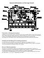
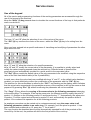
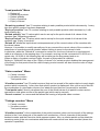
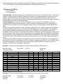
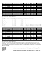
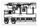
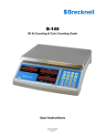
Cod. 2850020 - Rev. 00 - Marzo 2009
LP25 / LP30
®
General Characteristics
Sales of products
The board is predisposed for direct connection to a maximum of 8 trays with 9 spirals per tray.
The correct dispensing of the product is assured by the patented system which controls the rotation
of the spirals at 360° + X° -X° where X is programmable for each spiral.
The graphic display allows a simple and efficient use of the machine. The ample dimensions of the
display lend to a clear and detailed visualization of all texts with the possibility of contemporaneous
translations in a second language of your choice.
It is possible to personalize the operations on the display including visualization of the status
information, time and date, temperature and a maximum of 8 publicity Spots designed and
downloaded onto the machine by PC.
Accounts and registration
Each of the 72 possible products is equipped with a sales counter and a products remaining
counter. It is also possible to specify the valid days of each product to inhibit sales of expired
products.
The total sales counters allow the registration, even singularly, of each coin along with the direct
visualization in real currency.
The programming of the prices is also expressed in real currency with relative decimals and currency
symbols for an immediate understanding of the values of all costs.
The data-logger system allows the automatic registration of any machine operation. Up to more than
1700 records in text format allow the memorizing for each vend of the time and date, the number of
the selection, the remaining and actual takings, etc. A progressive reading system of these records
by PC allows the archiving on file, in unique mode, of the detailed information of each vend for the
whole life of the machine.
Clock functions
The clock/calendar of the logic board allows not only the eventual visualization of the current time
and date on the display and the registration of events using the data-logger, but permits the
management of turning on and off the refrigerator, the display cabinet and the display depending
on opportune programs. A maximum of 16 programs describe the operations of turning on and off by
correspondence masks which run from the value of the seconds to those annual.
Elevated programming and personalization
The RVM72A is the only electronic board where it is possible, by PC, to modify as required all the
texts in all the languages, the graphic fonts, the graphic icons, the Spots and the 3 default tables.
A computer software facilitates the reading, writing and archiving on file of all current working
parameters of the machine, in alternative to the manual programming with the keypad and display.
By PC it is also possible to update the software of the microprocessor directly onto the board.
Total compatibility of the board
The logic board RVM72A is mechanically and electrically compatible with the DRF35A board except
for the display which is substituted by a dimensionally bigger graphic display.
General Information on the logic board
Connection of the payment systems
A parallel coin mechanism can be connected to the 10 pin connector CN6 or to the 16 pin connector
CN5. These connectors supply, respectively, a power supply of 12V and 24V to the coin mechanism.
A serial coin mechanism with Executive protocol can be connected to connector CN8.
The parallel coin mechanism can be used contemporaneously with the serial coin mechanism.
Verifying and modifying of the working parameters
To enter the service menu press the “service key” indicated in the diagram for circa 1”.
To return to the normal state of vending of the machine press again this key or digit on the keypad
“Esc” (9) and confirm the selection with the “OK” (8) key.
Set up of default parameters
The board, for its functioning, avails of circa 800 different working parameters. Normally it is
necessary to modify only a few depending on specific needs. However, it is possible to automatically
re-install these parameters with the values contained in 3 distinct default tables.
To set-up one of the default tables you must turn the machine on whilst pushing down the “service
key” and the key “1” or “2” or “3” depending on the table.
Service menu
Use of the keypad
All of the service and programming functions of the working parameters are accessed through the
use of the keypad of the machine.
Keep the “Help” (3) key pressed down to visualize the current functions of the keys in that particular
menu or sub-menu:
The keys “1” and “2” allow the selection of one of the voices of the menu.
The “OK” (8) key confirms the choice of the menu, whilst the “Esc” (9) key is for exiting from the
menu.
Once you have entered into a specific sub-menu of visualizing and modifying of parameters the other
keys come into use:
Keys “1” and “2” allow the selection of a specific parameter.
Keys “4” and “5” modify the current value of the parameter. It is possible to quickly select and
modify the values keeping pressed down the relevant key. Different levels of speed will be
progressively and automatically recalled for a quick arrival to the requested value.
The “Def” (6) key recalls the default value of the only parameter to be modified, using the respective
value of the last used default table (of the 3 possibilities).
In each case, when the value has been modified with keys “4” and “5”, or the default value has been
recalled, you must definitively confirm the modification of the parameter with the ”OK” (8) key.
The attention for this confirmation is called by the “OK ?” text flashing on the display which indicates
that the actual value memorized in the parameter memory of the machine is still not the same as that
prepared. By pressing “Esc” (9) without confirming the parameter will not be modified.
The “Copy” (7) key allows the copying of the same value to the following parameters belonging
to the same group. For example, to set-up the same price for different products, modify the price of
product 11, position on the following product 12 and press the key “7”. Automatically, the same price
of product 11 will be copied and confirmed to product 12 and automatically the position shifts to
product 13 to continue this operation for all the following products.
An analogue procedure can be carried out to contemporaneously copy the same value to all
following parameters relative to an entire tray. For example, once the price for product 11 has
been modified and positioned on 12, press key “7” for at least 1”.
The copy function as described above will be automatically repeated for all of the products of the
current tray. At the end, the position will shift to the first product of the next tray.
“Load products” Menu
Reload all
Remaining products
Reload quantity
Expiry of products
Expiry of reload
“Remaining products” has 72 counters relating to each possible product which decrease by 1 every
time that specific product has been dispensed.
“Expiry of products” has 72 counters relating to each possible product which decrease by 1 with
each passing day.
“Reload quantity” has 72 values which can be set-up for the quick reload of all values of the
counters type “Remaining products”.
“Expiry of reload” has 72 values which can be set-up for the quick reload of all values of the
counters type “Expiry of products”.
“Reload all” allows the rapid reload contemporaneously of the current values of the counters with
the reload values.
However, it is possible to modify manually and in any moment the current values of the counters to
adapt them to a particular actual situation without having to resort to the reload in bulk.
In particular, when the “Reload all” command is carried out, the time of reload is re-synchronized,
used as a reference to the passing days. For example, carrying out this command at 16:30:00 on a
certain day, 16:30:00 of the following day will be taken as one day passed and so on.
When an expiry of product reaches 0 days, the sale of this product is inhibited.
Setting to “Unlimited” the days of the “Expiry of reload” of a certain product disables the management
of the expiry for that product and the relative expiry product counter will also show the value of days
“Unlimited”.
“Sales counters” Menu
Cancel counters
Visualize counters
Total partial sales
“Visualize counters” has 72 partial counters (that can be zeroed) of the sales relative to each single
product which increase by 1 every time that specific product is dispensed. Also, at the end of this list
the visualization of a total sales counter of an absolute type (that can’t be zeroed) is available.
“Total partial sales” directly visualizes the sum of the actual values of all partial counters and so
represents a total sales counter of the partial type (which can be zeroed).
“Cancel counters” is a command that allows the zeroing of all partial sales counters.
“Takings counters” Menu
Cancel counters
Visualize counters
Total partial takings
“Visualize counters” is the combination of the partial counters (which can be zeroed) of the takings
relative to the 6 coin channels of the parallel coin mechanism, of the 4 channels of the parallel
banknote reader and the Executive serial payment system. Also, an ulterior partial counter totals the
remaining costs of the coin mechanism and banknote reader which have been annulled (where this
operation is qualified).
At the end of this list is available the visualization of a total counter of the takings of an absolute type
(which can’t be zeroed).
“Total partial takings” visualizes directly the sum of the actual values of all partial counters and thus
represents a total counter of the partial type takings (which can be zeroed).
“Cancel counters” is a command that allows all the partial counters of the takings to be zeroed.
“Counters information” Menu
Cancel counters
Visualize counters
“Visualize counters” is an amalgamation of all partial counters (that can be zeroed) of the recurring
possible anomalies which can occur during the working of the machine.
The visualization of an absolute total counter is also available (which cannot be zeroed) of the
working time of the espresso machine in seconds with a 10 minute (600”) resolution.
“Cancel counters” is a command which allows the zeroing of all partial anomaly counters.
“Product prices” Menu
This menu allows the set-up of prices in real currency of all 72 possible products. It should be noted
that the values can be varied by quantity equal to the base coin, making it important to select in the
correct mode this unit.
There are two special price values indicated by “free” and “not used” included in the list between
maximum price and minimum price. In particular the “free” price allows the selling of that product
even in the absence of credit, whilst the “not used” price disables the sale of that specific product.
“Config. product” Menu
Spiral Rotation
Lift quote
Disk machine
With this menu it is possible to configurate the parameters and the options relating to the dispensing
of the product.
“Spiral rotation” contains the 72 values relative to the extra rotation of the spirals. The patented
“System” permits the rotation of the spiral superior to 360°, programmable for each spiral. After this
extra rotation, the spiral inverts direction and returns exactly to 360°. An automatic control system
allows to bring the spiral under phase in the event of, for example, a power cut during the rotation.
“Lift quote” allows the modification of the position of the (optional) lift in correspondence to the trays
in the machine.
“Disk machine” contains the parameters relative to the use of the logic board for disk machines, not
spiral ones. In this menu only the option to activate the double impulse is available.
“Config. Coin mechanism” Menu
General config.
Parallel coin mechanism
Executive coin mechanism
“General config.” Gathers all parameters relative to the payment systems that are commune to all
types of coin mechanism. In this submenu is the free sale option for all products, the value of the
base coin, the number of decimals and the currency symbol to be used in the visualization of all
costs.
“Parallel coin mechanism” is the amalgamation of values, in real currency, relative to the 6 coin
channels of the parallel coin mechanism and the 4 channels of the parallel banknote reader.
There is also available the option of automatic annulment of the remaining credit (only from parallel
systems and not executive systems) with relative zeroing time.
“Executive coin mechanism” allows the activation of the “Price Holding” option of the Executive
payment systems. It is also available the programming of the 72 “price lines” relative to all possible
products. Remember that the value of the “price lines” is a value relayed to the Executive system (to
identify the product) in alternative to the effective value of the price only when the “Price Holding”
option is activated.
In this way the coin mechanism, noting the requested product, determines the real price of sale
through its price table. It is necessary to set-up the same prices on the logic board of the machine
(with the relevant menu) as set up on the coin mechanism just for the correct visualization and
management of the sale.
“General config.” Menu
This menu unites different parameters of configuration of various parts and functioning of the
machine.
We have the activation of the refrigerator group with relative set-up of the temperature and the
option to block sales in the event of the temperature being too high in respect of that programmed.
It is possible to program the principal language of the display and activate an eventual second
language of choice to visualize the contemporaneous translation of all texts present during a sale.
It is also possible to personalize the visualization of the graphic display during a sale.
In particular you can deactivate the current credit visualization in the sales scheme, activate the
temperature visualization and activate the date/time visualization. All of these visualizations, and
other eventual warning signs that can appear in particular situations, appear in sequence and with a
time programmable from the “Time visualiz. Status” parameter.
A characteristic of the board is that to alternate the previous sequence of the status scheme with a
certain number of “Spots” . These are full screen graphic images which can be designed using any
graphic program on a PC. You will need to create a file for each Spot of the BITMAP type,
monochrome with resolution 128x64 and download to the board using the relevant software on a PC
with a normal serial cable RS232. At this point it is enough to program the number of seconds of
visualization requested for each Spot. Up to 8 Spots can be downloaded to the board and kept at
disposition for activation on particular occasions.
Available in this menu are other parameters such as an identity number for the machine and a
communication address for the programming portal (for the management of more than one
machine with the same PC or other method of external supervision).
The “Machine model” parameter must be programmed depending on the particular machine so that
the board can manage in the appropriate way all specific functions.
The “Operator Code” permits a number to be programmed to be used as a password for access to
the machine menu. A code equal to 0 deactivates the request for the password whilst it is possible to
insert a number using all 10 numbers from 0 to 9. When the password is requested the keypad can
be used to digit the value directly. The keys from 1 to 5 have a second function when the “Shift” (7)
key is pressed:
Note: entering the principal service menu with the appropriate key when a password has been
programmed, the introduction of the code is requested. Here there are two possibilities. Pressing
directly “OK” (8) enters the principal menu without password and in this case certain menus will not
be accessible without later inserting the password. Instead, inserting the correct password using keys
“1”-“5” and “Shift” all menus will be accessible up to exiting the service menu.
“Clock set-up” Menu
Set time/date
On/off programs
“Set time/date” allows the regulation of the date and current time on the machine clock. This clock is
used for various machine functions. Apart from visualizing in the pause between vends, the clock is
used to update the expiry of the products (when used), to manage the turning on and off of the
different parts of the machine according to certain programs and to provide the data-logger records of
the time/date information on particular events.
“On/off Programs” contains a list of 16 programs to turn on and off the refrigerator group, the
display case illumination and the display. If the illumination has been turned off by a program, it is
possible to momentarily turn it back on again pressing any key on the keypad and thus allowing a
vend.
Each on/off program consists of a total of 8 fields of which the first 7 identify a particular condition of
time/date whilst the last is of the on/off status desired departing from that time/date. The programs
are constantly verified departing from program 1 up to program 16. All programs in which the
time/date is verified (the current time/date is the same or more than that of the program excepting the
field “Day of the week” which requires the program only of equality) define as valid their on/off status.
Consequentially, if more programs see their condition of time/date verified, the valid on/off status will
be that of the last verified program and so the priority is more as much as the number of programs is
more.
In defining the time/date condition of a program the use of the value “whichever” is very important to
specify that that field is not important for that condition. Programming the field “Year” to 2099 makes
the relevant program un-influential in that, independent of other fields, the condition will not be
verified until 2099. Some examples of programs:
Example 1. Needs a weekly program the same for all the weeks of all the years:
Monday-Friday
Saturday-Sunday
Prog.
1
2
3
4
5
6
7
8
9
10
11
12
13
14
15
16
Day of the week
*
*
Saturday
Sunday
*
*
*
*
*
*
*
*
*
*
*
*
from 8:30
to 18:30
Day of the month
*
*
*
*
*
*
*
*
*
*
*
*
*
*
*
*
Month
*
*
*
*
*
*
*
*
*
*
*
*
*
*
*
*
all access
all off
Year
*
*
*
*
2099
2099
2099
2099
2099
2099
2099
2099
2099
2099
2099
2099
Hour
8
18
*
*
*
*
*
*
*
*
*
*
*
*
*
*
Minute
30
30
*
*
*
*
*
*
*
*
*
*
*
*
*
*
Note: the character * signifies “Whichever”.
Example 2. Needs a weekly programming the same for every week of every year:
Monday-Friday
Saturday
Sunday
from 8:30
from 9:30
to 18:30
to 13:30
all access
all access
all off
Sec.
*
*
*
*
*
*
*
*
*
*
*
*
*
*
*
*
Status on/off
ON-ON-ON
OFF-OFF-OFF
OFF-OFF-OFF
OFF-OFF-OFF
*
*
*
*
*
*
*
*
*
*
*
*
Prog.
1
2
3
4
5
6
7
8
9
10
11
12
13
14
15
16
Day of the week
*
*
Saturday
Saturday
Saturday
Sunday
*
*
*
*
*
*
*
*
*
*
Day of the month
*
*
*
*
*
*
*
*
*
*
*
*
*
*
*
*
Month
*
*
*
*
*
*
*
*
*
*
*
*
*
*
*
*
Year
*
*
*
*
*
*
2099
2099
2099
2099
2099
2099
2099
2099
2099
2099
Hour
8
18
*
9
13
*
*
*
*
*
*
*
*
*
*
*
Minute
30
30
*
30
30
*
*
*
*
*
*
*
*
*
*
*
Sec.
*
*
*
*
*
*
*
*
*
*
*
*
*
*
*
*
Status on/off
ON-ON-ON
OFF-OFF-OFF
OFF-OFF-OFF
ON-ON-ON
OFF-OFF-OFF
OFF-OFF-OFF
*
*
*
*
*
*
*
*
*
*
Note: the character * signifies “Whichever”.
Example 3. Needs a weekly programming the same for every week of every year:
Monday
Tuesday
Wednesday
Thursday
Friday
Saturday
Sunday
Prog.
1
2
3
4
5
6
7
8
9
10
11
12
13
14
15
16
Day of the week
Monday
Monday
Tuesday
Tuesday
Wednesday
Wednesday
Thursday
Thursday
Friday
Friday
Saturday
Saturday
Sunday
Sunday
*
*
from 8:00
from 8:15
from 8:30
from 8:45
from 9:00
from 9:15
from 9:30
Day of the month
*
*
*
*
*
*
*
*
*
*
*
*
*
*
*
*
to 16:00
to 16:15
to 16:30
to 16:45
to 17:00
to 17:15
to 17:30
Month
*
*
*
*
*
*
*
*
*
*
*
*
*
*
*
*
all access
all access
all access
all access
all access
refrigerator ON,display case/display OFF
refrigerator ON,display case/display OFF
Year
*
*
*
*
*
*
*
*
*
*
*
*
*
*
2099
2099
Hour
8
16
8
16
8
16
8
16
9
17
9
17
9
17
*
*
Minute
0
0
15
15
30
30
45
45
0
0
15
15
30
30
*
*
Sec.
*
*
*
*
*
*
*
*
*
*
*
*
*
*
*
*
Status on/off
ON-ON-ON
OFF-OFF-OFF
ON-ON-ON
OFF-OFF-OFF
ON-ON-ON
OFF-OFF-OFF
ON-ON-ON
OFF-OFF-OFF
ON-ON-ON
OFF-OFF-OFF
ON-OFF-OFF
OFF-OFF-OFF
ON-OFF-OFF
OFF-OFF-OFF
*
*
Note: the character * signifies “Whichever”.
Consider that the on/off status associated with a program is represented by 3 icons (one for the
refrigerator, one for the illumination of the display case and one for the illumination of the display).
The on/off status of the program corresponds to one of the 8 possible combinations of access/off of
all 3. For example:
indicates respectively: refrigerator ON, display case ON, display ON
indicates respectively: refrigerator ON, display case OFF, display OFF
“Test machine” Menu
Test trays
Test lift
Test flap
Test optical sensor
“Test trays” consents the cyclical testing of all the spirals of all the trays. Remember that all spirals
for which the price is set at “Not used” are excluded from the test.
“Test lift” continually tests the lift where this option is available.
“Test flap” opens and closes continually the protection flap in the retrieval window.
“Test optical sensor” allows to verify the manual simulation of the passing of the product in front of
the optical sensor where this option is present.
To end any test press the “Esc” (9) key.
Other functions of the logic board
Data-logger of events
The board avails of an automatic register of events. The events are memorized in the form of lines of
text in the internal of which there is different useful information on the event itself. Connecting a
Personal Computer to the CN1 connector for programming the board using a standard serial cable it
is possible to read this information and save it to a text file.
Normally, each event is a line of text in the file.
An example of 4 events follows:
1
2
3
4
22/04/2006
22/04/2006
22/04/2006
22/04/2006
15:29:56
15:29:58
15:30:24
15:30:42
SERVICE:
SERVICE:
VEND:
VEND:
Enter
Exit
Product=11 Vends=1
Product=12 Vends=1
Stock=13
Stock=13
Abs_Takings=10
Abs_Takings=20
Abs_Vends=1
Abs_Vends=2
Temp=12.5°C
Temp=12.4°C
Each record begins with a progressive number of identification of the event followed by the time and
date of registration of said event.
The next column represents the type of event. In this example the event number 1 indicates a service
entry of the board whilst event number 2 relates to the exiting from the service menu.
Successively, the machine has sold with success product number 11. After this sale, the partial sales
counter of the specific product is raised by 1 whilst the product availability counter descends from the
full load of 14 to 13. The absolute counter of takings has totalized 10 base coins, whilst the absolute
sales counter has totalized 1. Also, during that particular sale the temperature of the refrigerator was
12.5°C.
It results obvious also the description of the following sale effected on product number 12.
The sale of a product is definitely the most recurrent event in the machine. However, many other
events are registered, such as the turning on of the machine and all possible verifiable anomalies.
Registration of events is autonomous and automatic and the board is capable of memorizing more
than 1700 events (lines) in its permanent memory. The mechanism of registration is equivalent to that
of a continuous tape so that, reaching the registration of the maximum number of events, new
records will successively take the place of the older ones.
To keep track of all events for the entire life of the machine it is necessary to download periodically
with a PC the contents of the memory of the data-logger. The software on the PC will save the
current contents of the register on a text file, automatically assigning a name composed of an
arbitrary text added to the machine number and the time/date of acquisition. In this way, every
acquisition file will be unique, as will be the identity number of each event of the machine. In this way,
it is possible to archive on a PC the data-logger files and keep track of each single sale of each
machine installed for the duration of said machine.
Programming by Personal Computer
The CN1 programming connector constitutes a serial portal RS232 of access to the board (and thus
to the machine) with enormous potential.
This communication portal consents principally to read and write all the circa 800 work parameters of
the machine. In this way, it is possible to set-up the functioning of the machine contemporaneously or
alternatively to the use of the keypad and display. Having read the parameters of the machine it is
possible to modify them and re-transfer to same. Also, the parameters taken can be saved to file and
vice versa it is possible to recall from a file a certain batch of values of the parameters to then
transfer to the machine. In this way the optimum parameters can be archived to a PC by file (for
example using a different name for each machine) to be re-used to configure other machines.
By PC it is also possible to set-up the clock of the machine or read, save to file and visualize the
contents of the data-logger.
An innovative characteristic of the board is the possibility to modify and personalize all the graphic
images which appear on the display. In particular, amongst these images, there are 8 Spots which
can be used for publicity, warnings and information of all types. The Spots are full screen graphic
images which require the creation of such files as BITMAP monochrome with resolution 128x64.
Programs of image elaboration can be used for their creation (from a simple PAINT to more
sophisticated programs such as PhotoImpact). After an opportune operation of conversion, these files
can be transferred to the board by a serial portal.
With an analogue procedure all texts (in the various languages) visualized on the display can be
modified. This time it is necessary to modify a text file in standard Unicode format. The choice of the
Unicode format is decided by the necessity to use a batch of possible characters belonging to Latin,
Common Latin, Cyrillic and Greek.
For all precedent programming and personalization functions you will just need a PC with Windows
operative system, the software equipped with RVM72A and a standard serial cable. For PC’s with
just a USB portal, standard commercial adaptor cables USB-RS232 can be used.
Also by PC, it is possible to update the Firmware of the microprocessor of the board, or more
precisely the software for the functioning of same developed and periodically updated. Just for this
update it is necessary to connect a PC to the CN11 connector of the board using the appropriate
interface available as an optional.
CAB1 BOARD
COOLER GROUP
COMPRESSOR
FAULT LED
LINE
1A
L
PE
N
230V
FAULT LED
SOLDERED WIRES
R
3
L
4
6A
1
NEON+BOARD FUSE
M
COOLER FUSE
2
PE
2
N
1
M
C
M
12A
3
MAIN FUSE
INTERNAL FANS
3 POLES
CONDENSER
FAN
6 POLES
22V LED
FAULT LED
TEMPERATURE
SENSOR
SOLDERED WIRES
1
4 POLES
2 POLES
2
1
2
4
3
12 POLES
9
11
12
10
1
3
1
9
8
3
9 POLES
7
GND
+5V
OUT
11V LED
RELAY COIL
LCD72A DISPLAY
KEY9B KEYBOARD
6
4 POLES
5
1
1
2
3
22V
3
230V
SWITCH
11V
TRANSFORMER
1
2
3
4
5
6
7
8
9
10
11
12
13
14
DISPLAY CONTRAST
STATIC RELAY
M56
VENDING
MOTORS
6
8
7
FRE
5
4
2
1
10 POLES
PARALLEL COIN ACCEPTOR
4
5
-RX
-RX
3
NC
+RX
+TX
2
1
+TX
-TX
-RX
+RX
16
+24V
16
14
13
15
NC
15
NC
COIN1
13
16 POLES
PARALLEL COIN ACCEPTOR
14
11
10
12
COIN2
12
COIN6
11
COIN5
9
CN8
10
8
GND
COIN4
9
8
6
7
COIN3
NC
6
7
5
4
NC
NC
5
4
3
NC
3
1
2
NC
NC
1
2
9
10
COIN4
10
8
COIN2
COIN3
9
8
6
7
COIN1
NC
6
CN5
7
4
3
5
NC
5
COIN6
COIN5
3
4
1
2
+12V
GND
1
2
8
+12V
+12
7
6
+12V
GND
GND
+12
4
5
NC
BILL4
3
B3
B4
BILL3
1
2
BILL2
BILL1
B1
B2
9
10
GND
+M
9
10
8
+M
CN6
PARALLEL
BILL ACCEPTOR
IM7A
M
CN7
8
7
M1
7
6
M2
6
5
M3
5
3
4
M4
M5
3
4
1
2
M6
M7
1
2
9
10
GND
10
8
+M
+M
9
8
6
7
M1
M2
6
7
4
3
5
M3
5
M4
M5
3
4
1
2
M6
M7
1
2
CN23/CN15
M11
9 POLES
CN12
VENDING CONTROLLER
RVM72A
IM7A/IM11A
INTERFACES
M
4 POLES
CN9
CN30/CN22
IM7A
3
POWER SUPPLY
CN4
8 X MOTOR CONNECTORS
M16
4
+12V
NC
NC
NC
CANC
START
*
6
5
4
3
2
1
GND
GND
1
2
3
4
5
6
7
8
9
10
11
12
13
14
CN13
GND
+5V
SIGNAL
NEON GROUP
S
EXECUTIVE
CHANGER
M51
M
M
NOTE: CONNECT IM7A TO CN23-CN30 FOR 6 SPIRAL
CONNECT IM11A TO CN15-CN22 FOR 7-9 SPIRAL
MACHINE ELECTRICAL SCHEME
Cod. 2850020 - Rev. 00 - Marzo 2009
LP25 / LP30
®