1
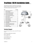
TracVision M3
Installation Guide
TracVision M3 Installation Guide
®
These instructions explain how to install the TracVision M3 satellite TV antenna
system on a vessel. Complete instructions on how to use the system are provided in
the Quick Start Guide and Receiver User’s Guide.
Who Should Install the System?
To ensure a safe and effective installation, KVH recommends that a KVH-authorized
marine technician install the TracVision M3 system. To find a technician near you, go to
www.kvh.com/wheretogetservice. If you purchased the product and decide to install it
yourself, please see the enclosed warranty statement for warranty implications.
Important Safety Precaution
DO NOT apply power to the TracVision antenna with the radome removed
because the antenna has moving parts that can cause injury.
CAUTION
Receiver Activation
Once the system is fully installed, the owner needs to call
KVH’s Activation Department to activate the receiver for
DIRECTV® service:
Toll-free at 1-866-551-8004
051099999
051077777
The owner will need the red Activation Card when
calling to activate. In addition, the antenna will need to
be turned on and locked onto the satellite. See page v of
the Receiver User’s Guide for details.
Technical Support
If you need technical assistance, please contact KVH Technical Support:
Phone:
1-401-847-3327
E-mail:
[email protected]
Internet:
www.kvh.com/help
KVH and TracVision are registered trademarks of KVH Industries, Inc.; DIRECTV is a registered trademark of DIRECTV, Inc.
The information in this document is subject to change without notice. No company shall be liable for errors contained herein.
54-0274-01 Rev. A
1
© 2005 KVH Industries, Inc., All rights reserved.
1 Inspect Parts and Get Tools
1. Unpack the box and ensure it contains
everything shown on the Contents List. Save
the packaging in case you need to reship the
system.
Antenna
Radome
2. Carefully examine all of the supplied parts to
ensure nothing was damaged in shipment.
Base
Always lift the antenna by the
silver base and never by the
radome or any portion of the
internal antenna assembly.
Receiver
Connector
Cover
3. Gather all of the tools and materials listed
below. You will need these items to complete
the installation.
• #2 Phillips screwdriver
•
7
•
7
•
⁄2" socket or open-end
wrench
⁄16" open-end wrench
⁄16" socket wrench
1
• Electric drill
•
⁄16" (8 mm) drill bit
5
• Hole saw of desired diameter
(for cable access hole, see page 4)
• Adhesive tape
• Light hammer
• Center punch
• Four 1⁄4" fasteners
(optional for mounting the receiver,
see page 10)
• Silicone sealant or
equivalent
4. Peel off the extra serial number label (taped to
the antenna) and affix it in the appropriate
box on the red Activation Card.
051099999
54-0274-01 Rev. A
2
Affix Serial
Number
© 2005 KVH Industries, Inc., All rights reserved.
2 Plan the Installation
Before you begin, consider the following installation guidelines:
• Minimize blockage. The antenna requires a
clear view of the sky to receive satellite TV.
The fewer obstructions above decks, the
better the system will perform.
• When choosing a mounting surface, ensure
it is wide enough to accommodate the
antenna’s base. See illustrations for antenna
dimensions.
Antenna
Blocked!
Radar
• Ensure the mounting surface is flat, level
(within ±2º), and strong enough to support
the 18-pound antenna. Use a separate
mounting plate, if necessary.
Vessel Platform
• Custom mounting solutions, including
struts and masts, are available from several
third-party manufacturers. Contact your
local KVH dealer for details.
17.32"
(44 cm)
• KVH recommends that you do not mount
the antenna on the same level as the radar,
because the radar’s energy might overload
the antenna.
• Be sure to mount the antenna near enough
to the supplied belowdecks receiver to
allow you to connect the 50-ft. (15 m) coax
cable between the antenna and the receiver,
while still maintaining sufficient slack in
the cable. The antenna cable CANNOT be
extended.
• When choosing a location for the receiver,
find a dry, well-ventilated area belowdecks
away from any heat sources. Also be sure
the receiver’s front panel will be easily
accessible to the user and the three lights on
the top of the receiver will be visible.
54-0274-01 Rev. A
3
15.5"
(39.37 cm)
9.2"
(23.37 cm)
FWD
4.6"
(11.68 cm)
4 x 0.31"
( 0.79 cm)
2.8"
(7.11 cm)
5.6"
(14.22 cm)
© 2005 KVH Industries, Inc., All rights reserved.
3 Prepare the Mounting Site
Antenna Base
15.5"
(39.4 cm)
1. Unfold the supplied template
and place it onto the mounting
surface. Make sure the “FWD”
(forward) arrow points toward
the bow and is parallel to the
vessel’s centerline. You do not
need to mount the antenna exactly
on the vessel’s centerline, but the
antenna’s forward arrow must be
parallel to it.
2.8"
(7.1 cm)
X
5.6"
(14.2 cm)
2. Use the template to mark the
four hole locations on the
mounting surface.
4 x 0.31"
( 0.8 cm)
Mounting Holes
3. Drill a 5⁄16" (8 mm) hole at the
four locations you marked in
Step 2. Later, you will insert four
1
⁄4"-20 bolts from above to secure the
antenna to the mounting surface.
4.6"
(11.7 cm)
Cable Access Hole
(Suggested Location)
9.2"
(23.4 cm)
4. Mark a location for the cable access
hole, either in the center of the
antenna mounting hole pattern or in
an area aft of the antenna. Later, you
will route the antenna cable through
this hole and into the vessel.
Be sure the mounting surface is
flat and level. Use a separate
mounting plate, if necessary.
5. Drill the cable access hole in the
location you marked in Step 4. Be
sure to size the hole appropriately
to maintain a cable bend radius of
at least 3" (75 mm). If the hole location
is in the center of the antenna
mounting hole pattern, the diameter of
the cable access hole must not exceed
3.5" (88 mm). Smooth the edges of
the hole to protect the cable.
Drilling Antenna
Mounting Holes
54-0274-01 Rev. A
4
© 2005 KVH Industries, Inc., All rights reserved.
4 Wire the Antenna
1. Clean and dry the antenna mounting
surface.
2. Peel off the paper backing from the donutshaped foam seal to expose the adhesive.
Then press the foam seal down firmly onto
the mounting surface, centered between the
antenna mounting holes.
3. Using the supplied 3 mm Allen hex key,
remove the connector cover from the
antenna’s base. Save the cover and the four
M4 cap screws for later use.
Foam Seal
4. Route either end of the antenna cable into
the vessel. Later, you will connect this end of
the cable to the belowdecks receiver. You will
connect the other end to the antenna.
5. If you wish to route the cable beneath the
antenna, attach the right-angle connector to
the end of the cable. Hand-tighten, then
tighten with a 7⁄16" wrench for 1⁄4 turn to
ensure an electrical and weather-proof
connection
6. Connect the cable to the antenna. Handtighten, then tighten with a 7⁄16" wrench for
1
⁄4 turn. Rigging tape is recommended to protect
the connector.
Connector Cover
Right-angle
Connector
7. Reattach the cover over the connector.
Secure in place with the M4 cap screws you
removed in Step 3. The cover must be
attached before you mount the antenna.
8. Leave an adequate service loop,
approximately 8" (20 cm) of slack, in the
antenna cable for easy serviceability.
9. Seal the cable access hole with silicone
sealant or equivalent.
54-0274-01 Rev. A
Antenna Cable
5
© 2005 KVH Industries, Inc., All rights reserved.
5 Mount the Antenna
1. Remove the three #10-32 screws securing
the radome to the antenna. Carefully
remove the radome and set it aside in a safe
place. Due to the snug fit, some contact
between the radome’s sealing gasket and the
antenna mechanism is normal.
“Forward” Arrow
2. Position the antenna onto the mounting
surface. The antenna’s base should rest
squarely atop the foam seal.
3. Align the four holes in the antenna’s base
with the four holes in the mounting surface.
Be sure the antenna’s “Forward” arrow
points toward the bow.
4. Secure the antenna’s base to the mounting
surface using four 1⁄4"-20 bolts, 5⁄8" washers,
1" washers, and lock nuts, as shown in the
illustration. Be sure to insert the bolts from
above and use the supplied hardware for a
secure installation.
5. Tighten the bolts until the foam seal is fully
compressed and the antenna’s four rubber
feet are bottomed against the mounting
surface.
Insert the mounting bolts into
the antenna’s base from above,
not below.
1/4"-20 x 3" Bolt
1/4" Flat Washer
(5/8" diameter)
Antenna Base
Foam Seal
Mounting Surface
1/4" Flat Washer
(1" diameter)
1/4"-20 Lock Nut
Tighten Bolts
from Above
54-0274-01 Rev. A
6
© 2005 KVH Industries, Inc., All rights reserved.
6 Remove the Restraints
1. Using a 7⁄16" socket wrench, remove the two
bolts securing the antenna assembly to the
base. Be sure to remove both of these
shipping restraints, along with the washers
and spacers. Save the restraints for future use.
Shipping Restraints
Bolt
Washer
Spacer
2. Reinstall the antenna radome. While
pressing the radome down onto the base,
secure the radome to the base using the three
#10-32 screws you removed earlier. The
radome’s “TracVision” labels should face fore
and aft.
3. Install a protective plastic screw cap (supplied
in the kit) over each radome screw.
Be sure to remove both shipping
restraint bolts, washers, and
spacers. The antenna will not
work with these restraints still
installed.
Antenna Mounted
Antenna
Radome
54-0274-01 Rev. A
7
© 2005 KVH Industries, Inc., All rights reserved.
7 Wire the Receiver
1. Connect the antenna cable (A) to the “To KVH
Antenna” jack. Do not kink/stress the cable.
Do not shorten or extend
the antenna cable. Since the
antenna cable carries data,
power, and communications,
the integrity of this cable
and its connections is very
important.
2. Connect the RF converter cable (B) to the “RF
Remote Input” jack.
3. Connect the receiver to the vessel’s entertainment
system (TV). Choose one of the following options:
Be sure to route cables within the vessel appropriately to
avoid damage. For example,
do not route any cables
through wet areas (bilges) or
near hot exhaust pipes.
Option 1 - RCA-type A/V jacks (use bottom row)
Option 2 - S-Video jack (provides best picture quality)
Option 3 - RF coaxial connector
Cables for option 1 are included in the kit.
4. (Optional) If you have a VHF TV antenna onboard,
you can connect it to the “VHF Antenna In” jack on
the receiver. If you connect a VHF antenna to the
receiver, you need to use the receiver’s RF coaxial
connector (option 3) to supply VHF video to the TV.
5. Be sure to tighten all connections. Also be sure to
leave enough slack in the cables (service loop) for
easy serviceability, allowing you to access the
receiver’s rear panel with the cables connected.
Antenna
For details on connecting an additional receiver,
please see Appendix A in the Receiver User’s Guide.
Deck
(A)
Service/
Maintenance
Only
To VHF Antenna
(Optional)
Do not disconnect the
short cable on the back
of the receiver.
C AU T I O N
VHF ANTENNA
IN
TO SATELLITE
IN
VEHICLE POWER
(10-16 VDC)
TO KVH
ANTENNA
SATELLITE IN
DIAGNOSTICS
PORT 1
DIAGNOSTICS
PORT 2
This device complies with Part 15 of the FCC rules. Operation is subject
to the following two conditions: (1) This device must not cause harmful
interference, and (2) This device must accept any interference received,
including interference that may cause undesired operation.
POWER
RF
REMOTE
INPUT
OUT TO TV
TUNER
AUDIO R
AUDIO L
Receiver
VIDEO
S – VIDEO
PHONE JACK
Tested to comply
with FCC Standards
To Video
(Option 2)
(B)
RF Converter
54-0274-01 Rev. A
To Video
(Option 3)
8
To Audio
To Video
(Option 1)
© 2005 KVH Industries, Inc., All rights reserved.
8 Connect Power
The receiver requires a 10-16 volts DC (VDC) power
input supporting 50 watts (4.2 amps @ 12 VDC).
For your own safety, shut
down vessel power before
you connect the wires.
1. Before you connect the receiver’s power wires,
turn off vessel power and test the circuit to
ensure no power is present.
2. Connect the receiver’s individual power wires to
a dedicated 10-amp or 15-amp circuit breaker.
Connect the negative (black) wire to ground
(power return), and connect the positive (red)
wire to +12 VDC vessel power.
3. Plug the other end of the power wires into the
“Vehicle Power” jack on the receiver’s rear panel.
Do not remove the small ferrite coil that is clamped
onto the power wires. This coil suppresses EMI
(electromagnetic interference) from the receiver.
Fuse (6 amp)
Vessel Power
(10-16 VDC)
DC Power
Ground
Ferrite
Coil
C AU T I O N
VHF ANTENNA
IN
TO SATELLITE
IN
VEHICLE POWER
(10-16 VDC)
TO KVH
ANTENNA
SATELLITE IN
RF
REMOTE
INPUT
DIAGNOSTICS
PORT 1
DIAGNOSTICS
PORT 2
This device complies with Part 15 of the FCC rules. Operation is subject
to the following two conditions: (1) This device must not cause harmful
interference, and (2) This device must accept any interference received,
including interference that may cause undesired operation.
POWER
OUT TO TV
TUNER
AUDIO R
AUDIO L
VIDEO
S – VIDEO
PHONE JACK
Tested to comply
with FCC Standards
Receiver
54-0274-01 Rev. A
9
© 2005 KVH Industries, Inc., All rights reserved.
9 Install the Receiver
Once all cables are connected,
install the receiver inside the
vessel.
To avoid overheating,
do not block the
receiver’s vents.
1. If you wish to mount the
receiver, attach the two
mounting brackets to the
sides of the receiver using three
#2-56 screws. Simply screw these
fasteners into the receiver’s vent slots.
1⁄4" Fasteners (x4)
(not supplied)
Bracket
#2-56 x 1⁄4" Screws (x3)
2. If you are using the mounting
brackets, secure the brackets to the
mounting surface using appropriate
1
⁄4" fasteners (not supplied).
3. Place the RF converter at least 3 feet
(1 meter) away from the receiver. If it
is too close to the receiver, the remote
control might not operate properly.
Also avoid placing the RF converter
behind a metal surface or in an area
surrounded by metal.
Receiver Mounted
Plug into
Receiver
(see page 8)
4. If desired, mount the RF converter
using the supplied Velcro fasteners.
RF Converter
10 Install Batteries in Remote
1. Remove the battery compartment cover from
the back of the remote control.
2. Insert two AAA batteries (supplied in the kit).
Be sure to observe the correct polarity.
AAA Batteries
3. Replace the battery compartment cover.
54-0274-01 Rev. A
10
© 2005 KVH Industries, Inc., All rights reserved.
11 Test the System
Now all you need to do is turn the system ON
and ensure everything works properly.
1. Ensure the antenna has a clear view of the
southern sky.
Power Switch
2. Apply power to the TV and the TracVision
system.
VHF ANTENNA
IN
VEHICLE POWER
(10-16 VDC)
POWER
3. Turn on the power switch on the receiver’s
rear panel.
SATELLITE IN
4. Wait while the antenna searches the sky for the
DIRECTV satellite. Once the antenna finds the
satellite, the receiver downloads the program
guide. A progress bar should display on your
TV. (It could take 60 seconds to load the program
guide, once it begins loading.)
RF
REMOTE
INPUT
OUT TO TV
TUNER
If your satellite dish is ready for DIRECTV®
service, please wait until your
Advanced Program Guide™ is prepared.
Installation
Acquiring guide data...
Only the DIRECTV preview channel
(channel 100) is viewable until the
owner activates the receiver.
Antenna Power
Button
If the system shuts off after 30 seconds, simply
press the “Antenna Power” button on the
receiver’s front panel.
5. Once a DIRECTV picture appears on the TV,
verify that the 3 status lights on top of the
receiver are lit green.
Status Lights
A - VOLTAGE Light
B - RECEIVER Light
A
B
C
C - ANTENNA Light
Refer to the Quick Start Guide and Receiver
User’s Guide for complete operation instructions
and troubleshooting information.
54-0274-01 Rev. A
11
© 2005 KVH Industries, Inc., All rights reserved.
Things the User Needs to Know
• Keep the radome installed on the
antenna at all times. The radome
protects the antenna’s internal moving
parts from wind, rain, and debris.
CAUTION: In the unlikely event
that you need to remove the
radome, remove power from the
antenna first because the antenna’s
moving parts can cause injury.
The owner needs the
red Activation Card to
activate the receiver.
051099999
051077777
• The receiver must be activated before it
can receive DIRECTV programming.
• The antenna tracks the DIRECTV 101W
satellite only. It cannot receive
programming from other satellite TV
service providers and it cannot receive
channels broadcast on other satellites.
• The antenna should be cleaned
regularly. Dirt buildup on the radome
can affect satellite TV reception.
• The antenna must have a clear view of
the southern sky to receive satellite TV.
Common causes of blockage include
trees, building, bridges, and equipment
on the vessel itself.
• The owner needs to register the system
for product warranty validation. Refer
to the Product Registration Form for
details or visit: www.kvh.com/register.
• It is dangerous to watch TV while
piloting a vessel.
• The vessel must be located within the
DIRECTV satellite’s coverage area in
order to receive satellite TV. To view a
satellite coverage map, visit:
www.kvh.com/footprint.
• The receiver beeps to indicate the
status of the antenna:
Two beeps = Antenna is powering on
One beep = Antenna is powering off
Blocked!
TracVision
• Refer to the Quick Start Guide and the
Receiver User’s Guide for complete
operation instructions.
• Heavy rain may temporarily interrupt
reception.
54-0274-01 Rev. A
12
© 2005 KVH Industries, Inc., All rights reserved.
www.kvh.com
KVH Industries, Inc. • 50 Enterprise Center • Middletown, RI 02842-5279 U.S.A . • Phone: (401) 847-3327 • Fax: (401) 849-0045 • E-mail: [email protected]
© Copyright 2005, KVH Industries, Inc.
KVH and TracVision are registered trademarks of KVH Industries, Inc.