1
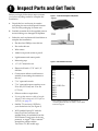
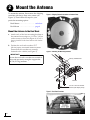
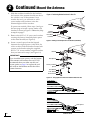
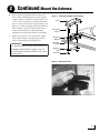
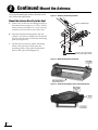
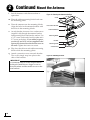
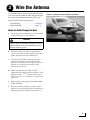
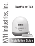
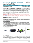
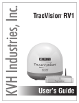
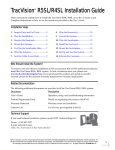
KVH Industries, Inc. TracVision A9 ® Installation Guide TracVision A9 Installation Guide This guide explains how to install the TracVision A9 satellite TV antenna system on a vehicle. Operation instructions are provided in the Quick Start Guide. Installation Steps 1. Inspect Parts and Get Tools ................. 3 8. Connect Power ..................................... 23 2. Mount the Antenna ............................... 4 9. Turn On the System............................. 25 3. Wire the Antenna ................................ 11 10. Access the Web Interface .................... 26 4. Plan the TV-Hub Installation ............. 16 11. Connect to an Existing Network ....... 27 5. Mount the TV-Hub.............................. 17 12. Secure the Wi-Fi Connection.............. 28 6. Wire the Antenna to the TV-Hub...... 18 13. Set Up the System ................................ 29 7. Wire the Receivers............................... 19 14. Educate the Customer......................... 31 Appendices A. Installing an IP AutoSwitch ............... 33 B. Using a DIRECTV Coax Network..... 36 Who Should Install the System? To ensure a safe and effective installation, KVH recommends that a KVH-authorized technician install the TracVision antenna. KVH-authorized technicians have the tools and electronics expertise necessary to install the system. To find a technician near you, visit www.kvh.com/ wheretogetservice. Technical Support If you need technical assistance, please contact KVH Technical Support: Phone: +1 401 847-3327 Email: [email protected] (Mon.-Fri., 9 am-6 pm; Sat., 9 am-2 pm ET, -5 GMT) KVH and TracVision are registered trademarks of KVH Industries, Inc. All other trademarks are property of their respective companies. The information in this document is subject to change without notice. No company shall be liable for errors contained herein. © 2014 KVH Industries, Inc., All rights reserved. 54-1079 Rev. A 1 Important Safety Information This icon indicates a danger, warning, or caution notice. Be sure to read these carefully to avoid injury. WARNING Risk of Electric Shock To avoid electric shock, do not open the TV-Hub chassis enclosure. There are no user-serviceable parts inside. WARNING Risk of Electric Shock If any component of the TracVision system becomes damaged and/or no longer functions normally, disconnect it from vehicle power, secure it from unintended operation, and contact KVH Technical Support (see “Technical Support” on page 1). All repairs or modifications must be performed by a trained, KVH-certified technician. If you are a KVH-certified technician, you still must contact KVH Technical Support prior to conducting any repairs or modifications to the equipment. WARNING Risk of Explosion Do not operate the TV-Hub (or any other electrical device) in an environment where flammable gases, vapors, or dusts are present. In addition, do not operate the TV-Hub in an environment with a temperature outside its 5º F to 131º F (-15º C to 55º C) temperature range. WARNING Risk of Electric Shock Failure to ground the TracVision system properly to the vehicle’s ground will cause an unsafe floating ground condition, risking potentially lethal electric shock. See “Connect Power” on page 23 for details on the proper grounding of the equipment. CAUTION Avoid Driver Distraction Do not connect the TracVision system to video screens that are visible to the vehicle driver. Driver distraction can result in an accident with personal injury or death resulting. 2 1 Inspect Parts and Get Tools Before you begin, follow these steps to ensure you have everything needed to complete the installation. Figure 1: TracVision A9 System Components a. Unpack the box and ensure it contains everything shown on the Kitpack Contents List. Save the packaging for future use. b. Carefully examine all of the supplied parts to ensure nothing was damaged in shipment. c. Gather the tools and materials listed below to complete the installation. • Flat-head and Phillips screwdrivers • Hex socket drivers • Wire cutters • Adhesive tape and scriber or pencil • Light hammer and center punch • Measuring tape • 1/2" (12.7 mm) hole saw • Electric drill with a 5/32" and 1/8" drill bits • Construction adhesive and fasteners suitable for mounting the antenna to the roof • 7/16" open-end wrench • 7/16" open-end torque wrenches set to 20 in.-lbs (2.25 N-m) and 15 in.-lbs (1.7 N-m) • Silicone sealant or equivalent • If you cut the antenna cable to length: Augat IT1000 crimp tool (KVH part no. 19-0242), see page 18. • Satellite TV receiver(s)/DVRs for your desired service (see Figure 2) • Wi-Fi-enabled laptop PC with the latest TracVision software and satellite library downloaded from the KVH Partner Portal (www.kvh.com/ partners), or Apple® iOS or Android™ smartphone/tablet with the TracVision TV/RV mobile app Figure 2: KVH-Validated Receivers DIRECTV* DISH Network* H20 H21 H22 H23 H24 H25 HR21, HR21 Pro HR22 HR23 HR24 HR34 HR44 311 211 211k 211z * List is subject to change. For information on connecting different receiver models, contact KVH Technical Support. 3 2 Mount the Antenna To mount the antenna, first remove the shipping restraints with heavy-duty wire cutters (see Figure 3). Then follow the steps for your particular mounting option: Figure 3: Shipping Restraint Locations on Antenna Base Rack Mount . . . . . . . . . . . . . . . . . . see below Roof Mount . . . . . . . . . . . . . . . . . . page 8 Mount the Antenna to the Roof Rack a. Attach each of the four mounting brackets to the antenna base using two 1/4"-20 x 3/4" hex socket screws as shown in Figure 4. (A bolt is factory-installed in the base between the bracket holes.) b. Position the roof rack crossbars 35.5" (89.4 cm) apart, measured center-to-center. Ensure that the crossbars are securely fastened to the vehicle (see Figure 5). Figure 4: Attaching the Mounting Brackets IMPORTANT! Be sure the roof rack’s crossbars are secured in place and are sturdy enough to support the 49.5 lb (22.5 kg) antenna. Factory-installed bolt Bracket 1/4"-20 x 3/4" Hex Socket Screws (with Nylok patch) Figure 5: Roof Rack Crossbars 4 2 Continued Mount the Antenna c. With an assistant’s help, gently place the antenna onto the roof rack with the cable connector facing the rear of the vehicle. All four brackets should rest on top of the roof rack’s crossbars (see Figure 6 and Figure 7). Figure 6: Placing the Antenna on the Crossbars d. Each bracket contains several pairs of pegs (see Figure 4 on page 4). These pegs allow you to place two rubber cushions in different positions to best fit the vehicle’s style of crossbars. Try out the various cushion positions until you find the best fit for your installation. The more surface area of the cushions pressing against the crossbar, the better the fit. Figure 7: Antenna Connector Facing Rear of Vehicle 5 2 Continued Mount the Antenna e. With the cushions installed in the brackets, the bottom of the antenna should rest above the vehicle’s roof. If the antenna’s base touches the roof, you will need to add a spacer under each bracket to raise the antenna higher off the crossbars. If spacers are needed, follow steps f and g on the next page to install a spacer under each bracket as shown in Figure 8. Otherwise, skip to step h on page 7. f. Remove the #8-32 x 3/8" screws and washers securing the factory-installed plastic spacer to the metal bracket (see Figure 9). g. Insert a second spacer from the kitpack between the original spacer (which holds the rubber cushions) and the bracket. Secure both spacers to the bracket using the supplied #8-32 x 7/8" screws and the original washers that you removed in step f (see Figure 10). Figure 8: Positioning Rubber Cushions For Best Fit Bracket Rubber Cushions Roof Rack Crossbar Figure 9: Adding a Second Spacer to the Bracket (If Needed) Bracket IMPORTANT! If you installed extra spacers, and the bottom of the antenna still contacts the roof, KVH recommends that you either use the roof mount option on page 8 or replace the roof rack with an aftermarket model that offers greater clearance. New Spacer Factory-installed Spacer Flat Washer Lock Washer #8-32 Screws Figure 10: Using Spacers to Raise the Antenna Above the Roof Crossbar Vehicle Roof New Spacer Crossbar Gap 6 Vehicle Roof 2 Continued Mount the Antenna h. Secure each mounting bracket to the roof rack with a retaining plate, two hex socket screws, and two jam nuts (supplied in kit). Use a 1.75" screw at the end of each bracket and use a 2" screw at the base of each bracket (see Figure 11). After securing all four brackets to the crossbars, verify that all cushions (two within each bracket) are pressed firmly against the crossbars providing a solid grip. i. Attach a protective cover onto each clamp. The covers simply snap into place at the sides of the brackets (see Figure 12). IMPORTANT! Two different sizes of covers are provided in the kitpack. Install the two larger covers on the rear brackets and the smaller covers on the front brackets. Figure 11: Securing the Brackets to the Crossbars Cover 2" Hex Socket Screws 1.75" Mounting Bracket Roof Rack Crossbar Retaining Plate Jam Nuts Figure 12: Attaching the Cover 7 2 Continued Mount the Antenna If you are mounting the antenna directly to the roof, follow the steps below. Figure 13: Attaching the Mounting Brackets Mount the Antenna Directly to the Roof a. Attach each of the four mounting brackets to the antenna base using two 1/4"-20 x 3/4" hex socket screws (see Figure 13). A bolt is factoryinstalled in the base between the bracket holes. Factory-installed bolt b. Place the metal mounting plates onto the vehicle’s roof (do not attach yet!). Ensure the nut bar swivels easily within each mounting plate (see Figure 14.) c. Lift the skirt on the four rubber mounting blocks, then place the blocks onto the mounting plates. Align with the threaded holes in the nut bar (see Figure 15). Bracket 1/4"-20 x 3/4" Hex Socket Screws (with Nylok patch) Figure 14: Metal Mounting Plate with Nut Bar Figure 15: Rubber Mounting Block Placed Onto Mounting Plate 8 2 Continued Mount the Antenna d. With an assistant’s help, position the antenna onto the centerline of the vehicle’s roof with a mounting block and mounting plate under each bracket (see Figure 16). Make sure the antenna’s connector faces the rear of the vehicle. e. The bottom of the antenna should rest above the vehicle’s roof. If the antenna’s base is above and not touching the roof, skip to step i. If the antenna’s base is touching the roof, STOP the installation. Call KVH at 401-8473327 to order the Spacers Kit (part no. 72-0221) and follow steps f-h to install a spacer under each bracket to raise the antenna higher. f. h. Place a rubber spacer (supplied in kit) onto the end of each rubber mounting block (see Figure 18). j. Bracket Mounting Block Figure 17: Adding Spacers (If Needed for Extra Height) Remove the #8-32 x 3/8" screws and washers securing the factory-installed plastic spacer to the metal bracket. g. Insert a second spacer from the Spacers Kit between the original spacer and the bracket. Secure both spacers to the bracket using the #8-32 x 7/8" screws (supplied in kit) and the original washers that you removed in step f. i. Figure 16: Positioning an Antenna Bracket Onto a Mounting Block Make sure the antenna is positioned on the centerline of the roof in the desired location and resting firmly on the mounting blocks. With the antenna in place, mark the roof along the outside edges of the mounting plates using a pencil or scribe. Bracket New Spacer Factory-installed Spacer Flat Washer Lock Washer #8-32 Screws Figure 18: Attaching Bracket With Spacers Set aside the antenna and the mounting blocks. k. Attach the four mounting plates to the roof at the locations you outlined in step i. Be sure to use fasteners appropriate to the roof’s construction. IMPORTANT! Due to the variation in vehicle roof construction, consult with the vehicle manufacturer to determine the safest fastening method. Bracket Plastic Spacer Rubber Spacer Mounting Block 9 2 l. Continued Mount the Antenna Seal all fasteners with silicone sealant or equivalent. m. Place the rubber mounting blocks back onto the mounting plates. n. Place the antenna onto the mounting blocks. Align the holes in the antenna brackets with the holes in the mounting blocks. o. At each bracket, insert two hex socket screws (supplied in kit) through the antenna bracket and mounting block and into the nut bar. Use a 2.25" screw at the end of each bracket and a 2.5" screw at the base. If you added a spacer, use the 2.5" and 2.75" screws supplied in the Spacers Kit instead (use the shorter screw at the end). Tighten the screws to secure. Figure 19: Securing the Antenna to the Roof Cover 2.5" Hex Socket Screws 2.25" Antenna Bracket Mounting Block Nut Bar Mounting Plate Vehicle Roof p. Flip down the skirt on each rubber mounting block to hide the mounting plates. q. Attach a protective cover onto each bracket. The covers simply snap into place at the sides of the brackets. IMPORTANT! Two different sizes of covers are provided in the kitpack. Install the two larger covers on the rear brackets and the smaller covers on the front brackets. 10 Figure 20: Attaching the Cover 3 Wire the Antenna To wire the antenna, first route the antenna cable. You can route the antenna cable directly through the roof or from behind the hatch (SUVs and minivans) by following these steps: Figure 21: Connecting the Antenna Cable to the Antenna Roof Routing . . . . . . . . . . . . . . . . . see below Hatch Routing . . . . . . . . . . . . . . . . page 14 Route the Cable Through the Roof a. Clean and dry the connectors on the antenna cable and the rear of the antenna. CAUTION Observe the safe handling instructions in the Material Safety Data Sheet (MSDS) provided with the silicone grease. b. Fill half of the inner body of the antenna cable’s connector with the supplied silicone grease (the end with the rubber boot). c. Connect and SLOWLY hand-tighten the antenna cable (the end with the rubber boot) to the antenna, allowing the grease to diffuse and settle into the entire space within the connector. d. Make sure the antenna cable is handtightened all the way into the connector. Then tighten it with a 7/16" torque wrench set to 20 in.-lbs, or a 7/16" wrench for 1/4 turn (see Figure 21). e. Wipe off any excess grease from the outside of the connector. f. Slide the rubber sealing boot up the cable until it covers the antenna cable connector to help protect it from weather (see Figure 21). 11 3 Continued Wire the Antenna g. Choose a location on the roof for the 1/2" (12.7 mm) diameter cable access hole. Inside the vehicle, remove the headliner to access the underside of the roof where you will be cutting out the hole. Figure 22: Locating the Cable Access and Fitting Mounting Holes IMPORTANT! Techniques for removing the headliner vary from vehicle to vehicle. Only a trained automotive installer should remove the headliner. KVH is not liable for damage caused by improper headliner removal. h. Using a 1/2" (12.7 mm) hole saw, cut out the cable access hole in the vehicle’s roof and smooth the edges of the hole to protect the cable (see Figure 22). i. Center the backing plate over the cable access hole to locate the three fitting mounting holes. Use a center punch to mark the hole locations. j. Set aside the backing plate, then use a 5/32" drill bit to drill the three fitting mounting holes (see Figure 22). k. Insert the antenna cable (with preinstalled cable fitting) into the access hole (see Figure 23). Inside the vehicle, pass the cable through the backing plate and route the cable to the TV-Hub. IMPORTANT! Do not kink the cable. Maintain a bend radius of at least 4.5" (11.5 cm). A tighter bend may disrupt the TV signal and degrade performance. 12 Figure 23: Cable Routed Into Vehicle Through Access Hole 3 l. Continued Wire the Antenna Move the fitting down the cable until it covers the cable access hole, flush to the vehicle’s roof. Line up the fitting’s three mounting holes with the three 5/32" holes drilled in the roof. Apply silicone sealant or equivalent to the holes and insert the supplied #6-32 x 5/8" screws (see Figure 24). Figure 24: Fitting Mounted to Roof m. Secure the #6-32 x 5/8" screws to the backing plate inside the vehicle (see Figure 25). n. Hand-tighten the fitting’s clamping nut onto the cable until you’re unable to move the cable back and forth, ensuring a watertight seal (see Figure 24). o. Use tie-wraps (supplied in kit) to secure the antenna cable to the roof rack, if necessary (see Figure 26). Figure 25: Backing Plate (Inside Vehicle) Figure 26: Securing the Cable to the Roof Rack 13 3 Continued Wire the Antenna Route the Cable Behind the Hatch If the gap in the vehicle’s hatch hinge is wide enough when closed to allow the antenna cable to pass without pinching it, maintaining a 4.5" (11.5 cm) bend radius, you can insert the antenna cable through the gap and into the vehicle. You can follow the steps below to route the antenna cable behind the hatch. a. Move the steel fitting down the length of the antenna cable to the end opposite the rubber boot. You’ll need to connect the end of the cable with the rubber boot to the antenna. You will not need to use the fitting; simply keep it attached to the end of the cable inside the vehicle. b. Starting from inside the vehicle, pass the antenna cable through the gap in the hatch hinge (see Figure 27). c. Clean and dry the connectors on the antenna cable and the rear of the antenna. CAUTION Observe the safe handling instructions in the Material Safety Data Sheet (MSDS) provided with the silicone grease. d. Fill half of the inner body of the antenna cable’s connector with the supplied silicone grease. 14 Figure 27: Cable Routed Behind Rear Hatch 3 Continued Wire the Antenna e. Connect and SLOWLY hand-tighten the antenna cable to the antenna, allowing the grease to diffuse and settle into the entire space within the connector. f. Figure 28: Connecting the Antenna Cable to the Antenna Make sure the antenna cable is handtightened all the way into the connector. Then tighten it with a 7/16" torque wrench set to 20 in.-lbs, or a 7/16" wrench for 1/4 turn (see Figure 28). g. Wipe off any excess grease from the outside of the connector. h. Slide the rubber sealing boot up the cable until it covers the antenna cable connector. This boot will help protect it from weather (see Figure 28). i. Use tie-wraps (supplied in kit) to secure the cable to the roof rack, if necessary. IMPORTANT! Do not kink the cable. Maintain a bend radius of at least 4.5" (11.5 cm). A tighter bend may disrupt the TV signal and degrade performance. 15 4 Plan the TV-Hub Installation Consider the following TV-Hub installation guidelines. • Do not install the TV-Hub in an area surrounded by metal or near any electrical devices that emit RF noise. • The TV-Hub can be mounted horizontally or vertically on a flat surface (see Figure 29 and Figure 30). • Be sure the TV-Hub LED lights will be visible to the user. • 4.36" (11.1 cm) 1.73" (4.4 cm) 9.34" (23.7 cm) LED Lights 10.52" (26.7 cm) Leave enough room behind the rear panel (horizontal mount) or below the rear panel (vertical mount) to accommodate connecting the cables and making service loops within the proper bend radius. • If you plan to use the TV-Hub’s Wi-Fi connections, ensure the TV-Hub mounting location provides adequate Wi-Fi reception. • If you plan to connect the TV-Hub to the vehicle local area network (LAN), choose a location near an available Ethernet port. 7.90" (20.0 cm) Figure 30: TV-Hub Dimensions - Vertical Orientation Select a location that will provide adequate clearance for the TV-Hub dimensions (see Figure 29 and Figure 30). NOTE: A template showing the exact locations of the TV-Hub mounting holes and the dimensions between them is provided in the Welcome Kit. Installation details are provided in “Mount the TV-Hub” on page 17. 16 LED Lights Select a mounting location in a dry, wellventilated area inside the vehicle away from any heat sources. • • Figure 29: TV-Hub Dimensions - Horizontal Orientation 7.90" (20.0 cm) 10.94" (27.8 cm) 9.34" (23.7 cm) Top View 5 Mount the TV-Hub Follow these steps to install the TV-Hub inside the vehicle: a. Tape the mounting template in the location selected for the TV-Hub. Punch holes at each of the two keyhole locations and at the mounting tab location. Figure 31: TV-Hub Mounting Template Front of TV-Hub 7.93" (20.1 cm) Keyhole 2 x Ø 0.13" (Ø 0.3 cm) b. Remove the template. c. Drill a 1/8" (0.3 cm) hole at the three hole locations you marked in step a. d. Install a #8 Phillips thread-forming screw partway into one of the keyhole holes leaving a small gap for hooking the TV-Hub onto it. Use the thickness (2.5 mm) of the M10 washer (supplied in kit) as a gauge for the size gap to leave. 4.86" (12.3 cm) 3.17" (8.1 cm) e. Repeat step d for the other keyhole. f. Mounting Tab Ø 0.13" (Ø 0.3 cm) Peel off the backing on the adhesive-backed washer (supplied in kit) and place it over the mounting tab hole (see Figure 31). g. Align the wide part of the TV-Hub’s keyholes, as shown in Figure 32, over the screws, then slide downwards to secure the screws into the narrow part of the keyholes. Figure 32: TV-Hub Keyholes and Mounting Tab Keyhole (x2) h. Press the rear mounting tab on the TV-Hub onto the adhesive washer and install the third #8 Phillips thread-forming screw in the mounting tab hole. Mounting Tab 17 6 Wire the Antenna to the TV-Hub Follow these steps to connect the antenna to the TV-Hub. Figure 33: TV-Hub Antenna Connection Antenna IMPORTANT! Be sure to leave an adequate service loop, approximately 8" (20 cm) of slack, in the cable for easy serviceability. Antenna Cable Vehicle Roof a. Prepare the antenna cable. If the cable is too long, you may either coil the excess cable inside the vehicle, use an alternative KVHrecommended cable, or cut the end of the cable to the desired length. Refer to the table in Figure 34 for antenna cable requirements. TV-Hub Antenna To antenna only, supplies 42 VDC IMPORTANT! Low-quality, poorly terminated, or improperly installed RF cables are the most common cause of system problems. Terminate all RF cables with high-quality “F” connectors using the proper stripping/crimping tools, exactly to the manufacturer’s specifications. b. Connect the antenna cable from the antenna to the “Antenna” jack on the TV-Hub (see Figure 33). Figure 34: RF Cable Requirements Up to 100 ft (30 m) Cable Run Cable RG-6 (KVH part no. 32-0417-0100) Connector Thomas & Betts SNS1P6 (KVH part no. 23-0170) Tools Augat IT1000 (KVH part no. 19-0242) IMPORTANT! Do not connect anything other than the antenna cable to the “Antenna” jack. The “Antenna” jack has 42 VDC on it which will damage other devices such as multiswitches, DVRs, etc. c. Hand-tighten the antenna cable until it is all the way into the “Antenna” jack. Then tighten it with a 7/16" torque wrench set to 15 in.-lbs, or a 7/16" wrench 1/8 turn. 18 Strip Lengths 0.064" (1.63 mm) dia. 0.25" (6.35 mm) 0.5" (12.7 mm) Note: LMR-400-75 is a suitable substitute. 7 Wire the Receivers The steps for connecting the customer’s receiver(s) to the TracVision system and setting them up depends upon the customer’s satellite TV service (see Figure 35). Follow the steps in the applicable section below to wire the receivers. Then connect the receiver(s) to the customer’s television(s). Figure 35: TV-Hub Receiver Connections TV-Hub DIRECTV (SWM) . . . . . . . . . . . . . . page 20 DIRECTV (Non-SWM) . . . . . . . . . page 21 DISH Network . . . . . . . . . . . . . . . . page 22 DIRECTV U.S. Non-SWM Receivers DIRECTV U.S. SWM Receivers DISH Network 19 7 Continued Wire the Receivers DIRECTV – SWM Wiring Figure 36: Wiring 1 DIRECTV SWM Receiver Follow these steps to connect DIRECTV SWM receivers to the TracVision system. Antenna NOTE: You can connect non-SWM receivers as well, as explained in “DIRECTV – Non-SWM Wiring” on page 21. Connecting 1 SWM Receiver Connect an RF cable from the “SWM” jack on the TV-Hub to the “Satellite In” jack on the receiver/ DVR (see Figure 36). Antenna Cable TV-Hub SWM Antenna SWM Receiver Connecting 2-8 SWM Receivers (or Tuners) a. Connect an RF cable from the “SWM” jack on the TV-Hub to the “SWM” input on the SWM splitter (supplied in kit) (see Figure 37). b. Connect the SWM splitter’s outputs to the “Satellite In” jack on the receivers/DVRs (or “Network” jack when connecting a Genie client). You can connect any number of SWM and Genie devices that add up to 8 tuners or fewer. Refer to Figure 37 to determine the tuners consumed by each type of device. c. Terminate any unused outputs on the SWM splitter with the supplied 75terminators and verify all connections are tight. Satellite In AC Power Figure 37: Wiring a DIRECTV SWM Splitter TV-Hub SWM Terminate unused outputs Supports up to 8 tuners: Each SWM receiver = 1 tuner Each SWM DVR = 2 tuners Each Genie DVR = 5 tuners Each Genie client = 0 tuners SWM Splitter IMPORTANT! If you need to receive local channels on the 119W satellite, and you want the antenna to automatically switch between the 101W and 119W satellites, you need to use the DIRECTV coax network. See Appendix B on page 36 for details. SWM Receiver Satellite In AC Power SWM DVR Satellite In AC Power Genie DVR Satellite In COMPONENT VIDEO OUT Y Pb Pr DIGITAL AUDIO OUT SATELLITE IN 1 IR RECEIVE ETHERNET L R VIDEO OUT AUDIO OUT POWER INPUT S-VIDEO OUT SATA HDMI USB PHONE JACK AC Power Network Genie Client Note: Although you may connect Network Genie Client additional Genie clients, only 3 can be active at one time Network Genie Client 20 7 Continued Wire the Receivers DIRECTV – Non-SWM Wiring Figure 38: Wiring 1 to 2 DIRECTV Non-SWM Receivers Follow these steps to connect non-SWM receivers to the TracVision system. Antenna IMPORTANT! Non-SWM receivers are limited to manual satellite switching only. NOTE: You can connect SWM receivers as well, as explained in “DIRECTV – SWM Wiring” on page 20. Antenna Cable TV-Hub Antenna Non-SWM Receiver Satellite In AC Power Non-SWM Receiver b. When installing two receivers, connect an RF cable from the “Legacy 2” jack on the TV-Hub to the “Satellite In” jack on the second receiver. Connecting 3 or More Receivers To connect three or more non-SWM receivers, you need an 8-output multiswitch kit (KVH part no. 72-0677), which includes two DC block splitters. a. Connect an RF cable from the “Legacy 1” jack on the TV-Hub to the “Antenna” jack on one of the DC block splitters (see Figure 39). b. Connect the “Primary” jack on the DC block splitter to the “18V” jack on the multiswitch, and connect the “Secondary” jack on the DC block splitter to the “18V/22KHz” jack on the multiswitch. c. Repeat steps a and b with “Legacy 2” and the second DC block splitter using the “13V” and “13V/22KHz” jacks on the multiswitch. d. Connect the multiswitch outputs to the “Satellite In” jacks on the non-SWM receivers. e. Terminate any unused outputs on the multiswitch with 75terminators and verify all connections are tight. Legacy 2 Legacy 1 Connecting 1-2 Receivers a. Connect an RF cable from the “Legacy 1” jack on the TV-Hub to the “Satellite In” jack on the receiver (see Figure 38). Satellite In AC Power Figure 39: Wiring 3+ DIRECTV Non-SWM Receivers TV-Hub Legacy 2 Legacy 1 Antenna Antenna DC Block Splitter DC Block Splitter Secondary Primary Secondary Primary 13V 18V 13V/ 22KHz 18V/ 22KHz 18V 13V 18V/ 13V/ 22KHz 22KHz Multiswitch AC Power Connect up to 8 non-SWM receivers Satellite In Non-SWM Receiver AC Power 21 7 Continued Wire the Receivers DISH Network Wiring Figure 40: Wiring 1 DISH Receiver Follow these steps to connect DISH Network receivers to the TracVision system. Antenna IMPORTANT! Receivers must be DISH Pro-compatible. Look for the DISH Pro logo on the box. Connecting 1 Receiver Connect an RF cable from the “Receiver” jack on the TV-Hub to the “Satellite In” jack on the receiver (see Figure 40). Connecting 2 or More Receivers a. Connect an RF cable from the “Receiver” jack on the TV-Hub to the “Antenna” jack on the DC block splitter (supplied in kit). Antenna Cable TV-Hub Receiver Antenna Receiver Satellite In AC Power Figure 41: Wiring 2 DISH Receivers TV-Hub Receiver b. Connect the “Primary” jack on the DC block splitter to the “Satellite In” jack on the first receiver. This receiver will be able to control satellite selection in Automatic satellite switching mode. c. If you need to connect just a second receiver, connect the “Secondary” jack on the splitter to the “Satellite In” jack on the second receiver (see Figure 41). If you need to connect three or more receivers, connect the “Secondary” jack on the splitter to the “18V” port on a multiswitch (see Figure 42). KVH offers a 4-output passive multiswitch (KVH part no. 72-0676) and an 8-output active multiswitch (KVH part no. 72-0677). d. When using a multiswitch, connect the multiswitch outputs to the “Satellite In” jacks on the receivers. Antenna DC Block Splitter Secondary AC Power Primary 22 Receiver Satellite In AC Power Figure 42: Wiring 3+ DISH Receivers TV-Hub Receiver Antenna DC Block Splitter Secondary Receiver Satellite In Primary IMPORTANT! To enable any of the additional receivers to control satellite selection in Automatic satellite switching mode, install an optional IP Autoswitch (KVH part no. 72-0634) in-line with its RF input. See Appendix A on page 33 for details. Receiver Satellite In AC Power 18V 18V 13V Multiswitch Terminate unused outputs Receiver Satellite In Connect up to 4 receivers AC Power 8 Connect Power Before connecting power, be sure the vehicle is properly grounded. Figure 43: TV-Hub Grounding Connection Grounding Requirements Proper grounding of the TracVision system to the vehicle’s ground is critically important, as it protects the equipment from lightning and electrostatic discharges (ESD). Follow these steps to ground the system. a. Connect the hoop of the grounding wire (supplied in kit) to the “Ground” screw on the rear panel of the TV-Hub (see Figure 43). Ground TV-Hub Vehicle’s Ground b. Connect the other end of the grounding wire to the vehicle’s ground, such as a pillar ground screw. WARNING Failure to ground the TracVision system properly to the vehicle’s ground will cause an unsafe floating ground condition, risking damage to the antenna and electric shock, potentially resulting in DEATH. In a floating ground condition, the difference between the equipment's chassis ground and the vehicle’s ground can measure well over 100 volts, when it normally should not exceed 25 volts. Therefore, always measure the difference in potential between chassis ground and the vehicle’s ground to make certain that there is no dangerous floating ground condition, even if the ground pin of the vehicle’s AC power plug appears to be intact. 23 8 Continued Connect Power Connect Power to the System Figure 44: TracVision System Power NOTE: When powering up a SWM configuration, apply power to all other system components before powering up the receivers and DVRs (tuners are assigned SWM channels during startup). Input Ground Follow the steps below to connect power to the TracVision system (see Figure 44). Filter CAUTION For your own safety, shut down vehicle power before you connect the power wires. a. Before you connect the power wires, turn off vehicle power and test the circuit to ensure no power is present. b. Make sure that the ground wire from the TV-Hub has been connected to ground as described on the previous page. IMPORTANT! Do not use a cigarette lighter as a power supply. All power connections must be hard wired. c. Connect the individual power wires to a dedicated 12 VDC circuit. Connect the negative (black) wire to ground (DC return) and connect the positive (red) wire to clean +12 VDC vehicle power (10-30 VDC is required at the TV-Hub), but not directly to the battery. NOTE: If vehicle power fluctuates or is noisy, KVH recommends that you use the optional 24 VDC AC-DC power supply (5 A, 120 W) (KVH part no. 72-0669) to provide stable power to the TV-Hub. d. Reapply vehicle power. 24 DC Return 10-30 VDC Switched Power (Accessory Power), 10A maximum Black Red Fuse Holder with 9A 32V SFE Fuse 9 Turn On the System Follow these steps to turn on the system for the first time. a. Ensure the antenna has a clear, unobstructed view of the sky. b. Press the power switch on the rear panel of the TV-Hub to apply power to the TracVision system (see Figure 45). Figure 45: TV-Hub Power Switch Power Switch TV-Hub c. Within a few minutes, the TV-Hub and Power lights should be lit green (the Antenna light will be flashing green). d. Plug in and turn on any connected receivers, DVRs, Genie clients, and televisions. 25 10 Access the Web Interface Follow the steps for either option below to access the TV-Hub’s web interface. Figure 46: Wi-Fi Connection Using the Wireless Connection a. Select the TVHub-<TV-Hub serial number> network from your device’s Wi-Fi settings to connect to the TV-Hub (see Figure 46). TV-Hub b. Start your web browser and enter http://tvhub.kvh. If the web interface does not appear, try entering http://172.16.0.1, which is the default IP address of the TV-Hub. Using the Ethernet Connection Figure 47: Wired Ethernet Connection a. Connect a laptop PC configured for DHCP directly to the “Ethernet” port on the TV-Hub (see Figure 47). b. Start your web browser and enter http://169.254.253.1. NOTE: When connected to the vehicle’s LAN (see “Connect to an Existing Network” on page 27), you will need to enter the IP Address (dynamic or static) assigned to the TV-Hub. If your laptop has Bonjour® installed, you can use it to find the TV-Hub on the network without knowing its IP address. 26 TV-Hub Ethernet 169.254.253.1 11 Connect to an Existing Network Connecting the TV-Hub to a vehicle’s local area network (LAN) is required if any of the following conditions apply: • One or more IP AutoSwitches are installed to enable automatic satellite switching (DISH Network only) • Customer wants to access the TV-Hub’s web interface using any device connected to the network (see Figure 48) NOTE: Connecting the TV-Hub to the vehicle’s network using its Wi-Fi rather than an Ethernet cable is not recommended because you lose the ability to connect directly to the TV-Hub’s built-in Wi-Fi. You will always need to connect via the network. Optional Figure 48: TV-Hub Network Connections TV-Hub Ethernet Wireless Router 1 2 Ethernet 3 4 Onboard Network (LAN) Internet Reset 12VDC POWER NOTE: The Reset button on the rear panel of the TV-Hub (see Figure 49) reverts all network settings back to their original factory settings. Wired LAN Connection a. Connect the “Ethernet” port on the TV-Hub to the onboard network (LAN) using the supplied Ethernet cable. Figure 49: TV-Hub Reset Button b. By default, the TV-Hub’s Ethernet port is configured as a DHCP client, and the network’s router automatically assigns it an IP address. However, in this Dynamic mode, the TV-Hub could get assigned a different IP address whenever it is turned on. TV-Hub KVH recommends that you set the TV-Hub to Static mode and enter a static IP address at the web interface (see Figure 50) (go to Settings > Network Settings). Be sure to choose a static IP address that is outside the router’s DHCP range (refer to the router’s user manual for details on finding its range.) Figure 50: Web Interface Ethernet Settings IMPORTANT! For systems with IP AutoSwitch(es), make sure they are on the same local LAN segment as the TV-Hub (see Appendix A on page 33). For DIRECTV systems set up for automatic satellite switching, make sure the receiver(s) have IP addresses in the same subnet as the TV-Hub (see Appendix B on page 36). 27 12 Secure the Wi-Fi Connection By default, the TV-Hub’s wireless settings are configured for the following: • Wireless Mode: AP (Access Point) • SSID: TV-Hub-<TV-Hub serial number> • IP Address: 172.16.0.1 • Security Mode: Off KVH strongly advises that you select the WPA_PSK security mode as shown in Figure 51 and assign a unique password to prevent unauthorized access to the TV-Hub (at the web interface, go to Settings > Network Settings). If you keep the default settings, you’re allowing anyone to access the TV-Hub with their mobile device. IMPORTANT! KVH strongly recommends that you keep the TV-Hub set to AP (Access Point) wireless mode. If you select IF (Infrastructure) mode to connect the TV-Hub to your vehicle’s network, you will no longer be able to access the TV-Hub’s web interface directly. 28 Figure 51: TV-Hub Security and Password Setting 13 Set Up the System The Setup Wizard appears upon initial startup to step you through system configuration (see Figure 52). Before you begin to set up the system: • Know the service provider and associated satellite(s) • Check the latest software version (see below) • Verify all system components are connected Figure 52: Setup Wizard Welcome Page Update Software and Satellite Library Before you start the Setup Wizard, update the system software and satellite library to the latest versions. Use the Apple® iOS or Android™ smartphone/tablet mobile app, or follow these steps to use a laptop PC that has the latest update files downloaded to it from the KVH Partner Portal (www.kvh.com/partners). a. Select Exit in the Setup Wizard page. The web interface appears. b. At the Updates page of the web interface, select the antenna model. Then select Install Update (see Figure 53). Find the .kvh file in your downloads folder, then double-click to install. Figure 53: Software Updates Page c. Wait for the update to complete. It may take up to 45 minutes. The TV-Hub’s lights will alternate orange while the update is in progress. Once complete, the web interface will report that the latest version is installed. d. When the software update is complete, select the Satellite Library. Then select Install Update. Find the .xml file in your downloads folder, then double-click to install. e. Close the web interface. Then reopen it (see “Access the Web Interface” on page 26). The Setup Wizard will reappear since setup has yet to be completed. f. Select Proceed with Setup Wizard. 29 13 Continued Set Up the System Setup Wizard System configuration continues by prompting you to enter information or perform specific tasks, as necessary. For example: • Enter installer and vessel information • Select a source for GPS position data • Select the satellite TV service • Select satellite(s) to track (make your own selections or select one of the preset groups listed in Figure 54), or create user-defined satellites IMPORTANT! The antenna cannot see all DISH Network satellites from all locations in the U.S. See www.kvh.com/TVcoverageNA for details. • Set up automatic switching, if applicable Additional Setup Information Once the Setup Wizard has been completed, perform follow-up tasks such as: 30 • Set up receivers to operate with the system (as instructed by the Wizard) • Activate the receivers (as instructed by the Wizard) Figure 54: Compatible Preset Satellite Groups Service Satellites (A-B-C-D) DIRECTV U.S. DIRECTV Dual: 101W and 119W DISH Network Western Arc: 110W, 119W, 129W Eastern Arc: 61W, 72W, 77W Legacy East Arc: 61W, 110W, 119W DISH 500: 110W, 119W 72W: 72W only NOTE: This list is subject to change. In certain regions of the U.S., the antenna cannot see the 61W, 72W, 77W, 119W, and 129W satellites, due to their low elevation (see www.kvh.com/TVcoverageNA for details). 14 Educate the Customer Before you leave the vehicle, test the system to ensure the antenna works properly. Fill out the Installation Checklist (provided in the Welcome Kit) and return it to KVH. Refer to the instructions on the form. Figure 55: Satellite Switching Selection on Home Page Give the Welcome Kit to the customer, provide any passwords and static IP addresses you set up, and explain how to use the system. Ensure the customer understands the following. • How to: • Turn on the system • Access the web interface • Switch satellites (see Figure 55) • Select a master receiver (see Figure 56) • Interpret TV-Hub status • Download software and satellite library updates (using web interface and/or mobile app) • Perform general troubleshooting Figure 56: Master Receiver Selection CAUTION Make sure the user knows the new height of the vehicle, measured from the road to the top of the antenna, so that he/she can avoid parking garages and overpasses that are too low. 31 14 Continued Educate the Customer • The antenna must have a clear view of the sky to receive satellite TV. Common causes of blockage include trees, buildings, bridges, overpasses, and mountains (see Figure 57). The TracVision system will not work inside a garage. Heavy rain or snow might also temporarily interrupt reception. • Clean the antenna regularly. Dirt buildup can affect satellite TV reception. • You must be located within the satellites’ coverage area to receive TV signals. Visit www.kvh.com/footprint for coverage maps. • Please register the system to ensure the best possible service from KVH. Visit www.kvh.com/register for details. WARNING If the owner removes the antenna from the roof, then later needs to reinstall it, the owner must apply threadlocker (Loctite 425) to the threads of the mounting screws to avoid a potentially dangerous condition. The mounting screws are prepared with a threadlocking patch that will degrade if the screws are removed. Failure to apply threadlocker to the screws during reinstallation can result in unsecure mounting. WARNING It is dangerous to watch TV while driving a vehicle. While the vehicle is in motion, the system is intended for passenger use only. 32 Figure 57: Blockage Example A Installing an IP AutoSwitch Follow these steps to add an IP AutoSwitch (KVH part no. 72-0634) to each DISH Network receiver you want to be able to control satellite selection in Automatic satellite switching mode. Appendix Figure 58: IP AutoSwitch NOTE: A receiver connected directly to the TV-Hub’s “Receiver” jack can control satellite selection without an IP AutoSwitch. Inspect Parts Follow these steps to inspect the kit contents. a. Unpack the box and ensure it contains each of the following items: • 3 ft (1 m) Ethernet cable • 2 ft (60 cm) RF cable • Adhesive-backed Velcro strip b. Carefully examine all of the supplied parts to ensure nothing was damaged in shipment. Figure 59: Serial Number and Master Select Button c. Locate the serial number on the bottom of the IP AutoSwitch (see Figure 59) and record it on the Installation Checklist (supplied in the Welcome Kit) for future reference. Choose a Mounting Location Choose a mounting location that meets the following requirements: • Dry, well-ventilated, and away from heat sources • Provides a clear view of and easy access to the Master Select button (see Figure 59) • Provides adequate clearance for running the cables and allows for service loops and strain relief • Within 2 ft (60 cm) of the associated receiver in order to use the supplied cable • Either a horizontal or vertical surface Serial Number Master Select Button 33 A Continued Installing an IP AutoSwitch Wire the IP AutoSwitch The wiring of the IP AutoSwitch depends on the specific configuration. Refer to the wiring diagrams provided in “DISH Network Wiring” on page 22, while following the general wiring steps below: a. Disconnect the RF input cable from the receiver and connect it to the “RF In” jack on the IP AutoSwitch. Then tighten to 15 in.-lbs of torque. b. Connect the supplied 2 ft (60 cm) RF cable from the “To Receiver” port on the IP AutoSwitch to the receiver’s satellite input and tighten to 15 in.-lbs of torque. c. Using the supplied Ethernet cable, connect the “Network” port of the IP AutoSwitch to the onboard network. If a network is not available, install a router as shown in Figure 60. d. If not already connected, connect the TV-Hub to the onboard network (see Figure 60). Figure 60: IP AutoSwitch Connections RF Input** RF In Network To Network* IP AutoSwitch To Receiver Receiver Satellite In AC Power ** Varies depending on your system configuration * Network Connections Connect the TV-Hub and IP AutoSwitch(es) to your onboard network. If you do not have a network, install a router or router and switch as shown below. TV-Hub e. Using the supplied Velcro strip, secure the IP AutoSwitch to the mounting surface. Router 1 2 Ethernet 3 4 Internet Reset 12VDC POWER AC Power Connect up to 3 IP AutoSwitches OR To TV-Hub Router 1 2 Ethernet 3 4 Internet Reset 12VDC POWER AC Power Connect up to 2 IP AutoSwitches Switch 8 7 6 5 4 3 2 POE 1 + 48V AC Power Connect up to 7 IP AutoSwitches 34 A Continued Installing an IP AutoSwitch Configure the IP AutoSwitch Figure 61: Add IP AutoSwitch Screen When performing system setup (see “Set Up the System” on page 29), follow these additional steps to configure the IP AutoSwitch. NOTE: KVH recommends that you run the Setup Wizard in the web interface whenever you change your system’s configuration by adding or removing devices. Television 2 a. At the AutoSwitch page of the web interface, select Add IP AutoSwitch (Figure 61). b. Enter the serial number and choose a friendly name for the IP AutoSwitch (for example, “Television 2”). c. Select Save to save your changes. 140701234 Select the Master Receiver Any receiver connected to an IP AutoSwitch can become the master receiver for the system. The master receiver controls satellite selection. IMPORTANT! The TV-Hub has a built-in IP AutoSwitch. Any receiver connected directly to the TVHub can therefore be selected as a master receiver through the web interface. a. To choose the master receiver, select it on the Home page of the web interface, or press the Master Select button on the associated IP AutoSwitch. b. Verify that the LED in the Master Select button on the IP AutoSwitch is lit green (see Figure 62). The LEDs for any other IP AutoSwitches should be lit orange. Figure 62: IP AutoSwitch LED Status Indications LED Color Indication Orange Registered with the system but not currently the master Orange, flashing Initializing Red Error: • unable to communicate with the system, • network is not detected, or • unable to register Green Registered with the system and currently the master 35 B Using a DIRECTV Coax Network In Automatic satellite switching mode, the TV-Hub can accept commands from the master SWM-compatible DIRECTV receiver to automatically switch between the 101W and 119W satellites. The TV-Hub communicates with the master receiver via the TV-Hub’s Ethernet port link to the DIRECTV coax network. Follow the steps in this section to set up this communication link with SWM-compatible receivers NOTE: The 119W satellite only carries local channels for certain regions of the country. (You can find a list of these regions in the Setup Wizard or at www.kvh.com/dtv119locals.) If the customer’s locals are carried on DIRECTV’s main 101W satellite, there is no need to switch satellites. DIRECTV Coax Network Connections DIRECTV recently adopted coax networking technology, by which both satellite TV signals and network communications data are carried by the coax cables. This simplifies installation, since Ethernet cables don't need to be run to all of the receivers. Non-Genie Configurations If a Genie DVR (HR44 or HR34) is not present on the DIRECTV SWM network, you need to install a DECA with power supply and DC to RF adapter, collectively referred to as a DECA Broadband Kit (KVH part no. 19-0860) and formerly called a Cinema Connection Kit. When connected to the SWM splitter and the TV-Hub's Ethernet port, either directly or via an onboard router, the DECA relays messages between the DIRECTV coax network and the Ethernet network (see Figure 63). 36 Appendix Figure 63: Non-Genie Configuration TV-Hub Ethernet SWM Can connect via an onboard network (router), if desired SWM Splitter Supports up to 8 tuners: Each SWM receiver = 1 tuner Each SWM DVR = 2 tuners Connect any combination of SWM receivers/DVRs that add up to 8 or fewer tuners at the SWM splitter New Receiver Models: HR24, H24, H25 Satellite In AC Power DC to RF Adapter DECA Power Supply AC Power B Continued Using a DIRECTV Coax Network Genie Configurations Full DECA Broadband functionality is built into Genie DVRs (HR44 or HR34). So if a Genie DVR is present on the DIRECTV SWM network, no external DECA Broadband kit is required. Just connect the Genie's Ethernet port to the TV-Hub's Ethernet port, either directly or via an onboard router (see Figure 64). The Genie DVR provides the link between the DIRECTV coax network and the Ethernet network. Figure 64: Genie Configuration TV-Hub Ethernet SWM Can connect via an onboard network (router), if desired Supports up to 8 tuners: Each SWM receiver = 1 tuner Each SWM DVR = 2 tuners Each Genie DVR = 5 tuners Each Genie client = 0 tuners SWM Splitter NOTE: If you cannot easily connect the Genie DVR’s Ethernet port to the TV-Hub or an onboard network, you can use a DECA Broadband Kit, as explained in “Non-Genie Configurations” on page 36. NOTE: Genie clients cannot switch satellites; they can only view programming carried by the satellite that is currently selected. Connect any combination of SWM receivers/DVRs that add up to 8 or fewer tuners at the SWM splitter New Receiver Models: HR24, H24, H25 Satellite In AC Power Genie Client Models: C31, C41 Network AC Power Genie DVR: HR34 or HR44 Ethernet COMPONENT VIDEO OUT Y Pb Pr DIGITAL AUDIO OUT SATELLITE IN 1 IR RECEIVE Satellite In ETHERNET L R VIDEO OUT AUDIO OUT POWER INPUT S-VIDEO OUT SATA HDMI USB PHONE JACK AC Power 37 B Continued Using a DIRECTV Coax Network Additional Equipment for Older Receivers In addition to the DECA Broadband Kit or a Genie DVR, you might need to connect an additional device in-line between the receiver and the SWM splitter, depending on the model (see Figure 65). NOTE: Model HR20-100 requires additional devices not specified here. Contact KVH Technical Support. H21, H22, H23, HR21, HR22, and HR23 These receivers do not have built-in DECA functionality, but they have an Ethernet port for network connectivity. An additional DECA (KVH part no. 19-0860) is required for each receiver to support coax networking, supplying the satellite TV signal to the receiver's "Satellite In" port and network communications data to its Ethernet port. (If there are two of each port, use the "Satellite In 1" and "Ethernet 1" ports.) NOTE: Each DECA you connect directly to a receiver is powered by the receiver. They do not require the separate power supply included in the kit. H20 This receiver is not network-ready. It is only designed to receive a satellite TV signal via its "Satellite In" port. Since both the satellite TV signal and network communications data are present on the coax cables, a band stop filter (KVH part no. 19-0868) is required to block the network data to prevent potential damage to the receiver. Since the H20 cannot communicate over the network, it cannot control satellite selection. IMPORTANT! Be sure to connect all band stop filters before connecting the coax cables. 38 Figure 65: Additional Equipment for Older Receivers SWM Splitter DECA Old Receiver Models: H21, H22, H23, HR21, HR22, HR23 Ethernet Satellite In Old Receiver Models: H20* Band Stop Filter Satellite In * Model HR20-100 may require additional hardware. Contact KVH Technical Support for details. B Continued Using a DIRECTV Coax Network Configuring the DIRECTV Receivers for Automatic Switching To establish communications between the TracVision system and each SWM-compatible DIRECTV receiver for automatic satellite switching, you need to set each receiver to a static IP address and enter that address, along with the receiver's location, in the TV-Hub's web interface. Static IP Address Range WITHOUT an Onboard Network If the DECA Broadband Kit or Genie DVR is connected directly to the TV-Hub's "Ethernet" port (no router is installed), set each receiver's IP address to any address ranging from 192.168.x.2 to 192.168.x.149, where x=1<the last 2 digits in the TV-Hub’s serial number>. For example, if the serial number of the TV-Hub is 140901484, you might assign an IP address of 192.168.184.2 (see Figure 66). Refer to the instructions in “Assigning Static IP Addresses to DIRECTV Receivers” on page 40. The TV-Hub has a hidden IP address of 192.168.x.1 reserved for automatic switching communications. This IP address is not shown on the Network Settings page of the web interface. Static IP Address Range WITH an Onboard Network If the TV-Hub and the DECA Broadband Kit or Genie DVR are connected to an onboard network (i.e., router), set each receiver to a static IP address that is outside the router's DHCP range (see Figure 67). (Refer to the router's user manual for details on finding its IP address range.) For example, if the router has an IP address of 192.168.1.1 and assigns IP addresses ranging from 192.168.1.100 to 192.168.1.149 via DHCP, you could set each receiver's IP address to any address ranging from 192.168.1.150 to 192.168.1.254. Refer to the instructions in “Assigning Static IP Addresses to DIRECTV Receivers” on page 40. Figure 66: IP Addressing for Automatic Switching (Example) TV-Hub TV-Hub Serial Number 140901484 SWM Splitter 192.168.184.1 TV-Hub IP Address for Automatic Switching Receiver #1 Static IP Address: 192.168.184.2 AC Power Receiver #2 Static IP Address: 192.168.184.3 AC Power DC to RF Adapter DECA Power Supply AC Power Figure 67: Router DHCP Settings (Example) 39 B Continued Using a DIRECTV Coax Network Assigning Static IP Addresses to DIRECTV Receivers Once you have identified a valid static IP address range for the receivers, follow these steps to assign a unique static IP address within that range to each receiver. Figure 68: IP Address on a DIRECTV Receiver (Example) WITHOUT an Onboard Network (No Router) NOTE: These steps may vary, depending on the receiver's model and software version. Refer to the receiver's owner's manual for details. a. Press MENU on the receiver's remote control to access the onscreen menu. b. At the main menu, highlight Settings & Help. Then select Settings. c. Highlight and select Network Setup. d. Select Advanced Setup. e. Change the IP address to the new static IP address. (On a Genie DVR, the IP address is called the "Server IP") (see Figure 68). f. WITHOUT an Onboard Network Enter "255.255.255.0" for the subnet mask, and enter the TV-Hub's IP address for default gateway and DNS. WITH an Onboard Network Enter the router's subnet mask, and enter the router's IP address for default gateway and DNS. g. Highlight and select Connect Now to save your changes. Disregard any error messages about missing Internet connectivity. Note this receiver's IP address and location onboard for future reference. h. Repeat this procedure for each additional receiver. Be careful not to use the same IP address twice. 40 WITH an Onboard Network (Using a Router) B Continued Using a DIRECTV Coax Network i. Add the new receivers to the Autoswitch page of the web interface. Enter each receiver’s static IP address and assign it a friendly name (e.g., “Television 2”) (see Figure 69). Figure 69: Adding a DIRECTV Receiver to the Autoswitch Page IMPORTANT! Also be sure to set each receiver’s Dish Type to 3-LNB and Switch Type to SWM, and enable external device access, as directed by the TV-Hub’s Setup Wizard. If the TV-Hub is then unable to communicate with the receiver, try resetting the receiver (press its red reset button or unplug it, wait 15 seconds, then plug it back in and turn it on). Television 2 41 www.kvh.com KVH Industries A/S EMEA Headquarters Kokkedal, Denmark Tel: +45 45 160 180 Fax: +45 45 160 181 E-mail: [email protected] KVH Industries, Inc. World Headquarters Middletown, RI U.S.A. Tel: +1 401 847 3327 Fax: +1 401 849 0045 E-mail: [email protected] KVH Industries Pte Ltd. Asia-Pacific Headquarters Singapore Tel: +65 6513 0290 Fax: +65 6472 3469 E-mail: [email protected]