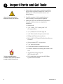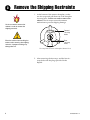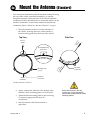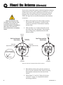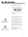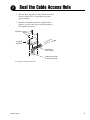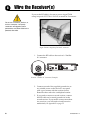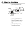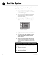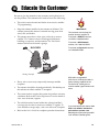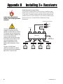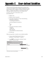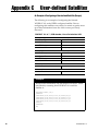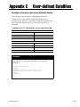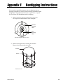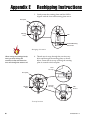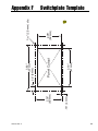
1
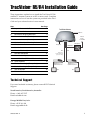
TracVision R5/R4 Installation Guide
®
These instructions explain how to install the TracVision R5/R4
satellite TV antenna system on an RV or motor coach. Complete
instructions on how to use the system are provided in the User’s
Guide and your selected receiver’s user manual.
Step
See Page
1.
Inspect Parts and Get Tools
2
2.
Plan the Installation
3
3.
Remove the Shipping Restraints
4
4a.
Mount the Antenna (Standard)
5
4b.
Mount the Antenna (Alternate)
6
5.
Cut the Switchplate Mounting Hole
7
6.
Wire the Antenna
8
7.
Seal the Cable Access Hole
9
8.
Wire the Receiver(s)
10
9.
Wire the Switchplate
11
10.
Mount the Switchplate
12
11a. Install Satellites (DISH 311 Receivers Only)
13
11b. Install Satellites
14
12.
Find the Skew Angle (Europe Only)
16
13.
Set the Skew Angle (Europe Only)
17
14.
Test the System
18
15.
Educate the Customer
19
TracVision Antenna
Radome
Vehicle
Power
11-16 VDC
Switchplate
Baseplate
Data/Power
RF2
(Optional North American
Systems Only)
Satellite Receiver 2
TV 2
RF1
Satellite Receiver 1
TV 1
Technical Support
If you need technical assistance, please contact KVH Technical
Support:
North America, South America, Australia:
Phone: +1 401 847-3327
Email: [email protected]
Europe, Middle East, Asia:
Phone: +45 45 160 180
Email: [email protected]
54-0359 Rev. A
1
1
Inspect Parts and Get Tools
1. Unpack the box and ensure it contains everything
shown on the supplied Contents List. Cables for the
R5/R4 system are stored beneath the antenna unit
during shipping.
Always lift the antenna by the
baseplate, never by the radome!
2. Carefully examine all of the supplied parts to
ensure nothing was damaged in shipment.
3. Gather all of the tools and materials listed below.
You will need these items to complete the
installation.
The Flash Update Wizard is
available to KVH-authorized dealers
through the KVH Partner Portal.
2
•
Electric drill
•
3/16" (5 mm), 5/32" (4 mm), and 3/32"
(2.5 mm) drill bits
•
3/4" (19 mm) hole saw and auger bit
•
9/64" allen wrench (European systems only)
•
Phillips and Flat head screwdrivers
•
RG-6 or RG-11 (75 ohms) RF cable (if installing two
RF cables)
•
Silicone sealant, RTV, or equivalent
•
7/16" open-end wrench
•
Construction adhesive suitable for the roof
•
Fasteners suitable for mounting the antenna to the
roof
•
Augat IT1000 crimp/strip tool
(KVH Part # 19-0242)
•
PC with the latest version of the KVH Flash
Update Wizard installed
54-0359 Rev. A
Plan the Installation
2
Before you begin, consider the following installation guidelines:
•
Minimize blockage. The antenna needs a clear view of
the sky to receive satellite TV. Using the table as a
guide, mount the antenna a suitable distance away
from obstructions on the roof, such as air
conditioners.
Block
ed!
Obstruction
A
Height of
Obstruction (A)
Minimum Distance
from Antenna (B)
8"
6"
10"
12"
12"
17"
14"
23"
16"
28"
Antenna
B
Vehicle Roof
Antenna Blockage
•
Find a location on a flat part of the roof on the
centerline of the vehicle.
•
The antenna must be mounted on a horizontal
surface. When placed flat on the mounting surface,
the mounting plates should be less than 7/16" above
the mounting surface.
7 "
16
Any gap larger than 7/16" will warp
the baseplate and seriously damage
the antenna.
Maximum Gap
Maximum Mounting Surface Slope
•
When choosing a location for the switchplate, find a
dry, flat location that will be easily accessible to the
user. Take into account cable lengths between
components, as well as accessibility to the equipment
after installation.
54-0359 Rev. A
3
3
Remove the Shipping Restraints
1. At the bottom of the antenna baseplate, cut the
two tie-wraps and pull them out of the baseplate
tie-wrap holes. You do not need to remove the
radome. The tie-wraps secure the antenna
mechanism to prevent shipping damage.
You do not need to remove the
radome in order to remove the
shipping restraints.
Forward
Tie-wrap
Holes
Exercise caution when handling the
antenna after removing the shipping
restraints. Improper handling may
damage the unit.
Rear
Tie-wrap
Holes
Tie-wrap Hole Locations on Baseplate (Bottom View)
2. After removing the tie-wraps, seal the four tiewrap holes with the plugs provided in the
kitpack.
4
54-0359 Rev. A
4a
Mount the Antenna (Standard)
You can mount the antenna with the baseplate connectors facing
the rear of the vehicle (standard orientation), or with the
baseplate connectors facing the front of the vehicle (alternate
orientation). Follow the steps below to mount the antenna in the
standard orientation. To mount the antenna in the alternate
orientation, skip to “Mount the Antenna (Alternate)” on page 6.
1. Place the antenna on the roof on the centerline of
the vehicle, ensuring the arrow on the antenna’s
front mounting plate faces the front of the vehicle.
Side View
Top View
Fr
o
Ve nt
hic of
le
Front of
Vehicle
Mounting Plate
(1 of 3)
Vehicle
Centerline
Ve
Ce hicl
nt e
er
lin
e
Forward Mounting
Plate Arrow
Baseplate
Connectors
Baseplate
Connectors
Standard Antenna Orientation
2. Apply construction adhesive to the bottom of the
antenna’s three mounting plates, across all holes.
3. Attach the three mounting plates to the roof using
15 fasteners appropriate for the roof’s
construction.
Due to the variation in RV roof
construction, consult with the RV
manufacturer to determine the safest
fastening method.
4. Seal all fasteners with silicone sealant or
equivalent.
54-0359 Rev. A
5
4b
Mount the Antenna (Alternate)
If you wish to mount the antenna with the baseplate connectors
facing the front of the vehicle (alternate orientation), you will
need to remove the radome, drill drain holes in the antenna
baseplate, then seal the existing factory-drilled drain holes.
Follow the steps below to mount the antenna in the alternate
orientation.
1. Remove the eight screws and washers securing
the radome to the baseplate. Carefully lift the
radome up until clear of the antenna assembly
and set aside.
(Alternate Orientation Only)
You MUST drill out the drain holes
as indicated to ensure that any
moisture that enters the baseplate is
able to drain. Ensure that the
factory-drilled holes are completely
sealed.
2. Drill out three 3/16" (5 mm) drain holes in the
rear-facing side of the baseplate. Then plug the
four existing factory-drilled drain holes with
silicone sealant.
Front of
Vehicle
Front of
Vehicle
Drill Out Alternate
Drain Holes
Baseplate
Connectors
Drain Hole
(Angle relative to front)
Seal Factory-drilled
Drain Holes
Drain Hole
(Angle relative to front)
Drain Hole Angles
(relative to baseplate)
Drain Hole
Vehicle
Centerline
Vehicle
Centerline
Alternate Antenna Orientation/Drain Hole Locations
3. Reinstall the radome, then place the antenna on
the roof on the centerline of the vehicle, ensuring
the baseplate connectors face the front of the
vehicle.
4. Follow Steps 2, 3, and 4 of “Mount the Antenna
(Standard)” on page 5 to complete the antenna
mounting procedure.
6
54-0359 Rev. A
5
Cut the Switchplate Mounting Hole
1. Find a dry, flat location inside the vehicle within
27 feet of the antenna to mount the switchplate.
The switchplate must be easily accessible to the
user.
2. Using the template supplied in Appendix F on
page 33, cut out the switchplate mounting hole in
the mounting surface.
3.82"
(97 mm)
.32" (8 mm)
2.36"
(60 mm)
.16" (4 mm)
Panel Cutout
3.19"
(81 mm)
Switchplate Cutout Dimensions
3/32"
A full-scale panel cutout template
has been provided for you in
Appendix F on page 33.
(2.5 mm) dia
2.05"
(52 mm)
Be sure to consider the 28-foot
length of the data/power cable when
choosing a location for switchplate. If
you require a longer cable, an
additional power supply MUST be
used. Failure to install an additional
power supply when a longer cable is
used can result in serious damage to
the antenna unit. KVH offers several
cable packages:
45' Cable with Power Supply
KVH Part # 72-0143-45
60' Cable with Power Supply
KVH Part # 72-0143-60
45' Cable without Power Supply
KVH Part # 32-0730-45
60' Cable without Power Supply
KVH Part # 32-0730-60
Power Supply
KVH Part # 19-0402
54-0359 Rev. A
7
6
Wire the Antenna
1. Drill a 3/4" hole in the roof for the cable access
hole. Smooth the edges of the hole to prevent
chafing of the cable.
2. Connect the antenna data/power cable to the
antenna’s center connector and lock in place.
RF2
(to 2nd Receiver)
North American
Systems only
Data/Power
(to Switchplate)
RF1
(to Receiver)
Antenna Baseplate Connectors
3. Connect one RF cable to the antenna’s “RF1”
connector. Hand-tighten first, then tighten with a
7/16" wrench for 1/4 turn.
4. Slide the rubber sealing boot up the RF cable until
it covers the connector. This boot will help protect
the connector from the elements.
Leave the protective cap installed on
the RF2 connector unless
connecting a second RF cable.
5. (North American Systems Only) - If you plan to
connect more than one receiver, connect a second
RF cable to the “RF2” connector, then slide the
rubber sealing boot up the RF cable.
6. Route the cables down through the cable access
hole in the roof. Be sure to maintain a service loop
(approximately 8") on the roof to allow plenty of
slack.
7. Route the data/power cable to the switchplate
location inside the vehicle.
(North American Systems Only)
If you need to connect three or more
receivers, refer to Appendix B on
page 22.
8
8. Route the RF1 cable to the receiver. If you
connected a second RF cable, route the RF2 cable
to the second receiver.
54-0359 Rev. A
7
Seal the Cable Access Hole
1. Seal the cable access hole with a liberal amount of
silicone sealant, RTV, or equivalent to protect
against leakage.
2. Install the clamshell ventilator, supplied in the
kitpack, over the cable access hole using three of
the supplied #6 screws.
#6 Screws
Clamshell
Ventilator
ion
Vis
c
a
r
To T nna
e
Ant
Data/Power
& RF Cables
Cable Access Hole
(in Roof of Vehicle)
Installing the Clamshell Ventilator
54-0359 Rev. A
9
8
Wire the Receiver(s)
If you cut the RF cable(s), be sure to use an Augat IT1000
crimp/strip tool (KVH Part # 19-0242) to attach an F-connector.
Do not use a screw-on, push-on, or
twist-on connector. Low quality
connectors will degrade system
performance and allow water/rain to
penetrate the cable.
Augat IT1000 Crimp/Strip Tool and F-connector
1. Connect the RF1 cable to the receiver’s “Satellite
In” connector.
TV ANT/CABLE IN
(NOT SATELLITE)
R
SATELLITE IN
DATA PORT
DIGITAL
AUDIO OUT
L
OUT TO TV
AUDIO
VIDEO
S-VIDEO
PHONE JACK
SATELLITE IN
Receiver “Satellite In” Connector (Example)
2. Connect one end of the supplied ground wire to
any suitable screw on the receiver’s rear panel
with a good contact with the receiver chassis.
Route the other end to the switchplate location.
3. If you need to connect a second receiver, connect
the RF2 cable and a second ground wire to the
second receiver. If you need to connect more than
two receivers, you will need to install an active
multiswitch; see Appendix B on page 22.
10
54-0359 Rev. A
9
Wire the Switchplate
The TracVision system requires an 11-16 VDC power input. A
quick-tripping circuit breaker should be installed between the
switchplate and vehicle power. Circuit overload protection
should be rated for 5 amps. If vehicle power fluctuates widely or
is noisy, a 12 VDC 5-amp AC/DC power supply should be
installed (KVH Part # 19-0402 or equivalent).
1. Disconnect vehicle power by removing the
appropriate vehicle fuse. Test the circuit to ensure
that no power is present.
2. Connect the antenna’s data/power cable to the
switchplate’s data/power connector and lock in
place.
Before wiring the switchplate, be
sure to disconnect vehicle power by
removing the appropriate vehicle
fuse. Test the circuit to ensure that
no power is present.
+12 VDC – Vehicle Power
Data/Power
Ground
Receiver Ground
Wire
Switchplate Connections
3. Connect the receiver ground wire(s) to the
switchplate’s ground terminal, as shown above.
4. Connect the switchplate to vehicle power and
ground, as shown above.
54-0359 Rev. A
11
10
Mount the Switchplate
1. Fit the switchplate flush into the switchplate
panel cutout that you made earlier.
C. Switchplate Cover
B. Switchplate
A. Panel Cutout
3.82"
(97 mm)
2.36"
(60 mm)
2.05"
(52 mm)
3/32"
(2.5 mm)
Screw Cavities
5/32" (4 mm)
3.19"
(81 mm)
Switchplate Mounting
2. Drill out four 5/32" (4 mm) holes in the screw
cavities in the switchplate.
3. Drill four 3/32" (2.5 mm) holes in the mounting
surface using the switchplate screw cavities as the
template. Then secure the switchplate assembly to
the mounting surface using four #6 self-cutting
screws.
4. Gently snap the switchplate cover onto the
switchplate.
5. Reconnect vehicle power. Be sure to replace the
vehicle fuse that you removed earlier.
12
54-0359 Rev. A
11a
Install Satellites (DISH 311 Receivers Only)
The following instructions explain how to install satellites for
DISH Network service for use with DISH 311 receivers only.
DISH Network does not currently support the use of any other
receivers for mobile customers. This procedure does not require a
PC. To install satellites for any other receiver model, proceed to
“Install Satellites” on page 14.
1. Turn on the TV and primary receiver (the receiver
connected to RF1).
Ensure that the vehicle is parked in a
blockage-free area. The antenna
must have a clear view of the sky to
receive satellite TV.
2. Set the switchplate’s POWER switch to the ON
(up) position. Wait one minute for system startup.
3. Using the receiver remote control, go to the “Point
Dish/Signal Strength” screen (press MENU,
6, 1, 1).
4. Choose “Check Switch” then press SELECT.
5. Choose “Test” then press SELECT to run the
Check Switch function. Wait 15 minutes for the
antenna to install and find both DISH satellites.
ON
OFF
TracVision Switchplate
6. Choose “Test” then press SELECT to run the
Check Switch function a second time.
7. Once the second Check Switch function is
complete, ensure the TV display appears exactly
as shown below:
Installed Switch: SW42
Input:
1
1
2
2
Satellite:
119
119
110
110
Polarity:
Odd
Even
Odd
Even
Status:
Satellite reception verified
If the TV display does not appear exactly as shown, run the
Check Switch function again.
8. Exit the menu and allow the receiver to download
the program guide.
9. The procedure is complete! Skip to “Test the
System” on page 18.
54-0359 Rev. A
13
11b
Install Satellites
The TracVision system is
preconfigured to track one of the
following satellite pairs:
Europe:
ASTRA1 (Sat. A)
HOTBIRD (Sat. B)
N. America
DIRECTV_101 (Sat. A)
DIRECTV_119 (Sat. B)
If your TracVision system is preconfigured to track your
desired satellite pair (see sidebar at left), skip to “Test the
System” on page 18. To select a different satellite pair, you will
need to connect a PC to the antenna and start the KVH Flash
Update Wizard. This procedure requires a PC with the Flash
Update Wizard installed. The Flash Update Wizard is available
to KVH-authorized dealers through the KVH Partner Portal.
Customers who wish to change the satellites that the TracVision
system tracks can visit any KVH-authorized dealer/distributor.
The new satellites can be configured in a just a few minutes.
1. Connect one end of the supplied PC data cable to
the DB9 maintenance port connector on the
switchplate. Connect the other end to the serial
port on your PC.
ON
OFF
Maintenance
Port
TracVision Switchplate
2. Double-click the KVH Flash Update Wizard
shortcut on your computer’s desktop to start the
Flash Update Wizard. You do not need to flash the
antenna; you will simply enter commands in the
“TracVision Antenna Comms” window.
Enter
Commands
Data
Display
If your computer does not have a
DB9 serial COM port, you can use
the following USB-to-RS232
adapter:
IOGear Part # GUC232A
(visit www.iogear.com)
14
TracVision Antenna Comms Window
3. Set the switchplate’s POWER switch to the ON
(up) position, then turn on the receiver(s). Wait
one minute for system startup.
54-0359 Rev. A
11b
Install Satellites ctd.
Follow the steps below to select which satellites to track. Enter all
commands in the “TracVision Antenna Comms” window.
4. Type HALT then press Enter.
5. Select any two satellite names from either the
North American or European satellite library.
Also, be sure you are located within your selected
satellite’s coverage area. Visit www.kvh.com/
footprint for satellite coverage maps. If your
desired satellites are not listed, you may also add any
two satellites of your choice. To add satellites to the
library, skip to Appendix C on page 23.
6. Type the following command (see the Key below)
then press Enter.
SATINSTALL,<sat_a_name>,<sat_b_name>
Key:
<sat_a_name> = the name of your choice
for Satellite A
<sat_b_name> = the name of your choice
for Satellite B (type NONE as the name
of satellite B if you wish to install only one
satellite)
NOTE: To receive DISH 500 service, install the
following two satellites: ECHO_119 & ECHO_110.
7. Type ZAP then press Enter to restart the antenna.
Wait one minute for the antenna to initialize.
Example:
To assign ASTRA2S and HOTBIRD for your satellite pair
(whereASTRA2S is designated as Satellite A and HOTBIRD is
designated as Satellite B):
Type HALT then press Enter.
Type SATINSTALL,ASTRAS2S,HOTBIRD then press Enter.
Type ZAP then press Enter.
Satellite Installation Names
Satellite
Install Name
North American Satellites†
DIRECTV 72.0° W
DSS_72
DIRECTV 101.0° W
DSS_101
DIRECTV 119.0° W
DSS_119
ECHOSTAR 61.5° W
ECHO_61
ECHOSTAR 110.0° W
ECHO_110
ECHOSTAR 119.0° W
ECHO_119
EXPRESSVU 82.0° W
EXPRESSVU
EXPRESSTV 91.0° W
EXPRESSTV
PAS9 58°W
PAS_9††
European Satellites
ARABSAT 26.0° E
ARABSAT
ASTRA1 19.2° E
ASTRA1
ASTRA2N 28.2° E
ASTRA2N
ASTRA2S 28.2° E
ASTRA2S
EUTELSAT W3A 7.0° E EUTEL_W3A
HISPASAT 30.0° W
HISPASAT
HOTBIRD 13.0° E
HOTBIRD
HOTBIRDWB 13.0° E
HOTBIRDWB
NILESAT 101 7.0° W
NILESAT
SIRIUS 5.0° E
SIRIUS
THOR 0.8° W
THOR
TURKSAT1C 42.0° E
TURKSAT1C
Other Satellite Designations
USER-DEFINED 1
USER1†††
USER-DEFINED 2
USER2†††
NONE
NONE
†
In N. America, you can also receive and
decode signals from the DIRECTV 110
satellite if a KVH HDTV converter
(KVH Part # 01-0260-05) is installed.
††
Be sure the receiver’s satellite configuration matches your
TracVision system’s settings. Your choice for Satellite A or B
must be the same satellite as Receiver Alternative 1 or 2,
respectively (or Receiver Alternative A or B, respectively), based
on your receiver, and must be assigned the Receiver DiSEqC 1 or
2 setting, respectively**. Refer to your selected receiver’s user
manual for details.
**DiSEqC settings apply only to European systems.
54-0359 Rev. A
Unlike other N. American satellites,
PAS9 service requires a linear
(European-style) LNB. Follow the
additional instructions for European
systems within this guide to install the
PAS9 satellite.
†††
USER1 and USER2 will only be
available if one or two user-defined
satellites have been added to the library
(see Appendix C on page 23).
15
12
Find the Skew Angle (Europe Only)
Approximate Latitude/Longitude
Grid #
Latitude Longitude
To optimize channel reception, you need to set the LNB skew
angle. Refer to your satellite service provider for the proper skew
angle for your specific satellite service and geographic location.
You can also find the skew angle for satellites in the TracVision
R5/R4 satellite library by entering your latitude and longitude
into the antenna. You can use the grid below to determine your
approximate latitude/longitude.
1
67°N
7°W
2
67°N
7°E
3
67°N
22°E
4
65°N
44°E
5
63°N
7°W
6
63°N
7°E
7
63°N
22°E
8
57°N
7°W
9
57°N
7°E
8
10
57°N
22°E
12
11
55°N
40°E
12
53°N
7°W
13
53°N
7°E
14
50°N
22°E
15
47°N
7°W
16
47°N
7°E
17
43°N
7°W
18
43°N
7°E
19
43°N
22°E
20
43°N
37°E
21
36°N
7°W
22
36°N
7°E
23
36°N
22°E
2. Type DEBUGON then press Enter.
24
36°N
37°E
3. Type the following command (see the Key below)
then press Enter.
2
1
5
3
6
4
7
9
10
13
14
11
16
15
17
21
19
18
22
23
20
24
To determine your approximate latitude/longitude, match the grid # above for
your location with the corresponding grid # at left.
Finding the Skew Angle for Satellites in the Satellite Library
1. Type HALT then press Enter.
GPS,XX,D,YYY,E
Key:
XX =
latitude (0-90)
D
S (South) or N (North)
=
YYY=
longitude (0-180)
E
E (East) or W (West)
=
4. Type SKEWANGLE then press Enter. The
TracVision system will respond with the skew
angle for the currently selected satellite.
16
54-0359 Rev. A
13
Set the Skew Angle (Europe Only)
1. Turn off the antenna and remove the appropriate
vehicle fuse to disconnect power. Ensure power is
removed from both the antenna and the
receiver(s) or multiswitch connected to RF1.
2. Remove the eight screws securing the radome.
Remove the radome and set it aside in a safe
place.
Radome
Before servicing the antenna unit,
turn off the antenna and disconnect
vessel power. Ensure power is
removed from both the antenna and
the receiver(s) or multiswitch
connected to RF1.
Screws
LNB
Rotating
Plate
Radome Screws
3. Using a 9/64" allen wrench, loosen the two LNB
bracket screws securing the LNB in the following
way: loosen one screw one full turn, then loosen
the second screw one full turn; repeat until the
LNB can be rotated freely.
IMPORTANT
Be sure to alternate the loosening or
tightening of the LNB bracket
screws. Turn one screw one full turn,
then turn the second screw one full
turn, until the operation is complete.
Failure to do so might cause unequal
pressure on the LNB and impair
signal reception.
LNB
-20˚ Skew
LNB Bracket
Screws
LNB/LNB Bracket Assembly
4. Rotate the LNB to align the skew arrow with the
skew angle that you determined earlier, then
tighten the screws (in the same manner that you
loosened them) until the LNB no longer rotates.
Then turn each of the two screws an additional
1/4 turn.
Negative
Skews
Positive
Skews
SKEW
Align the Skew Arrow with the Skew
Angle that You Determined Earlier
5. Reinstall the radome and restore vehicle power.
Be sure to replace the vehicle fuse that you
removed earlier.
54-0359 Rev. A
17
14
Test the System
Now all you need to do is turn the system on and ensure
everything works properly. Follow the steps below to test the
TracVision system.
1. Park the vehicle in a blockage-free area. The
antenna requires an unobstructed view of the sky
to receive satellite signals.
2. Turn on the receiver(s) and TV(s). For details on
operating the receiver, refer to your selected
receiver’s user manual.
3. Set the switchplate’s POWER switch to the ON
(up) position to turn on the TracVision system.
Wait one minute for the antenna to initialize.
ON
OFF
TracVision Switchplate
4. Within a few minutes, a picture should appear on
the TV.
5. (TracVision R5 Only) Take a road test and verify
that the antenna tracks the satellite while the
vehicle is moving.
6. When you have finished testing, shut down the
system. Be sure to leave the User’s Guide and the
Product Registration Form inside the vehicle for the
customer.
Refer to the User’s Guide for additional information
The User’s Guide contains detailed information on the
following:
18
•
Operational instructions
•
Troubleshooting information
•
DISH 500 configuration
54-0359 Rev. A
15
Educate the Customer
Be sure to give the manuals to the customer and explain how to
use the product. The customer also needs to know the following:
•
The receiver must be activated before it can receive satellite
TV programming.
•
Keep the radome installed on the antenna at all times. The
radome protects the antenna’s internal moving parts from
wind, rain, and debris.
•
The antenna must have a clear view of the sky to receive
satellite TV. Common causes of blockage include trees,
buildings, overpasses, and mountains. The TracVision
antenna will not work inside a garage.
BLOCKED!
IMPORTANT:
The customer must activate the
receiver to watch satellite TV.
To activate a DIRECTV receiver,
call KVH at 1-888-584-4163.
To activate a DISH Network
receiver, call 1-800-333-DISH.
To activate an ExpressVu receiver,
call 1-888-SKY-DISH.
Blockage Example
•
Heavy rain or snow may temporarily interrupt satellite
reception.
•
The antenna should be cleaned periodically. Dirt buildup on
the radome can affect satellite TV reception.
•
The owner needs to register the system for product warranty
validation. Refer to the Product Registration Form for details or
visit: www.kvh.com/register.
•
The vehicle must be located within the selected satellite’s
coverage area in order to receive its satellite TV signals. To
view satellite coverage maps, visit www.kvh.com/footprint.
•
Refer to the User’s Guide for complete operation instructions.
54-0359 Rev. A
KVH offers an upgrade kit
(KVH Part # 72-0218) that adds inmotion tracking capability to the
TracVision R4, allowing you to
receive satellite signals while on the
move.
If you need to paint the radome, use
ONLY non-metallic automotive
paint without a primer coat.
Metallic paint or paint having metallic
color will block satellite signals.
19
Appendix A
System Specifications
Physical Characteristics
Power
11-16 volts DC @ 2.5 amps
nominal, 3.5 amps peak
Dimensions/Weight
32" (81 cm) wide x 14.8" (38 cm)
high, 33 lbs (15 kg)
LNB
European system: Single output
N. American system: Dual output
Maintenance Port
EIA, RS232 @ 9600 bps,8,N,1
Pointing System
Elevation Range
10° to 70°
Azimuth Range
720°
Position Repeatability
0.1°
Environmental
Operating Temperature
-25°C to +55°C (-13°F to +131°F)
Storage Temperature
-40°C to +85°C (-40°F to +185°F)
Humidity
to 100 percent
54-0359 Rev. A
21
Appendix B
Instead of grounding individual
receivers, you can simply ground the
multiswitch.
Installing 3+ Receivers
(North American Systems Only)
If you need to connect three or four receivers, install an active
multiswitch (KVH Part # 19-0123, Channel Master model 6214IFD,
or equivalent). Install the multiswitch between the antenna unit
and the receivers as shown below. If you need to connect more
than four receivers, contact KVH for additional wiring
instructions.
TracVision RF Connectors
RF1
RF2
DC Power
The TracVision R5/R4 has the
capability of switching from one
satellite to another when you choose
TV channels that are carried by your
two selected satellites. However, the
use of an active multiswitch
interferes with communication from
the receivers to the antenna. In this
case, you will need to use the
optional TV/SAT Switch or the
optional HDTV Converter’s control
panel.
DC In
RHCP
+13V
VHF/UHF
LHCP
+18V
Multiswitch
Out 1
Receiver #1
Out 2
Receiver #2
Out 3
Receiver #3
Out 4
(Optional)
System Ground
Receiver #4
To order a TV/SAT Switch
(KVH Part # 01-0245) or a HDTV
Converter (KVH Part # 01-0260-05),
please call +1 401 847-3327.
22
54-0359 Rev. A
Appendix C
User-defined Satellites
The TracVision R5/R4 satellite library has two vacancies that
you may use to program two user-defined satellites, in case you
want to install/watch a satellite not already in the KVH satellite
library. To install a user satellite, you will need to obtain the
following satellite information from your satellite service
provider, or from sites on the Internet, such as
www.satcodx.com:
•
Satellite name
•
Satellite position (longitude)
•
Transponder information for each of the following
polarizations/frequencies:
– vertical high & vertical low
– horizontal high & horizontal low
or
– right
– left
•
Transponder information includes:
– frequency
– symbol rate
– FEC code, and
– network ID (in hexadecimal format)
•
Decoder type
Follow the steps below to install your user-defined satellite.
1. Connect with the Flash Update Wizard, as
described in “Install Satellites” on page 14.
2. Type HALT in the TracVision Antenna Comms
window, then press Enter.
Enter
Commands
Data
Display
TracVision Antenna Comms Window
54-0359 Rev. A
23
Appendix C
User-defined Satellites
3. Type the following command (see the Key below)
then press Enter.
SATCONFIG,USERX,YYY,Z,D,L
Key:
X
=
1 or 2 (This represents the first or second
user-defined satellite. Your TracVision
system allows up to two user-defined
satellites.)
YYY=
longitude (0-180)
Z
=
E (East) or W (West)
D
=
decoding type (1 = DSS-A,
2 = DSS-B, 3 = DVB)
L
=
LNB polarization (C = circular, L = linear)
The main board has now been configured to recognize the userdefined satellite. Next, you need to configure the RF board.
4. Type @DEGUGON then press Enter.
5. Type the following command (see the Key below)
then press Enter.
@SATCONFIG,X,N,F,S,C,ID,P,B,D
Key:
24
@SATCONFIG = directs data to the RF board
X
=
satellite location A or B
N
=
98 User-defined slot 1 (USER1)
99 User-defined slot 2 (USER2)
F
=
frequency in MHz (either 00000 or a
range from 10700 - 12700)
S
=
satellite transponder symbol rate in Mbit/
second (01000 - 29999)
C
=
FEC code
(e.g., 12, 23, 34, 56, 67, 78)
ID
=
satellite network ID in hexadecimal format
(0x####)
P
=
LNB polarization (V - vertical,
H = horizontal, R = right, L = left)
B
=
LNB down conversion frequency
(L = low, H = high, U = USA)
D
=
decoding type (1 = DSS-A,
2 = DSS-B, 3 = DVB)
54-0359 Rev. A
Appendix C
User-defined Satellites
Transponder information has to be entered for each of the
following polarizations/frequencies:
– vertical high & vertical low
– horizontal high & horizontal low
or
– right
– left
The TracVision R5/R4 antenna requires that the fields for all
transponder categories be filled in. If the selected satellite does
not have information for one or more of the transponder
categories, default information should be entered in the fields as
follows:
Transponder Data
Default Value
Frequency
00000
Symbol Rate
27500
FEC Code
the same value as provided for
those transponders with data
Network ID
0x0000
Polarity and Band
whichever combinations are not
already provided
6. Type @SAVE,A then press Enter to save your
settings (or @SAVE,B if data is for the User2
satellite).
7. Type @DEBUGOFF then press Enter.
8. Type ZAP then press Enter. Wait one minute for
the antenna to initialize.
One of your user-defined satellites has now been added to the
satellite library and is now available for tracking. To begin
tracking your user-defined satellite(s), refer to “Install Satellites”
on page 14, and choose “USER1” or “USER2” in Step 6.
54-0359 Rev. A
25
Appendix C
User-defined Satellites
An Example of Configuring a User-defined Satellite (Europe)
The following is an example of configuring the fictional
YOURSAT 101 as the USER1 configured satellite. Prior to
configuring this satellite or any others, be certain to get the most
up-to-date information from one of the sources previously
discussed.
YOURSAT 101 at 7°, DVB decoder, Linear Polarization LNB
Horizontal High
Frequency
11.966 GHz
Symbol Rate
27500
FEC Code
3/4
Network ID
2048 (dec) = 0x0800
Vertical High
Frequency
11.823 GHz
Symbol Rate
27500
FEC Code
3/4
Network ID
2048 (dec) = 0x0800
Vertical Low
No Data Listed
Horizontal Low
No Data Listed
Example:
Based on this information, the data entered via the PC would
look like this, assuming that YOURSAT 101 would be
Satellite A:
SATCONFIG,USER1,7,W,L
@DEBUGON
@SATCONFIG,A,98,11966,27500,34,0X0800,H,H,3
@SATCONFIG,A,98,11823,27500,34,0X0800,V,H,3
@SATCONFIG,A,98,00000,27500,34,0X0000,V,L,3
@SATCONFIG,A,98,00000,27500,34,0X0000,H,L,3
@SAVE,A
@DEBUGOFF
ZAP
26
54-0359 Rev. A
Appendix C
User-defined Satellites
An Example of Configuring a User-defined Satellite (N. America)
The following is an example of configuring the fictional
YOURSAT 101 as the USER1 configured satellite. Prior to
configuring this satellite or any others, be certain to get the most
up-to-date information from one of the sources previously
discussed.
YOURSAT 101 at 71°, DVB decoder, Circular Polarization LNB
Right
Frequency
11.966 GHz
Symbol Rate
27500
FEC Code
3/4
Network ID
2048 (dec) = 0x0800
Frequency
11.823 GHz
Symbol Rate
27500
FEC Code
3/4
Network ID
2048 (dec) = 0x0800
Left
Example:
Based on this information, the data entered via the PC would
look like this, assuming that YOURSAT 101 would be
Satellite A:
SATCONFIG,USER1,71,W,3,C
@DEBUGON
@SATCONFIG,A,98,11966,27500,34,0X0800,R,U,3
@SATCONFIG,A,98,11823,27500,34,0X0800,L,U,3
@SAVE,A
@DEBUGOFF
ZAP
54-0359 Rev. A
27
Appendix D
If you experience an operating
problem, refer to the
“Troubleshooting” section of the
User’s Guide. If you require technical
assistance, please contact your local
KVH-authorized dealer or distributor.
You can find an authorized technician
near you by visiting our website at
www.kvh.com/wheretogetservice. If
an authorized dealer/distributor is not
located nearby, contact KVH
Technical Support directly:
North America, South America,
Australia:
Phone: +1 401 847-3327
(Monday - Friday, 9:00 am - 6:00 pm,
Saturday, 9:00 am - 2:00 pm EST,
+5 GMT)
E-mail: [email protected]
Europe, Middle East, Asia:
Phone: +45 45 160 180
(Monday - Thursday, 8:00 am 4:30 pm, Friday 8:00 am - 2:00 pm,
-1 GMT)
E-mail: [email protected]
Replaceable Parts
The TracVision R5/R4 system has been designed with durability
and low maintenance in mind. If you experience an operating
problem or otherwise require technical assistance, contact your
local KVH-authorized dealer or distributor. If an authorized
dealer/distributor is not located nearby, contact KVH Technical
Support (see sidebar).
Replacement part numbers for units that can be serviced in the
field are listed below. These parts can be replaced by any KVHauthorized dealer/distributor.
Field Replaceable Units
Part Name
Part Number
Baseplate Assembly (TracVision R5)
02-1474-03*
02-1474-01**
Baseplate Assembly (TracVision R4)
02-1474-04*
02-1474-02**
Radome Assembly (TracVision R5)
02-0953-12†
Radome Assembly (TracVision R4)
02-0953-11†
Data/Power Cable
32-0730-28
RF Cable
32-0819-28
PC Cable
32-0628-06
Main PCB
72-0211
RF PCB
72-0212
Gyro (TracVision R5 Only)
72-0215
System Fuses
16-0017-3150
LNB (North American Systems)
72-0213
LNB (European Systems)
72-0214
Switchplate
02-1023-01
TV/SAT Switch (optional)
01-0245
*Baseplate assembly with dual-output circular LNB
(North American Systems)
**Baseplate assembly with single-output linear LNB
(European Systems)
†
Specify color when ordering
28
54-0359 Rev. A
Appendix E
Reshipping Instructions
If you need to repack the antenna unit for shipment, the two
shipping restraints (tie-wraps) removed during installation must
be replaced. The following instructions explain how to repack
the TracVision R5/R4 antenna unit for shipping.
1. Remove the four plugs from the forward and rear
tie-wrap holes on the bottom of the baseplate.
Forward
Tie-wrap
Holes
Rear
Tie-wrap
Holes
Antenna Baseplate (Bottom View)
2. Remove the eight screws securing the radome.
Remove the radome and set it aside.
Radome
Screws
Radome Screws
54-0359 Rev. A
29
Appendix E
Reshipping Instructions
3. Gently rotate the rotating plate until the LNB is
aligned with the forward mounting plate arrow.
Baseplate
Rotating
Plate
LNB
Forward Mounting
Plate Arrow
Reshipping Orientation
When moving the rotating plate by
hand, go slowly! Hitting the
mechanical stops with excessive
force will damage the antenna unit.
4. Thread one tie-wrap through the rear tie-wrap
holes and through the rotating plate, as shown
below. Fasten the tie-wrap, ensuring the rotating
plate is secured to the baseplate.
Rear
Tie-wrap
Baseplate
Forward
Tie-wrap
Rotating
Plate
LNB
Bracket
LNB
Tie-wrap Locations
30
54-0359 Rev. A
Appendix E
Reshipping Instructions
5. Thread a second tie-wrap through the forward
tie-wrap holes and over the LNB bracket. Fasten
the tie-wrap, ensuring the LNB bracket is secured
to the baseplate. Be sure to fasten the tie-wrap to the
LNB bracket, and not the LNB.
6. Reinstall the radome.
Ensure that the tie-wrap is fastened
to the LNB bracket, and not the LNB.
7. Place the entire antenna unit into its shipping box
using the original packaging material. Secure the
box to a pallet to ensure upright transport.
The repacking process is complete! The TracVision R5/R4 is now
ready for reshipment.
If you need to return the antenna, be
sure to obtain an RMA number from
KVH’s Technical Support
Department first. Be sure to write the
number clearly on the outside of the
box. Shipments received without an
RMA number will be returned to you
at your expense.
54-0359 Rev. A
31
54-0359 Rev. A
.16" (4 mm)
2.36"
(60 mm)
3.19"
(81 mm)
Panel Cutout
3.82"
(97 mm)
.32" (8 mm)
(2.5 mm) dia
2.05"
(52 mm)
3/32"
Appendix F
Switchplate Template
33