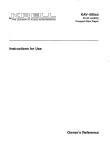
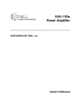
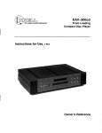
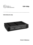
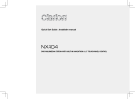
1
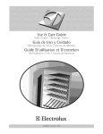
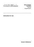
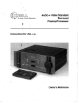
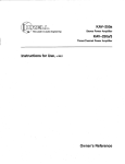
KAV-1500
Leaderin Audio Engineering
Five-ChannelPowerAmplifier
Instructions for Use
Owner’s Reference
KAV-1500
Five-ChannelPowerAmplifier
Instructions for Use
v 00.0
Krell Industries,Inc.
45 Connair Road
Orange, CT 06477-3650 USA
TEL 203-799-9954
FAX 203-891-2028
[email protected]
WEBSITE
http://www, krellonline.com
This product complieswith the EMC
directive (89/336/EEC)and the low-voltage directive (73/23/EEC).
WARNINGS
Theamplifier mustbe placedon a firm,/eve/surface whereit is not exposedto dt~ppingor splashing.
Theventilation grids on the top of the amplifier andthe spaceunderneath
the amplifier mustbe unobstructed
at all timesduring operation. Donot place flammable
material aboveor beneaththe amplifier.
Contactyour authorizedKrel/ dealer, distributor, or Krell beforeusingany devicesdesignedto alter or stabilize the ACpowerfor the KAV-1500.
Before connectingthe KAV-1500,
makesure the amplifier is turned off and any output device (such as
preamplifier) is in muteor stand-bymode.Makesure all cable terminationsare of the highest quality and
free fromfrayedends,short circuits, or cold solder joints.
Useonly oneset of inputs to the amplifier at a time.
After reconfiguringfor MAT,do not usemorethan one input at a time.
After bridging, one channelmust remainunbridged.
THEREARE NO USERSERVICEABLEPARTS INSIDE ANY KRELL PRODUCT.
Pleasecontactyour authorizedKrell dealer, distributor, or Krell if youhaveanyquestionsnot addressed
in
this referencemanual.
Thisproductis manufactured
in theUnitedStatesof Amedca.
Krell®is a registeredtrademark
of Krell Industries,Inc., andis restrictedfor useby Krell
TMis a trademark
Industries,Inc., its subsidiaries,andauthorized
agents.MultiAmp
Throughput
of Krell Industries,Inc. All othertrademarks
andtradenames
areregisteredto their respective
companies.
©2000byKrell Industries,Inc. All rights reserved
P/N 303961
Contents
Page
INTRODUCTION
1
DEFINITION OF TERMS
1
UNPACKING
3
PLACEMENT
4
AC Power Guidelines
4
FRONTPANEL DESCRIPTION: KAV-1500
6
BACK PANEL DESCRIPTION: KAV-1500
8
CONNECTINGTHE KAV-1500 AMPLIFIER
TO YOUR SYSTEM
10
Input and Output Connections
10
OPTIONAL SYSTEM CONFIGURATIONS
12
Multi AmpThroughput
12
Bridged Operation
16
Exampleof Connection Scenario: Multi PowerMode
18
AMPLIFIER OPERATION
19
On/Off and Operation
19
TROUBLESHOOTINGSYSTEM NOISE
19
QUESTIONS AND ANSWERS
20
WARRANTY
21
RETURN AUTHORIZATION PROCEDURE
22
SPECIFICATIONS
23
Krell KAV-1500
Amplifier
iii
Illustrations
iv
Page
FIGURE1 The KAV-1500Front Panel
5
FIGURE 2 The KAV-1500Back Panel
7
FIGURE 3 Reconfiguring the KAV-1500for MATOperation
13
FIGURE 4 Reconfiguring the KAV-1500for Bridged Operation
15
Krell KAV-1500
Amplifier
Introduction
Thankyou for your purchaseof.the Krell KAV-1500
Five-ChannelPowerAmplifier.
TheKAV-1500
amplifier providessubstantial five-channeloutput powerthat delivers
realistic musicreproductionat an exceptionalvalue. Theamplifier canbe customized
with a variety of optional systemconfigurations,including a multi powermode
usingthe
Multi AmpThroughput(MAT)feature, andbridged operation. TheKAV-1500
amplifier
hasbalancedandsingle-endedinputs for compatibility with other components.
The
multi-channel
(DB-25)input also allowsyouto integrate the amplifier easily and
seamlesslyinto hometheater or wholehousesystems.Theamplifier can be operated
usingthe 12 VDCpoweron/off (12 V trigger) signals from other components.
This referencemanualcontainsimportantinformationon placement,installation, and
operationof the KAV-1500
amplifier. Pleasereadthis informationcarefully. A thorough
understanding
of thesedetails helpsensuresatisfactoryoperationandlong life for your
KAV-1500
amplifier and related systemcomponents.
Definition of Terms
Followingare the definitions of keytermsusedin your owner’sreferencemanual.
CONNECTIONS
Bridging
A methodof linking two amplifier channelsby distributing the speakerload between
the
positive bindingposts. Bridgingthe channelsquadruplesthe powerrating at 8 Ohms.
Bridgedconfigurationsshouldnot be usedwith loads under4 Ohms.
Krell Multi AmpThroughput
(MAT)
Aninternal connection
option that sendsthe same
musicsignal to all amplifier channels
using onebalancedor single-endedconnection.MATreducesinstallation complexity
andcabling requirements
in systemscontainingmultiple amplifiers. MATalso allows a
variety of connectionscenarios,includingpoweringmultiple pairs of loudspeakers
to
extendthe listening environment
throughoutyour home.
INPUTS AND OUTPUTS
Balanced
A symmetrical
input or outputcircuit that hasequalimpedance
fromboth input terminals
to a common
groundreferencepoint. Theindustry standardfor professionalandsound
recordinginstallations, balancedconnectionshave6 dBmoregain than single-ended
connections
andallow the useofr long interconnectcables.
KrellKAV-1500
Amplifier
1
Definition
of Terms, continued
Single-ended
A two-wire input or output circuit, Usecare whenusing single-endedconnections,in
whichthe ground,connectionis madelast andbrokenfirst. Turn the systemoff prior to
makingor breaking single-ended connections. Single-endedconnections are not
recommended
for configurations requiring long cable runs.
Multi-channel (DB-25)
A balancedinput or output circuit that allows for the simultaneousconnectionof all
audio outputs plus one 5 VDC(5 Volt tdgger) via a single cable. DB-25inputs and
outputs are becomingpopular for connecting multi-channel ANprocessors and power
amplifiers, simplifying the integration of the two components
into your system.
OPERATION
Off
Whenthe powerbutton on the front panel is pressedand the blue powerLEDturns off,
the component
is off.
Operational Mode
Whenthe powerbutton on the front panel is pressedand the blue powerLED
illuminates, the component
is in the operational modeand ready to play music.
Stand-by Mode
A low powerconsumption
status that keepsthe audio andregulator circuits at idle. Krell
recommends
leaving the componentin the stand-by modewhenit is not playing music.
2
Krell KAV-1500
Amplifier
Unpacking
Openthe shipping box, which contains:
1 amplifier unit (packedin foamend-caps)
4 ribbon connection cables
Fuses
2 AGC-~ (~-amp) speaker fuse
1 slow-blow (20 ampfor 100/120Vor 12 ampfor 220/240V)line fuse
1 12 VDCoutput (12 V trigger) cable
1 T-15 Torx wrench
1 packet containing the owner’s reference manualand the warranty registration
card.
IMPORTANT
Twopeople are neededto removethe amplifier from the shipping box.
1. Onepersongrasps the undersideof the foamend-capsat one end of the amplifier;
at the sametime, the secondperson grasps the underside of the foamend caps at
the other endof the amplifier.
2. Slowlylift the amplifier straight out of the shippingbox.
3. Placethe amplifier in a safe location andremovethe protective plastic wrapping.
Notes
/f any of these items are not included in the shipping box, pleasecontact your
authorizedKrell dealer, distributor, or Kre// for assistance.
Saveall packingmaterials. If youship your amplifier in the future, repackthe unit in its
original packagingto prevent transit damage.See Return Authorization Procedure,
on page22, for moreinformation.
Krell KAV-1500
Amplifier
3
Placement
Before you integrate the KAV-1500
into your system,review the following guidelines to
choosethe location for the component.
This will facilitate a clean, trouble-free
installation.
The KAV-1500
requires at least two inches (5 cm) of clearance on each side and
least two inches (5 cm) of clearance abovethe componentto provide adequate
ventilation.
TheKAV-1500
doesnot require any type of special rack or cabinet for installation. For
the dimensionsof your amplifier see Specifications, on page23.
Place the amplifier as close to the loudspeakersas possible and keep the speaker
cable length to a minimum.Speakercable adds impedanceto the load the amplifier
mustdrive, regardlessof the cable’s gauge.Krell amplifiers drive the lowest
impedanceswith ease, but long speaker cables reduce the maximum
powerthat is
delivered to the loudspeakers.
AC POWERGUIDELINES
Krell recommends
operating each amplifier from a dedicated 15-ampACpowerline.
For maximum
power output, operate the KAV-1500amplifier from a dedicated 20-amp
ACpowerline.
4
Krell KAV-1500
Amplifier
FIGURE1
THE KAV-1500 FRONT PANEL
KAV-1500
1 PowerButton
2 Power LED
Front Panel Description: KAV-1500
See Figure 1 on page 5
1 Power Button
Usethis button to switch the KAV-1500
powerfrom off to the operational modeand
also to switch the 12 VDCoutput (12 V trigger) on andoff.
2 Power LED
Theblue powerLEDilluminates whenthe amplifier is in the operational mode,
6
Krell KAV-1500
Amplifier
FIGURE2
3
THE KAV-1500 BACKPANEL
8
9
INPUT---~
5
r-~
/
AGC-12
/
~
10
INPUT
/
6
11
7
12
KAV-1500
PowerAmplifier
~
AGC-12
AGC42
OUTPUT
(LIEF’I"SURROUNO)
20 23 19 14
19 15
21
OUTPUT
(LEF’r)
1916
Balanced
Inputs
3 Right Surround
Input
4 Left Surround
Input
5 CenterInput
6 RightInput
7 Left Input
Single-endedInputs
8 RightSurround
Input
9 Left Surround
Input
10 CenterInput
11RightInput
12Left Input
Multi-Channel
Input
13 Multi-channel
Input
1917
Amplifier ChannelOutputs
14 Right Surround
Output
15 Left Surround
Output
16 CenterOutput
17Right Output
18 Left Output
Fuses
19 AGC-~uses
"-,
20 Line Fuse
RemoteConnections
21 12 VDCRemote
PowerOut
22 12 VDCRemote
PowerIn
Power
23 ACPowerCord
1918
22
BackPanel Description: KAV-1500
SeeFigure 2 on page7
TheKAV-1500
backpanelprovidesconnectionsfor all inputs andoutputs, remote
connectioninput andoutput links, andACpowersupply.
Balanced Inputs
3, 4, 5, 6, 7 Inputs
These
arethe right surround
(3), left surround
(4), center(5), right (6), and
KAV-1500
channelinputs for output deviceswith balancedXLRconnectors.
Single-ended Inputs
8, 9, 10, 11, 12 Inputs
These
arethe right surround
(8), left surround
(9), center(10), right (11), andleft
KAV-1500
channelinputs for output deviceswith single-endedRCAconnectors.
SeeReconfiguring the KAV-1500for MAT,on page14, and Reconfiguring the
KAV-1500
for BridgedOperation,on page16, for information on optional system
configurations.
Multi-channel Input
13 Multi-channelInput
This is the DB-25input, for connectingto the DB-25output of a preamp/processor.
The
DB-25
input incorporatesall five channelsplus a 5 VDC(5 Volt trigger), andallowsyou
to sendall audiosignalsandturn the amplifieron andoff via a singlecable.
Amplifier Channel Outputs
14, 15, 16, 17, 18 Outputs
These
are the right surround
(14), left surround
(15), center(16), right (17), andleft
KAV-1500
amplifier channeloutputswith five-way loudspeakerbinding posts. The
loudspeaker
bindingpost terminalsacceptspadelugs, bare wire, bananaplugs, or
pins. Usethe red terminalfor the positive connection
andthe black terminalfor the
negativeconnection.
SeeInput andOutputConnections,on page 10, Connectingthe KAV-1500
Reconfigured
for MAT,on page14, and Connecting
the BridgedKAV-1500, on
page17, for moreinformationon amplifier channeloutput connections.
8
Krell KAV-1500
Amplifier
BackPanel Description, continued
Fuses
19 AGC-12 Fuses
TheAGC12 Volt loudspeakerfuses protect the KAV-1500
against short circuits in
loudspeakeroutput.
20 Line Fuse
Theline fuse protects the KAV-1500
against short circuits in internal powersupplies,
Note
Fusesmust be replaced with the fuse value specified on the KAV-1500back panel
Use a 20 ampslow-blow line fuse for 100/120V systemsor a 12 ampslow-blowline
fuse for 220/240V systems,
RemoteConnections
21 12 VDC Remote Power Out
The KAV-1500is equipped with an output that sends 12 VDCpoweron/off (12
trigger) signals to other Krell components
andother devicesthat incorporate a 12
trigger.
22 12 VDCRemote Power In
The KAV-1500is equippedwith an input that receives 12 VDCpoweron/off (12
trigger) signals from other Krell components
and other devicesthat incorporate a 12
trigger. This allows you to turn the KAV-1500
on andoff using a Krell or other
component
in a custominstallation.
Notes
12 VDCOut~In (12 V trigger) remotepoweris limited to 30 ma.
Consult the owner’s manualof eachcomponent
usedin a custominstallation to take full
advantageof the KAV-1500remotecapability.
Power
23 AC Power Cord
The KAV-1500is equipped with a hardwired ACpowercord,
Krell KAV-1500
Amplifier
Connectingthe KAV-1500Amplifier to Your System
INPUT AND OUTPUT CONNECTIONS
Followthesesteps to connectthe KAV-1500
amplifier to your system.
1. Makesure all powersourcesandcomponents
are off before connectinginputs and
outputs=
2. Neatlyorganizethe wiring betweenthe amplifier andall systemcomponents.
SeparateACwires from audio cables to prevent humor other unwanted
noise from
beingintroducedinto the system,
3. Connect
the interconnectcablesfromyour outputdeviceto the amplifier inputs. The
KAV-1500
is equipped
with balanced
(3, 4, 5, 6, 7) or single-ended
(8, 9, 10, 11,
inputs located on the backpanel. Thebalancedinputs usethree-pin XLR
connectors;the single-endedinputs use RCAconnectors.
or
Usethe multi-channel(DB-25)connectorto simplify the integration of the KAV-1500
into your system.
Connectthe DB-25output on your preamp/processor
to the DB-25input (13)
located on the back panel of the KAV-1500.
TheDB-25cable simultaneously
transmitsaudiooutputsandTrigger 1 signals from the Krell Home
TheaterStandard
SurroundPreamp/processor
(HTS)DB-25output to all inputs anda 5 VDC(5 Volt
trigger) on the KAV-1500
via the DB-25input.
Note
Youneedto configureTrigger 1 on the HTSbefore operation.
IMPORTANT
Donot connectthe multi-channelinput andsingle-endedor balancedinputs at the
sametime.
4. Connectthe loudspeakercables to the KAV-1500
amplifier channeloutput speaker
bindingposts(14, 15, 16, 17, 18)locatedon the backpanel.
Theamplifier channeloutputsfor the KAV-1500
usefive-way loudspeakerbinding
posts. Theloudspeaker
binding post terminals acceptspadelugs, bare wire, banana
plugs,or pins. Usethe red terminalfor the positive connection
andthe black
terminalfor the negativeconnection.
5. Plugthe endof the ACpowercord into the ACoutlet.
Theamplifier is nowreadyfor operation.SeeAmplifier Operation,on page19.
1o
Krell KAV-1500
Amplifier
TheKAV-1500
amplifier is shippedwith shorting pins in the XLRinputs. Thesepins
shouldremainin the XLRinputs if the amplifier is operatingin the single-ended
mode.
When
the shortingpin is insert,ed, pins1 (lowerleft) and3 (top) are shortedtogether.
Remove
the shortingpins to connectthe amplifier for balancedoperation.
TheXLRpin configurationis describedbelow:
Pin1
Ground
°)
Pin 2
Non-inverting
(0
°)
Pin 3
Inverting(180
Krell recommends
using balancedinterconnectcables. Balancedinterconnectcables
not only canminimizesonic loss but are also immune
to inducednoise, especiallywith
installations using long cables. Balanced
connectionshave6 dBmoregain than singleendedconnections.When
level matching
is critical, keepthis gain valuein mind.
Krell KAV-1500
Amplifier
11
Optional SystemConfigurations
The KAV-1500can be reconfigured for either Multi AmpThroughput(MAT)or bridged
operation.
IMPORTANT
Removing
the cover to reconfigure for MATor for bridged operation is the ONLY
instance you are authorized to removethe cover of ANYKrell component
without
voiding your Warranty.For moreinformation on product limitations and restrictions, see
Warranty, on page 21.
Before Reconfiguring for MATor Bridged Operation
Readthe following important safety instructions before you attempt to reconfigure your
amplifier for either MATor bridgedoperation:
1. Unplugthe powercord. Unplug the ACpower cord (23) from ACpower.
2. Avoidthe powersupply. After removingthe screws (see instructions below) and
the cover, locate andstay awareof the location of the powersupply (round, silver
structures behindthe amplifier front panel). Avoidmakingcontact with that area of
the amplifier.
3. Remove
jewelry. Rings, necklaces, bracelets, and other pieces of metal jewelry
can conduct an electrical charge. Consider removingthembefore attempting any
reconfiguration.
4. Alwaysreplacecover, Makesure the amplifier’s cover is properly replaced and
securedby all 14 cover screwsbefore resumingoperation.
IMPORTANT
Operatingthe amplifier without the cover properly replaced and securedmay
void your warranty.
MULTI AMP THROUGHPUT
Multi AmpThroughput(MAT)is an internal connection option for the KAV-1500
that
lets you sendthe samemusicsignal to all amplifier channelsusing one balancedor
single-endedconnection. MATreducesinstallation complexity and cabling requirements
in systemscontaining multiple amplifiers.
12
Krell KAV-1500
Amplifier
FIGURE3
RECONFIGURINGTHE KAV-1500 FOR MAT OPERATI()N
PC Input
Left
ToSlow
Start
Channel
8oard
J1M
Board showing
MAT jumper
For
Bridging
configuration
J
J6fl J4N ,,,J5 J7111 J12,, J11,llJ1,II
J13,1, J1811 Jr6111 CRj17 I~L~piiTB~5/~ES J~i ’ng J19~ ~J23 ~:0~i~2~
PRC- Permanent ribbon connections
MAT- Multi
For~,~eff. SurroundJ For~
(Do Not Remove)
Amp Throughput (MAT) ribbon connections
Right
Surround
I]J29IIIJ25
Reconfiguring the KAV-1500for MAT
See Figure 3 on page 13
Tools needed:T-15 Torx wrenchand four ribbon connection cables
1. Turn the KAV-1500
off by pressing the powerbutton (1) on the front panel. Theblue
powerLED(2) extinguishes. Unplugthe ACpowercord (23) from ACpower.
2. Using the T-15 Torx wrench,removethe 14 screwsthat secure the amplifier cover.
Carefully removethe cover.
3. Locatethe PCinput boardand jumperpins at the rear of the amplifier.
IMPORTANT
Do not removeor changethe ribbon connection cables already in place. These
connectionsare polarized to ensurethe correct phase.
4. Connectone end of the first ribbon connectioncable to jumperpin J5. Connectthe
other end of the ribbon connectioncable to jumperpin J11.
5. Usethe remaining ribbon connection cables to connect:
J10 to J16
J 17 to J22
J23 to J28
6. Replacethe cover, sliding the front panel endin first and, using the T-15Torx
wrench,secure all 14 cover screws.
The KAV-1500amplifier is nowreconfigured for MAToperation.
Connecting the KAV-1500Reconfigured for MAT
See Figure 2 on page 7
1. Connectyour output device to oneof the balancedinputs (3, 4, 5, 6, or 7) or one
the single-endedinputs (8, 9, 10, 11, or 12) on the KAV-1500
back panel.
IMPORTANT
Do not use the multi-channel input if you have reconfigured the KAV-1500for MATor
bridged operation.
2. Connecteachamplifier channeloutput (14, 15, 16, 17, 18) to a separate
loudspeaker,using the positive and negative terminals on the speakerbinding posts.
14
Krell KAV-1500
Amplifier
FIGURE4
RECONFIGURING
THE KAV-1500 FOR BRIDGEDOPERATI( )N
Do not attempt to bridge channels in any wayother than specified below.
Option 4
i
OptI
Left
ToSlow
Channel Stad
m
Board
Opti°n
Right For
Channel
Bridging
J,~ J12fl
Option 1: Bridging
the Left and
Right Channels
,~
Opt~
!
For
Bridging
Bri~
J5
/ J6111J411II
2
CenterFor
Channel
Bridging
For
LeftSurroundFor
KRELLINDUSTRIES
Bridging
RDJ24N
J11~11(~],13~J18H J16fl H J17 1"%7BOA05B
r----BRG
(~l~;~e,
Option 3: Bridging
I-~-BRG
the Center and Left ~....-L....~..~
Surround Channels f
-~
Bri~ing~
J7111
J1211
J11111
1418111J1611II317 P10705B J2411
J19111J2211
111423
I
~__~---PRC
~__~-- PRC
Option 2: Bridging
the Right and
Center Channels
I
For
/ J12111
Option 4: Bridging
I---BRG
the Left Surroundand
~
Right Surround Channels /
r----BRG
~
/
f
Right
~
..... =..X
J1111J1ql
J13111
J1811
J1611
IIIJ17
/
For
~
|
~ Left
For~
Bridgin~"~Su~und
n n Bd~]ing
n~
324111 31911132211
ii323 3301132811
iii329
~__~-PRC
PRC-- Permanentribbon connections (Do Not Remove)
~
BRG-- Bridging
BRIDGED OPERATION
TheKAV-1500
canbe reconfiguredto bridge four of its amplifier channelsto operate
as two combined
amplifier channels.Thebridgedamplifier channelseachdeliver 1,100
Wattsinto an 8 Ohmload. Theunbridgedamplifier channelcan be connectedto a
separateloudspeaker.
IMPORTANT
Onechannelmustremainunbridged.
Reconfiguring the KAV-1500 for Bridged Operation
See Figure4 on page15
Tools needed:T-15 Torx wrenchandtwo ribbon connectioncables
1. Turnthe KAV-1500
off by pressingthe powerbutton (1) on the front panel. Theblue
powerLED(2) extinguishes. Unplugthe ACpowercord (23) from ACpower.
2. Usingthe T-15Torx wrench,removeall 14 coverscrewsthat securethe amplifier
cover. Carefully remove
the cover.
3. Locatethe PCinput boardandjumperpins at the rear of the amplifier.
4. Followthe directions below.Youmaybridge channelsusing:
Options1 and3 or Options1 and4 or Options2 and4
IMPORTANT
Donot attemptto bridgechannelsin anywayother than specifiedin thesedirections.
Option1: To bridgethe left andright channels,connectoneendof the ribbon
connectioncable to jumperpin J6. Connectthe other endof the ribbon connection
cableto jumperpin J11.
Option2: To bridge the right andcenter channels,connectoneendof the ribbon
connectioncableto jumperpin J12. Connectthe other endof the ribbon connection
cableto jumperpin J17.
Option3: To bridge the centerandleft surroundchannels,connectoneendof the
ribbon connectioncable to jumperpin J18. Connectthe other endof the ribbon
connectioncableto jumperpin J23.
Option4: To bridge the left surroundandright surround
channels,connectone
endof the ribbon connectioncable to jumperpin J24. Connect
the other endof the
ribbon connectioncable to jumperpin J29.
5. Replacethe coverand, using the T-15Torx wrench,secureall 14 coverscrews.
TheKAV-1500
amplifier is nowreadyfor bridgedoperation.
16
Krell KAV-1500
Amplifier
Connectingthe Bridged KAV-1500
See Figure 2 on page 7
Connectthe bridged channelsas follows:
Option1
1. Whenthe left and right channelsare bridged, connectthe output cable from the
output deviceto the appropriatebalanced(7) or single-ended(12) left channelinput.
2. Connectthe positive loudspeakerlead (red) to the positive binding post on the left
amplifier channel(18), Connectthe negative loudspeakerlead (black) to the positive
bindingpost of the right amplifier channel(17).
Option 2
1. Whenthe right and center channelsare bridged, connect the output cable from the
output device to the appropriatebalanced(6) or single-ended(1 1) right channel
output.
2. Connectthe positive loudspeakerlead (red) to the positive binding post on the right
amplifier channel(17). Connectthe negative loudspeakerlead (black) to the positive
binding post of the center amplifier channel(16).
Option 3
1. Whenthe center and left surround channelsare bridged, connectthe output cable
from the output device to the appropriate balanced(5) or single-ended(10) center
channelinput.
2. Connectthe positive loudspeakerlead (red) to the positive binding post on the center
amplifier channel(16). Connectthe negative loudspeakerlead (black) to the positive
bindingpost of the left surroundamplifier channel(15).
Option 4
1. Whenthe left surround and right surroundchannelsare bridged, connectthe output
cable from the output device to the appropriatebalanced(4) or single-ended(9)
surroundchannelinput.
2. Connectthe positive loudspeakerlead (red) to the positive binding post on the left
surroundamplifier channel(15). Connectthe negative loudspeakerlead (black)
the positive binding post of the right surroundamplifier channel(14).
For each option, the remaining unbridged channel maybe connectedto a separate
loudspeakerfor normaloperation.
IMPORTANT
Whenoperating the amplifier in bridged modeand using an output device with a
single-ended RCAcable, be sure to removethe shorting pin from the balancedXLR
input.
Krell KAV-1500
Amplifier
17
Multi Power Mode Connection
Multi powermode
is onepossibleconnection
scenariousingthe KAV-1500’s
Multi Amp
Throughput
(MAT)feature. WithMulti PowerMode,youcanusethe KAV-1500
reconfiguredfor MAT
to independently
power
multiplepairsof stereoloudspeakers,
to extendthe
listeningenvironment
throughout
yourhome.When
the KAV-1500
is reconfigured
for MAT,
eachchannelpowers
an individualloudspeaker,
withoneKAV-1500
dedicated
to driving
outputs
to the left loudspeakers
andoneKAV-1500
drivingoutputs
to the right loudspeakers.
Thediagram
below
illustratesthis connection
scenario:
Left Speakers
Living
Room
(L)
Kitchen
(L)
Patio(L)
+
Gym(L)
Bedroom
(L)
-
LeftAmplifier
RightAmplifier
Bedroom
(R)
RightSpeakers
18
Krell KAV-1500
Amplifier
Amplifier Operation
ON/OFF AND OPERATION
Whenpoweringup your system,turn amplifiers on last. Whenpoweringdownyour
system,turn amplifiersoff first. Theprocedures
for amplifier operationfollow.
front panel. Theblue powerLED(2)
1. Pressthe powerbutton (1) on the KAV-1500
illuminatesandyouheara click. Theamplifier is nowreadyfor operation.
2. Withthe outputdevicemutedor volumecontrol fully lowered,select an output
device.Decrease
or increasethe volume
control to the desiredlistening level.
3. Beforeturning the systemoff, muteor lower the output devicevolume.Pressthe
front panelpowerbutton(1) to turn the amplifieroff. It is nowsafeto turn off the rest
of the system.
IMPORTANT
Alwaystumoff the amplifier beforechanginginput connections,andmuteor fully
attenuatethe preamplifier/eve/when
switching sources.
TheKAV-1500has tremendous
reservesof powerandsafely drives loudspeakersto
extremelyhigh soundpressurelevels. However,
use care whensetting high playback
levels andlowerthe volume
level at anysign of loudspeaker
distress.
Troubleshooting System Noise
Whenyou mix and matchhigh-performance
audio components,eachwith its own
groundpotential, a low frequencyhummayoccurin oneor all loudspeakers.
If this
happenswhenyou place the KAV-1500
into your system,follow these simple
troubleshootingsteps.
1. Checkthat all input andoutputconnections
are of soundconstruction.
2. Withthe amplifier off, remove
the interconnectcables,thenturn the amplifier on.
If the humdisappears,
turn the amplifier off andreinsert oneof the interconnect
cables.Turnthe amplifier backon. Repeatthis processfor eachcable.
with oneor both interconnectcablesreinserted, the cable
3. If the humreappears
needsto be replaced.
4. If the interconnectcablesare sound,youmaybe experiencinga groundloop.
PleasecontactyourauthorizedKrell dealer,distributor, or Krell for suggestions
on
howto eliminateit.
Krell KAV-1500Amplifier
19
Questions and Answers
Q. ShouldI leave the KAV-1500
amplifier on at all times?
A. No. Theamplifier doesnot havea stand-by mode.Leavingit on at all times would
result in considerableheat output and powerconsumption.For best results, turn the
amplifier off whennot in use, andallow a five minutewarm-up
after it is switchedto the
operational mode. See Amplifier Operation, on page 19.
Q. WhenI turn the amplifier on there is a loud humthrough the loudspeakers.What
should I do?
A. Whena new componentis introduced, a low frequency hummayoccur in one or
both loudspeakers.Checkthat all input and output connectionsand cables are of sound
construction. See Troubleshooting
SystemNoise, on page19. If the connections and
cables are sound, you maybe experiencing a ground loop. This can often be easily
eliminated. Pleasecontact your authorizedKrell dealer, distributor, or Krell for
suggestions.
Q. When
I connectthe amplifier to mysystemusing the single-endedinputs, a loud
buzz comesfrom myloudspeakers. Whatis it?
A. Checkthat the shorting pins for the KAV-1500
are inserted into the XLRinputs (the
unit is shippedwith the pins in place). When
using the single-endedinputs, these
shorting pins mustbe inserted betweenpins 1 and 3 to keep external noise from
corrupting the signal. For more information, see Connectingthe KAV-1500Amplifier
to Your System, on page 10.
Q. CanI bridge all the channels on my KAV-1500?
A. The KAV-1500has five channels. You can bridge four of those channels to operate
as two channels. Onechannel must remain unbridged. See Bridged Operation, on
page 16.
Q. I want to bridge the channelson myKAV-1500
but whenI openthe amplifier, there
are ribbon connectioncables already in place. ShouldI removethem?
A. No. Youramplifier is shippedwith ribbon connectioncables in place andpolarized to
ensure the correct phase(see Figure 3, on page13). Do not removeor changethese
ribbon connection cables. The KAV-1500
is not reconfigured for bridged or Multi Amp
Throughput(MAT)operation whenit is shippedto you. Usethe additional ribbon
connectioncables shippedwith the amplifier and instructions on pages12 and 16 to
reconfigure the KAV-1500for bridged or MAToperation.
20
Krell KAV-1500
Amplifier
Warranty
ThisKrell producthasa limitedwarranty
=of five yearsfor
partsandlaboroncircuitry. Should
this product
fail to performat anytimedudng
thewarranty,
Krell will repairit at no
costto theowner,
except
as set forth in this warranty.
Thewarrantydoesnot applyto damage
causedby acts of
Godor nature.
Thewarranty
onthis pageshall bein lieu of anyotherwarranty,expressed
or implied,including,butnotlimitedto, any
impliedwarranty
of merchantability
or fitnessfor a particular
purpose.Thereare no warranties whichexceedbeyond
thosedescribed
in this document.
If this productdoesnot
performas warranted
herein,the owner’ssole remedy
shall
berepair.In noeventwill Krellbeliable for incidental
or consequentialdamages
arising frompurchase,
use,or inability
to usethis product,evenif Krell hasbeenadvisedof the
possibility of suchdamages.
Proofof purchase
in theformof a bill of saleor receipted
invoicesubstantiating
that the unit is within the warranty
periodmustbepresentedto obtain warrantyservice. The
warranty
beginsonthe dateof retail purchase,
as notedon
thebill of saleor receipted
invoicefromanauthorized
Krell
dealeror distributor.
Thewarranty
for Krell products
is valid onlyin thecountryto
whichtheywereoriginally shipped,throughthe authorized
Krell distributorfor that country,andat thefactory.There
maybe restrictions on or changesto Krell’s warranty
because
of regulationswithin a specific country.Please
checkwith yourdistributor for a complete
understanding
of
thewarranty
in yourcountry.
If a unit is serviced
by a distributorwhodid not importthe
unit, theRmaybea chargefor service,evenif the product
is withinthewarranty
period.
FRightto thefactoryis yourresponsibility.Return
freight
withinthe UnitedStates(U.S.A.)is included
in the warranty.
If youhavepurchased
yourKrell productoutsidethe U.S.A.
andwishto haveit serviced
at the factory,all freight and
associated
charges
to the factory are yourresponsibility.
Krell will payretumfright to the U.S.A.-based
fright forwarderof yourchoice.Freightandothercharges
to shipthe
unit fromthe freight forwarder
to youare alsoyourresponsibility.
Krell is notresponsible
for anydamage
incurredin transit.
Krell will file claimsfor damages
asnecessary
for unitsdamagedin transit to thefactory.Youareresponsible
for filing
claimsfor shippingdamages
duringthe retumshipment.
Krell doesnot supplyreplacement
parts and/orproductsto
the ownerof the unit. Replacement
parts and/orproducts
will befurnished
onlyto thedistributorperforming
serviceon
this unit on anexchange
basisonly; anypartsand/orproducts returnedto Krell for exchange
become
the propertyof
Krell.
Noexpressed
or implied warrantyis madefor anyKrell
productdamaged
by accident, abuse,misuse,natural or
personal
disaster,or unauthorized
modification.
Anyunauthorizedvoltage conversion,disassembly,
component
replacement, perforation of chassis,
updates,or modifications performedto the unit will
voidthe warranty.
Theoperating
voltageof this unit is determined
by the factory andcanonlybechanged
by anauthorized
Krell distributor or at thefactory. Thevoltagefor this productin the
U.S.A.cannotbechanged
until six months
fromthe original
purchase
date.
In theeventthat Krell receivesa productfor warranty
service that hasbeenmodifiedin anywaywithoutKrell authorization,all warranties
onthat product
will bevoid.Theproductwill bereturned
to odginal
factorylayoutspecifications
at
the owner’sexpense
before it is repaired. All repairs
requiredafter theproducthasbeenreturned
to originalfactory specifications
will becharged
to thecustomer,
at current partsandlaborrates.
All operationalfeatures,functions,andspecifications
and
policiesare subjectto change
withoutnotification.
To register your product for warranty benefits,
complete
and return
the Warranty
Registration Card enclosed in the shipping
box within 15 days of purchase. Thankyou.
Krell KAV-1500
Amplifier
21
ReturnAuthorization
Procedure
To return this productto Krell, please
follow this procedure so that we may
serve you better:
1. Obtain a Return Authorization Number
(R/A number) and shipping address
from the Krell Service Department.
If you believe there is a problemwith your
component,
pleasecontact your dealer, distributor, or the Krell factory to discussthe
problembefore you return the component
for 2. Insureandacceptall liability for loss of
repair. To expediteservice, you maywish to
or damage
to this product during shipcomplete and e-mail the Service Request
mentto the Krell factory andprepayall
Formin the Service Section of our website
shipping charges. Please see the
at:
Warrantypagein this manual,concerning liability
for shipping damageand
http://www.krellonline.com
shipping charges.
To contact the Krell Service De3artment
TEL
FAX
E-MAIL
203-799-9954
Monday-Friday
9:00 AMto 5:00 PMEST
203-799-9796
[email protected]
This product mayalso be handdelivered if
arrangementswith the Service Department
have beenmadein advance.Proof of purchasewill be required for warrantyvalidation at the time of handdelivery.
IMPORTANT
Use the original packagingto ensuresafe
WEBSlTE http’J/www.krellonline.com
transit of this productto the dealer,distributor, or facto~ Kre// may,at its discretion,
KAV-1500
return this productin newpackaging
andbill
PRODUCT
NAME
SERIALNUMBER
the ownerfor such packagingif the product
received by Krell was boxedin non-standard packagingor if the original packaging
was so damagedthat it was unusable. If
Krel/ determines that new packaging is
required, the ownerwill be notified before
this productis returned.
To purchaseadditional packaging, please
contactyour authorizedKrell dealer, distributor, or the Krell ServiceDepartment.
22
Krell KAV-1500
Amplifier
Specifications
KAV-1500Five-ChannelAmplifier
FREQUENCY RESPONSE
20 Hz to 20 kHz +0 dB, -0.2 dB
0.4 Hz to 112 kHz +0 dB, -3 dB
SIGNAL TO NOISE RATIO
"A" WEIGHTED
118dB
TOTAL HARMONICDISTORTION (THD)
1 kHz < 0.06%
20 kHz < 0.25%
GAIN
26.4 dB
INPUT IMPEDANCE
100 kOhms
INPUT SENSITIVITY
2.15 Vrms
OUTPUT VOLTAGE
Peak to Peak
RMS
166 V
59 V
OUTPUT POWER, EACH CHANNEL
8 Ohms
300 W
DRIVEN
4 Ohms
600 W
BRIDGED
8 Ohms
1,100 W
POWER CONSUMPTION
Idle
Max.
INPUTS
280 W
3,460 W
5 single-ended via RCAconnectors
5 balanced via XLRconnectors
5 via DB-25connector
OUTPUTS
5 amplifier channelsvia five-way speaker
binding posts
DIMENSIONS
19wx 6.3h x 20.25din.
48.3w x 16h x 51.4d cm
WEIGHT
Shipping
125 lb., 56.81kg
Unit only
108 lb., 49.09kg
All operationalfeatures, functions, specifications,
and policies are subject to changewithout notification.
Krell KAV-1500
Amplifier
23
Krell Industries,Inc.
45 Connair Road
Orange, CT 06477-3650USA
TEL 203-799-9954
FAX203-891-2028
E-MAIL
[email protected]
WEBSITE
http://www, krellonline.com
KAV-1500
Five-Channel
PowerAmplifier
v 00.0