1
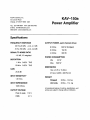
The Leaderin Audio Engineering
KAV-150a
Power Amplifier
Instructions for Use,v 98.0
Owner’s Reference
Contents
KAV-150a
PowerAmplifier
Page
INTRODUCTION
UNPACKING
PLACEMENT
4
Cabinetry Considerations
ACPowerGuidelines
Krell®Industries,Inc.
45 Connair Road
CONNECTINGTHE KAV-150a
TO YOUR SYSTEM
Orange, CT 06477-3650 USA
AMPLIFIER OPERATION
5
6
6
On/Off and Stand-by Operation
SystemNoise Considerations
E-MAILkrell@ krellonline.com
WEBSITE www.krellonline.com
5
Input and Output Connections
Configuring the KAV-150a
for BridgedOperation
TEL 203-799-9954
FAX 203-799-9796
4
6
7
WARRANTY
8
RETURNAUTHORIZATION
PROCEDURE
9
SPECIFICATIONS
®Industries,Inc. All rights reserved
©1998byKRELL
Back Cover
P/NI960101900088
CE Marking
This product complies with the EMCdirective (89/336/EEC) and the low-voltage
directive (73/23/EEC).
Introduction
The KAV-150ais backed by a comprehensive customersatisfaction policy and one
of the mostadvancedservice facilities in
the industry. For detailed information on
the terms and conditions of service, please
consult your warranty registration card, or
®.
contact your dealer, distributor, or Krell
®
Thankyou for your purchaseof the Krell
Unpacking
KAV-150a Power Amplifier.
The name
Krell ® has always represented components 1. Openthe box and removethe top layer of
that are the premier performers in their
foam.Youwill seethese items:
product categories. The KAV-150apower
1 KAV-150a
amplifier continuesin this Krell® tradition
1 AC power cord
2 spare speaker fuses
The KAV-150ais a stereo amplifier that
1 packet containing an introductory
maybe bridged into monauraloperation.
letter from DanD’Agostino,C.E.O.,
Designed as a compact component with
the Owner’sReferenceand the
exceptional sound, the KAV-150amaybe
WarrantyRegistration Card
interfaced easily into multi-amplifier sysNote
temsusing the 12 V trigger andthe bridging capability. The KAV-150auses proven ff anyof theseitemsare not included,please
Krell®circuits built with the samehigh qual- contactyour authorizedKrel/~ dea/eror distributor immediate/y
for assistance.
ity resistors, output devices, andinternal
electrical componentsused in all other 2. Carefully removethe unit and accesKrell®products. Frominput to output, the
sories from the box. Remove
the protecKAV-150auses discrete, fully complementive plastic wrapfromthe unit.
tary circuitry. All circuits up to the driver Note
stage operate in pure Class A. The
Saveall packingmaterials, ff you must
KAV-150a employs a wide bandwidth
ship your KAV-150ain the future, repack
designwith a very low negativefeedbackfor
the unit in its original packaging
to prevent
sonic accuracy throughout the frequency
transit damage.
spectrum.
This owner’s reference manual contains
important information on the placement,
installation, andoperationsof the KAV-150a.
Please read this information carefully. A
thorough understanding of these details
will help insure satisfactory operationanda
long life for the KAV-150a
and related system components.
KRELL® KAV-150a
THERE ARE NO USER-SERVICEABLE
PARTSINSIDE ANY KRELL® PRODUCT
Pleasecontact your authorizeddealer,
distributor, or KrelP, if you haveany
questionsnot addressedin this reference manual.
English Page3 of 12
Placement
WARNING
Theamplifier mustnot be located whereit
could be exposedto dripping or splashing
fluids.
Before you install the KAV-150a
into your
system,review the following guidelines to
choosethe location for the KAV-150a.
This
will facilitate a clean,trouble-free
installation.
TheKAV-150a
does not require any type of
specialrackor cabinetfor installation. Forthe
dimensions of the KA V- 150a, see
Specificationson page10.
Placethe KAV-150a
amplifier on a firm level
surfaceawayfromdirt or moisture. Ideally,
the amplifier should be placed as close to
the speakers as possible. Runlong balancedinterconnect cables to the amplifier
andkeepthe speakercable length to a minimum. Speaker cable adds impedanceto
the load the amplifier mustdrive, regardless
of the cable’sgauge.All KrelPamplifierswill
drive the lowest impedances
with ease, but
when impedance is added due to long
cable lengths, amplifier poweris wastedin
the cable. Longspeakercables reducethe
maximumpower that can be delivered to
the speakers.
Page4 of 12 English
CABINETRY CONSIDERATIONS
The KAV-150aamplifier can becomequite
warmunder normal operation. Install the
KAV-150a
in a location that provides unobstructedventilation.
IMPORTANT
Theventilation grids on top of the KAV- 150a
needto be unobstructedat all times during
operation. Do not place flammablematerial
on top of or beneath the KAV-150a.For
installation inside cabinet~extra ventilation may be necessary. Make sure the
KAV-150ahas adequate air circulation.
Generally two inches of clearance on each
side of the amplifier and eight inches of
clearance abovethe amplifier will provide
adequate ventilation.
In more extreme
instances, small fans can aid in removing
excess heat from internal spaces. Contact
your dealer, distributor, or Krell ® for more
information.
AC POWER GUIDELINES
For best performance, Krell ® recommends
using a dedicated ACpowerline rated at a
minimumof fifteen ampswith the KAV-150a
amplifier. The KAV-150aamplifier should
only be operated with the powercord supplied. Pleaseconsultyour dealer,distributor,
or Krell ® before using any devicesdesigned
to alter or stabilize the ACpowerfor the
KAV-150a.
KRELL ® KAV-150a
Connectingthe KAV-150a
to Your System
WARNING
Whenmakingconnections to this component or any other, makesure the power
amplifier is off andthe preamplifieris in the
muteor stand-bymode.Makesure all cable
terminationsare of the highestquality, free
fromfrayedends,shorts,or cold solderjoints.
INPUT AND OUTPUT CONNECTIONS
To preventthe introduction of humor other
noise into the system,organizeall wiring
between the KAV-150aand other system
components neatly. Separate AC wires
from audio cables.
have 6dB moregain than single-ended
connections.When
level matchingis critical, keepthis specificationin mind.
WARNING
Useonly oneset of inputs to the amplifier at
a time. TheKAV-150a
amplifier is shipped
with shorting pins in the XLRinputs. These
pins shouldremainin the XLRinputs if the
KAV-150a
amplifier is operatingin the single-ended mode.Whenthe shorting pin is
inserted, pins 1 and3 are shortedtogether.
Theshorting pins mustbe removedto connect the KAV-150a
amplifier for balanced
operation.
The XLR pin configuration is described
below:
Pin 1
Ground
°)
Non-inverting(0
Pin 2
1. Connectthe cables from your speakers
°Inverting
Pin 3
)
(180
to the outputterminalsof the amplifier.
Connectthe receptacle end of the AC
TheKAV-150a
amplifier utilizes fivepowercord to the IECpowerconnectorin
waybinding post speakerterminals for
the backpanel of the KAV-150a.
Connect
the left andright channels.Thespeaker
the ACpowercord wall plug into a stanterminals accept spadelugs, bare wire,
dardACwall outlet.
bananaplugs, or pins. Thered termi4. Theamplifier is nowreadyfor operation.
nals are usedfor positive connections
See Amplifier Operation, on page6.
andthe black terminals are usedfor the
negative connections.
12 VDC REMOTEPOWERIN
2. Connectthe interconnect cables from This input accepts 12 volt power on/off
yourpreamplifierto the input terminalsof signals from other Krell ® components,as
the amplifier.
well as from other devices that incorpoThe KAV-150aamplifier is equipped rate a 12 volt poweron/off trigger output.
with balancedand single-endedinputs.
This allows for remoteturn on/off of the
Thebalancedinputs use three pin XLR KAV-150awith the power activation of
connectorsand the single-endedinputs another Krell ® componentas well as with
use RCAconnectors. Krell ® recom- other components used in a custom
installation.
mendsthe use of balanced interconnects. Balancedinterconnects not only
havethe ability to minimizesonic loss
but also haveimmunityto inducednoise,
especially for installations using long
cable lengths. Balanced connections
KRELL®KAV-150a
English Page5 of 12
12 VDC REMOTEPOWEROUT
This output sends12 volt poweron/off signals to other Krell ® components,
as well as
other devices that incorporate a 12 volt
poweron/off trigger input. This allows for
remoteturn on/off of the KAV-150a
with the
poweractivation of another Krell ® component as well as with other components
used
in a custominstallation.
Note
Consu/t the owner’s manua/of any device
usedin a custominsta//ation to take furl
advantageof the remote capabi/ity of the
KAV-150a.
CONFIGURING THE KAV-150a
FOR BRIDGED OPERATION
Amplifier Operation
It is easyto understand
the operationof the
KAV-150aamplifier. However,great care
needsto be exercisedwhenoperating a systemthat includes the KAV-150a,becauseof
the amplifier’s enormouspower output.
Switching betweenactive sources without
muting the preamplifier output, or bumping/miscuinga cartridge, can generatelarge
transients at low frequencies. TheKAV-150a
amplifier maygenerate enoughpowerwith
these transients to .damagemostloudspeakers. All switching of sourcesshouldbe done
with the preamplifierlevel either muted
or fully
attenuated.Donot change
inputs to the amplifier whilethe amplifieris on.
Note
TheKAV-150a
maybe configured to operate Caremustbe taken whensetting high p/ayin a bridgedmode.To implement
this configu- back leve/s. Becauseof their tremendous
reserve of c/ean power, Kre//~ amp/ifiers
ration:
can safe/y drive speakersto higher sound
1. Turnthe KAV-150a
off.
pressure /evels than other amplifiers.
2. Locatethe red switch on the backof the A/waysturn the/eve/downat the first sign
amplifier andslide it from the NORMAL of speakerdistress.
position to the BRIDGED
position. The
numera/2 will appearon the switch, when ON/OFF AND STANDBY OPERATION
the switch is in the BRIDGED
position.
Whenpowering up any system, amplifiers
3. Connectthe interconnect cable to the shouldalwaysbe turnedon last andturnedoff
BRIDGED
input, either balancedvia the first.
XLRconnector or single-ended via the
RCAconnector. Do not use both inputs 1. Pressthe powerbutton on the front panel
of the KAV-150a
PowerAmplifier.Youwill
simultaneously. Connectthe speaker
hear
a
click.
The
amplifier is ready for
cables to the speakerterminals labeled
operation.
BRIDGED(-)and BRIDGED(+).The
2. With the systempreamplifier in the mute
lifier is nowreadyfor bridgedoperation.
position, or the volume
controlfully attenuated, select a source. Turn the volume
controlup to the desiredlistening level.
3. When.turning the systemoff, lower the
volumeof the systempreamplifier completely or placeit into the muteor standby position. Turnthe KAV-150a
off. It is
nowsafe to tumoff the rest of the system.
Page6 of 12 English
KRELL®KAV-150a
SYSTEM NOISE CONSIDERATIONS
ACgrounding becomescritical whenconnecting high performanceaudio components.
Whenmixing and matching audio components,eachwith their owngroundpotential, a
low frequencyhummayoccur in oneor both
speakers.This often occurswhenintroducing
a newcomponent
into a system.
If there is a low frequencyhumemanating
from the speakers when the KAV-150a
amplifier is placedinto the system,follow
these simple troubleshooting steps before
contactingyour authorizedKrelPdealer, distributor,or Krell®:
=
terconnectwiring andturn the amplifier
on. If the humdisappears,turn the amplifier off andreinsert oneof the interconnect cables. Thenturn the amplifier back
on. If the humreappearswith oneor both
interconnectsreinserted, there maybe a
defective cable. Havethe interconnect
cabling checkedbefore proceeding.
If the interconnects prove to be sound,
you maybe experiencing a groundloop.
This can often be easily eliminated. Contact your authorizedKrelPdealer,distrib®.
utor, or Krell
1. Checkall input andoutput connections,
makingsure they are of soundconstruction. Withthe amplifier off, remove
the in-
KRELL®KAV-150a
English Page7 of 12
Warranty
Krell ®warrantsthis productto be free from
defects in material or workmanshipfor a
period of five years for circuitry andthree
years for all mechanicalcomponentsfrom
the original date of purchase.Shouldthis
product fail to performat any time during
the warranty,Krell® will repair it at no cost
to the owner, except as set forth in this
warranty. Transfer of warranty to a second
owneroccurs automatically. Please contact Krell ® to have the nameon the warranty changed.Transfer of warranty does
not extendthe duration of the original warranty period.
Thewarrantyfor this Krell ®productis valid
only in the country to which the product
wasoriginally shipped, through the authorized Krell® distributor for that country,and
at the factory. Theremaybe restrictions on
or changesto Krell’s warranty becauseof
regulations within a specific country.
Please check with your distributor for a
completeunderstandingof the warranty in
your country.
Freight to the factory is yourresponsibility.
Return freight within the United States
(U.S.A.) is includedin the warranty. If you
have purchasedyour Krell ® product outside the U.S.A. and wish to have it serviced at the factory, all freight andassociated charges to the factory are your
Note
®
This warranty does not apply to damage responsibility. Krell will payreturn freight
to the U.S.A.-based freight forwarder of
causedby acts of Godor nature.
your choice. Freight and other chargesto
Thewarranty period begins on the date of
ship the product from the freight forwarder
retail purchaseas notedon the retail sales to you are also your responsibility.
slip providedby an authorizedKrell ® dealThe operating voltage of this product is
er or distributor, or on the warrantyregistration cardsent to Krell®. In the eventthat determinedat the factory and®can only be
changedby an authorizedKrell distributor
an adequate proof of purchase date is
unavailable, the warrantyperiod will begin or at the factory. Thevoltagefor this product in the U.S.A. cannotbe changedfor six
on the date the product was originally
shipped from the factory. The warranty monthsfrom the original purchasedate.
describedin this paragraphshall be in lieu
Any unauthorized voltage conversion,
of any other warranty, expressor implied;
disassembly, componentreplacement,
including, but not limited to, any implied perforation of chassis, updates, or
warrantyof merchantabilityor fitness for a modifications performedto the product
particular purpose. There are no war- will void the warranty.
ranties which exceed beyond those
describedin this document.
If this product
does not perform as warrantedherein, the
owner’ssole remedyshall be repair. In no
eventwill Krell® be liable for incidental or
consequential damagesarising from purchase,use, or inability to usethis product,
evenif Krell ® has beenadvisedof the possibility of suchdamages.
Page8 of 12 English
KRELL® KAV-150a
ReturnAuthorization
Procedure
To purchase additional packaging,
®
please contact your authorized Krell
dealer, distributor, or the Krell® Service
Departmentfor assistance.
IMPORTANT
ff you believe there is a problemwith your Krell ® is not responsible for any damage
incurredin transit. KrelPwill file claimsfor
component,
pleasecontact your dealer, distributor, or the Krell®factory to discussthe damagesas necessary for products damproblem before you return the component agedin transit to the factory. Theowneris
for filing claimsfor shippingdamfor repair. To expedite service, you may responsible
wish to complete and e-mail the Service agesthat occurduring the return shipment.
RequestFormon our website at:
Replacement
parts and/or products will be
furnished
on
an exchangebasis only; any
ww~.krellon line. com
parts and/or productsreturnedto Krell ® for
®.
Toreturn a productto Krell®, pleasefolexchangebecomethe property of Krell
low this procedureso that we may
No expressedor implied warranty is made
serve youbetter:
for any Krell ® product damaged
by accident,
1. Obtain a Return Authorization Number abuse,misuse,natural or personaldisaster,
(R/A number) and shipping address or unauthorizedmodification.
from the Krell ® Service Department.
In the eventthat Krell®receivesa productfor
Insure
and
accept
all
liability
for
loss
or
2.
warrantyservice whichhas beenmodified in
damageto the product during shipment anywaywithoutKrell® authorization,all warto the Krell® factory andprepayall ship- ranties on that product will be void. The
ping charges. Theproduct mayalso be productwill be returnedto original factory
handdelivered if arrangements
with the layout specifications at the owner’sexpense
Service Departmenthave been madein
beforeit is repaired.All repairsrequiredafter
advance.Proof of purchasemaybe rethe product has beenreturned to original
quired for warrantyvalidation at the time factory specification will be chargedto the
of handdelivery.
customer,at current parts andlabor rates.
3. Usethe original packagingto insure the
safe transit of the productto the factory,
dealer, or distributor. Theuse of any
packaging
materialother thanthe original
packagingmaterials is not recommended. KrelPmay,at its discretion, return a
product in newpackagingand bill the
ownerfor such packagingif the product
received by Krell ® was boxedin nonstandard packagingor if the original
packaging was so damagedthat it was
unusable.If Krell ® determinesthat new
packagingis required, the ownerwill be
notified before the productis returned.
KRELL® KAV-150a
To contactthe Krell Service De)artment
TEL
203-799-9954
Monday-Friday
9:00 amto 5:00 PMEST
FAX 203-799-9796
E-MAIL [email protected]
KAV-150a
PRODUCT
SERIALNUMBER
To register your productfor warrantybenefits,
complete
and return the WarrantyRegistration
I
Card enclosedin the shippingboxwithin 15 days
of purchase.Thankyou.
English Page9 of 12
Krell®
Industries,
Inc.
45ConnairRoad
Orange,CT06477-3650
USA
KAV-150a
PowerAmplifier
TEL203-799-9954FAX203-799-9796
E-MAIL
[email protected]
WEB
SITEwww.krellonline.com
Specifications
FREQUENCY RESPONSE
20 Hz-20 kHz +0.0, -0.1 dB
.5 Hz-150kHz +0.0, -3.0 dB
SIGNALTO NOISE RATIO
112 dB, "A" weighted
DISTORTION
OUTPUTPOWER,each channel driven
8 Ohms
600 W(bridged)
8 Ohms
150 W
4 Ohms
300 W
POWER CONSUMPTION
Idle
1 kHz 0.06% THD
20 kHz 0.25% THD
GAIN
40 W
Max. 600 W
DIMENSIONS
19wx 3.7h x 15.5din.
25.8 dB
47.5w x 9.25h x 38.75d cm
INPUT SENSITIVITY
WEIGHT
1.8 Vrms
INPUT IMPENDENCE
Shipped
33 Ibs., 14.9 kg
Unit only
25 Ibs., 1 1.4 kg
100K Ohms
All operational
features,
functions,
specifications,
and
policiesaresubject
to change
without
notification.
OUTPUT VOLTAGE
Peak to peak 116V
RMS
41 V