1
DIGITAL
C==:D0 ....
~
0
~
0
~
0
REFERENCE
64
OWNER’S REFERENCE
INTRODUCTION
Thank you for your purchase
of the Krell REFERENCE64
Digital-to-Analog
Processor and welcome to the Krell family of
audio components. Krell is dedicated to the development of
technologically
advanced components for the reproduction
of
digitally
recorded music. The REFERENCE64 redefines
excellence in the Krell tradition
of uncompromising performance
through leading-edge
technology.
The REFERENCE64 is designed to sound wonderful,
but to
look and function as a world-class,
reference-caliber
component. The REFERENCE
64 utilizes
all proprietary
Krell circuitry. The digital
input is decoded by the Krell Data Recovery
and Jitter
Rejection Module, virtually
eliminating jitter
and
associated clocking errors. To further reduce the potential
of
clocking errors,
the TimeSync linking system allows the
REFERENCE64 to lock and operate with the CD transport’s
clock output. The data signal is run through four serial
Motorola DSP-56001 processors
(two per channel, in series)
running Krell written software contained within socketed
EPROMs. This method allows for simple installation
of future
software updates. Within the digital section, data is
oversampled 64 times. Data then goes through Krell’s
own
custom DACmodules. After conversion is complete, signal is
passed through the DC coupled,
discrete,
complementary
Class A output stage.
The REFERENCE64 utilizes
separate
highly regulated
power supplies containing
three 50VA toroidal
transformers.
All power supply circuitry
is housed in a separate chassis,
and mechanically linked to ensure proper thermal stability.
Each digital
input in the REFERENCE64 has its
own selection
button and direct~ path to the processing stages.
Assembly of this product is second to none. Every section is
assembled within rigid quality
control standards.
The REFERENCE 64 is a pleasure to use and will bring many years of
listening fulfillment.
PAGE 2
INTRODUCTION
This Owner’s Reference is designed to ensure the clear, trouble
free installation
of your REFERENCE64 processor.
Basic Installation,
Operation and Quea{ion and Answer sections
are
provided.
Should you have any questions
or comments, please
feel free to contact your authorized dealer or the KRELLstaff
for assistance.
In the unlikely
event that your REFERENCE64 should require
service, you will be pleased to know that it is backed by a comprehensive Customer Satisfaction
policy and one of the most
advanced service facilities
in the industry. For detailed information on the terms and conditions
of service,
please consult
the Warranty and Service section of this Reference, Warranty
Registration
Card, or an authorized
KRELLDealer/Distributor.
PAGE3
TABLE OF CONTENTS
5
UNPACKING INSTRUCTIONS
6
ASSEMBLY INSTRUCTIONS
8
PLACEMENT
9
AC POWER CONSIDERATIONS
10
INPUT
19
PROCESSOR
OPERATION
21
OPERATING
INSTRUCTIONS
23
QUESTIONS
AND ANSWERS
26
27
AND OUTPUT CONNECTIONS
SPECIFICATIONS
WARRANTY AND SERVICE
INFORMATION
PAGE4
UNPACKING
1. Open the box and remove the top layer
items will now be visible:
1
1
1
1
1
1
of foam. The following
REFERENCE 64 D/A PrOcessor
REFERENCE 64 Power Supply
Power Coupler
AC power cord
AT&Tcable (1 mtr)
Packet containing
the Owner’s Reference
Card
NOTE: If any of these items are not included,
authorized dealer immediately for assistance.
and Warranty
please
contact
your
2. Carefully remove the Processor,
Power Supply and accessories
from the box. Remove the protective
plastic
wrap from the
Processor
and Power Supply.
NOTE: Save all packing materials.
If you must ship your
REFERENCE64 in the future,
repack the unit in its original
packaging to prevent transit
damage.
PAGE5
ASSEMBLY
ASSEMBLY INSTRUCTIONS
1. The processor is designed to sit directly on top of its companion
Power Supply. There is a mechanical interlock built into the front
feet of the processor and the chassis cover of the Power Supply.
The units are secured together in the rear by the power coupler.
2. Place the Power Supply on a clear work surface.
Notice the
locking shoes at the front top of the Power Supply cover and the
lock pins at the rear top of the Power Supply cover.
3. Locate the Processor main unit. Carefully turn the unit over
to expose the chassis feet. Observe the design of the feet. The feet
have been carefully designed to slide into the shoes on the front
top of the Power Supply cover. The rear feet on the processor unit
fit directly over the pins protruding on the rear top of the Power
Supply cover. The rear feet are self-centering
over the rear
protruding
pins on the Power Supply cover.
4. Face the front of the Power Supply. Holding the front of the
Processor with both hands and the faceplate
of the Processor
facing you, tilt the rear of the processor unit up and slide the unit
into the shoes on the top of the Power Supply cover. Once the feet
are in the cover shoes, gently set the rear of the processor down
on the Power Supply. The self-centering
feet should center
themselves directly over the pins on the rear section of the Power
Supply cover.
PAGE6
ASSEMBLY
5. Locate the Processor/
Power Supply coupler assembly. This
assembly can only be installed in one direction.
The wider portion
of the assembly with the mal~ connectors
goes into the female
connectors inthe center of the Power Supply. The female connectors on the power coupler go into the Processor’s male connectors.
Once the coupler has been firmly pressed into place; secure it,
utilizing
the four thumb screws provided. When properly seated,
the coupler edges should be parallel
with the rear and top panels
of the supply and Processor chassis.
CAUTION:Do not attempt to operate the unit before inserting
and
tightening the four floating screws to the chassis. Failure to do so
can cause damage to the unit.
’PAGE7
PLACEMENT
PLACEMENT
Before you install
the REFERENCE 64 into your system,
recommend that you follow these guidelines
in choosing
location. This will facilitate
a clean, trouble-free installation.
we
the
1. Although well shielded, the Processor should not be placed in
close proximity
to hum-sensitive
components (ioe.
preamps,
turntables,
tuners, etc.) that can create interference
and induce
hum.
2. As with any high quality
component, ensure that the vent
openings in the chassis are free from obstruction,
allowing the
Processor to dissipate
heat created by its Power Supply and Class
A output stage. Place the unit on a clean, level surface away from
excessive
dirt or moisture.
Make sure the REFERENCE64 has at
least 2 inches of clearance on either side and 2-3 inches of space
at the top. Components that are heat sensitive
should not sit
directly above the unit.
3. The REFERENCE64 does not require additional
mass coupling
or isolation.
You may experiment with feet or cones as long as they
do not permanently
affix
to the chassis.
Any unauthorized
modifications to the electronics or chassis will void the warranty.
PAGE 8
AC POWER
AC POWER CONSIDERATIONS
NOTE: While the REFERENCE64 has superb regulation
and does
not require a dedicated AC Circuit,
we strongly advise against
connections
through extension
cords or multiple
AC adaptors.
High quality
15 amp grounded AC strips
are acceptable.
High
quality AC line conditioners or filters
can be utilized if they are
grounded and meet or exceed the unit’s
Power Supply rating of
300VA.
CAUTION: Do not remove or bypass the ground pin on the end
of the AC cord. This may cause RFI (radio frequency interference)
to be induced into your playback system.
PAGE9
CONNECTIONS
INPUT
AND OUTPUT CONNECTIONS
CAUTION: When making connections
other, make sure the power amplifier
is in the MUTEor STANDBYmode.
to this component or any
is OFF and the preamplifier
1. Connect the AC Mains cord to the back of the REFERENCE64
Power Supply and plug the power cord into th AC Mains.
CAUTION:Only plug the Power Supply into the AC Mains after the
power coupler joining the processor
and Power Supply has been
installed
and secured.
NOTE: Once the unit has been connected to the AC Mains, the
following LEDs on the front panels should be checked for illumination.
On the Power Supply:
Analog
Digital
Power
Power
On the Processor:
DAC Power
Digital Power
0 Degree
Source
NOTE: Frequency LEDs will
connected and selected.
not be lit
PAGE10
unless
an active
source
is
CONNECTIONS
2. Connect the REFERENCE64 analog
input of your preamplifier.
output
to the line
level
The REFERENCE64 is equipped with two analog output configurations"
Single-ended
via RCA connectors
and Balanced via XLR
connectors. If your preamplifier
has high level balanced inputs,
we recommend the balanced outputs of the Processor
be used.
There are considerable
sonic benefits associated
with the use of
balanced interconnection.
The XLR pin configuration
Pin 1
Pin 2
Pin 3
is described
below,
Ground
°)
Non-inverting (0
°)
Inverting ( 180
NOTE: The two outputs
different
systems.
can
be used
to
simultaneously
feed
NOTE: If you decide to use the single-ended
analog outputs, the
type of interconnect
cable should be chosen carefully.
High
quality shielded cable is suggested.
PAGE 11
CONNECTIONS
3. The Left and Right channel RCA outputs are labeled on the
back panel. The balanced outputs are not labeled.
The balanced
connector closest to the Left RCAoutput is the left channel output
and the connector closest to the RCAright output is the right
balanced output. Care should be taken to insure that the channel
orientation
between the Processor and the high level inputs of
your preamplifier
is maintained.
4. Connect the digital
output
digital
sources to the inputs
using multiple digital sources,
corresponding switch setting is
of your CD transport
and other
of the REFERENCE64. If you are
take note of where each input and
located.
The REFERENCE64 is equipped with the following
inputs:
two
coaxial,
one AT&Twide bandwidth fiber optic,
one TOSH fiber
optic, and one AES/EBU. All inputs can accept a signal from any
digital
source such as Compact Disc players, Laser Disc players,
DATs or satellite
receivers.
The REFERENCE
64 is also equipped
with a single AT&Tand single coax digital
tape return input.
When a powered digital
source is introduced to an input and that
input is selected with the specific Input switch, the corresponding
signal LED will illuminate.
5. Once you have completed
the necessary
input and output
connections,
select
the input of your choice. For each input
selected,
the corresponding LED will illuminate to indicate which
input is active (or has been selected).
You will know if the input
selected is active by observing if one of the frequency input LEDs
is illuminated. If a CD transport is selected the 44.1 KHz LEDwill
be lit.
NOTE: If the digital
source is ON~d one of the frequency LEDs
does not illuminate,
check to make sure the digital interconnect
cable is secure at both ends or is not in need of repair. Make sure
the component supplying the digital
source is active.
PAGE12
CONNECTIONS
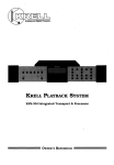
Typical
System
Diagram.
Connection
LOUDSPEAKERS
Digital
components can
connect to different inputs
than are shown.
KSA AMPLIFIER
~R L
OUTPUT
PREAMPLIFIER
REFERENCE
64
I
il
DAT DECK
CD TRANSPORT
I
SATELLITE
RECEIVER
DAT DECK
PAGE13
CONNECTIONS -
TAPE MONITOR INPUTS
1 Digital
2 Digital
AND OUTPUTS
only tape output: Intended for CD-R or DAT
monitor inputs using auto selection
system
1 AT&Tnormally active, priority
over coax input
1 coax selected by default system
The digital signal at the tape output is the active digital input
signal selected.
The use of external clock or TimeSync feature
does not interfere with the output of the selected digital signal to
the tape output RCA.
The digital
TAPE MONITORinput allows either an AT&Tinput or
a coax input. The AT&Tis the active input if there is digital data
present at the AT&Treceiver.
If no data is present at the AT&T
receiver, the internal default logic automatically selects the coax
input.
~
The use of the MONITORbutton on the front panel selects
the
TAPEIN inputs on the rear panel. The use of this input does not
interfere
with the input selection being sent to the Digital tape
output.
NOTE: The Tape input can also be used as an additional
source
input, without use of the digital record output. This input signal
cannot appear at the digital
tape output jack.
CAUTION:The Tape output is a digital
as an analog output to drive front
preamplifier or cassette recorder.,
NOTE: The selected
output regardless
digital
of the
signal and can not be used
end components such as a
input is always routed
SOURCE/MONITORbutton
PAGE 14
to the tape
position.
CONNECTIONS
DIGITAL SOURCE TO D/A CONVERTER INTERLINK CONSIDERATIONS
Care should be taken in selectihg the type of cable used to link the
digital
source to your Processor,
We suggest the AT&Twide-band
width fiber optic cable be used. The AT&Tformat has a bandwidth
of approximately
50 MegaBit. This allows accurate transmission
of the digital bit stream without data corruption and proves to be
sonically
superior.
If the AT&Tformat is not available,
a high
quality qual~ fiber optic (Toshiba format) link can work well.
Using a fiber optic interconnect
reduces ground loop problems
often associated
with quality audio systems.
If coaxial cable is used, it should be non-capacitive
and have a
bandwidth in excess of 10MHz to prevent drop-out errors.
For
best results
with coaxial
cable we recommend the AES/EBU
balanced format.
The AES/EBU format is a + 5 volt balanced
digital
transmission.
Because of the high voltage balanced format, this system, allows for accurate data transmission
and has
great sonic advantages over standard single-ended
coaxial or
Tosh fiber optic terminations.
The AES/EBU coaxial cable must
have two conductors and a shield for balanced termination.
SPECIAL NOTE: When the Tosh/C 1 input is used, the Processor
will default and acknowledge the Tosh input first if cables are
inserted
in both the Tosh and Coax 1 inputs.
When using the
Coax 1 input you must remove the Tosh cable from the Processor
or turn that unit off before Coax 1 can be used. If the Tosh input
is not in use, the Coax 1 input will not be effected.
PAGE 15
’"’’",’
CONNECTIONS
TIMESYNC
TimeSync is a proprietary
interlink
system that enables a Krell
CD transport
and REFERENCE 64 to link and run on the CD
transport
clock. The TimeSync system can only be had on specific
Krell transports.
The DT- 10 and MD- 10 CD Transports
come
standard
with the TimeSync output.
The MD-20 can have the
TimeSync installed
as a new or additional
purchase option.
The TimeSync input allows the clock of selected Krell transports
to become the system clock. The jitter
normally induced into the
system, due to the recovery module that separates
the data and
the clock, is eliminated.
The recovered clock is ignored and the
clock in the transport will be the clock used in the Processor.
The use of the TIMESYNCinput requires
that the CD transport
used be a Krell equipped with the TimeSync/Special
AT&T/ST
output transmitter.
It also requires that the TimeSync output of
the CD Transport
be connected
to the TimeSync input of the
REFERENCE64 processor
using an AT&T/ST optics
cable.
The
TimeSync is in addition to the connections used to carry CD disc
data. The CD data can be carried via any other of the outputs,
coax, balanced XLR, or AT&Toptics.
PAGE16
CONNECTIONS
The operation
of the Processor utilizing
the TimeSync feature
requires that the data input be selected first and then the
The TimeSync and the DATAinput
TimeSync input be selected.
selected must be from the same source. If the DATAand TimeSync
are from different
sources the processor will, after a very short
period,
go into a MUTEmode. The MUTEmode can be cleared by
pressing the TimeSync button again, reselecting
a DATAinput,
and then optionally
selecting
the TimeSync if this input is
connected to the same data source.
NOTE: The use of the TimeSync feature does eliminate the jitter
normally encountered in the normal decoding of the digital
data
stream;
however,
the proprietary
Krell DATA RECOVERYAND
JITTER RF_~ECTION MODULE reduces
jitter
to an almost
unmeasurable
level.
TimeSync provides an additional
level of
Jitter reduction.
NOTE: The use of the TimeSync button without having an actual
TimeSync input or a mismatched input( different
input selected
than the input from which the TimeSync signal originates)
will
cause the processor
to go into MUTEmode. The TimeSync input
select LED will flash when the mismatch condition or no input is
present. The frequency indicator LEDwill still indicate the input
frequency of the selected input.
NOTE: The TimeSync system
fiber optic cable.
is
connected
PAGE17
with an AT&T ST type
CONNECTIONS
HOW TO CONNECT AT&T CABLES:
a. Remove the plastic
cover from the outside
of the AT&T
transmitter
(located on Transport) and receiver (located on Processor).
b. Locate the slot
on the top of the AT&Treceptacle.
c. Locate the key on the top of the AT&Tcable.
d. Remove the plastic
cap from both ends of the AT&Tcable.
e. Slide the cable connector into the AT&Treceptacle
sliding into the designated slot.
with the key
f. Gently push the connector into place, depressing the internal
spring, and twist the outer collar clockwise to secure the connection.
g. Use the same procedure
for the transport
PAGE18
and D/A Processor
OPERATION
INPUT SELECT SWITCHING
The REFERENCE64 has multiple
digital
inputs.
Each input has
its own input switch and direct path to the digital
Processor.
When an input is selected, the corresponding LED will illuminate.
ST
XLR
TOSH/C1
AT&Tfiber optic input
Balanced AES/EBU digital
input
Toshiba fiber optic input (Priority)
and Coaxial input
Coaxial input
COAX 2
INPUT
FREQUENCY INDICATORS
When the input signal locks with the Processor,
the corresponding input frequency LED will illuminate.
The input frequency is
automatically
selected by the Processor.
As an example, if you
select the AT&Tinput from a CD transport,
the 44.1 KHz LED will
illuminate.
FREQUENCY
TYPICAL
32.0
44.1
48.0
Satellite
Decoder digital
Compact disc player
D.A.T. Player
KHz
KHz
KHz
SOURCE
PAGE 19
output
OPERATION
SOURCE AND MONITOR SELECTION
The SOURCEbutton directs
the signal from the Processor input
selection
section to the DACand analog output stage. The source
button must be depressed to listen to the selected input through
the main audio system.
The MONITOR button
routes
the output
of the component
connected to the digital
tape loop input to the DACand analog
output stage. This enables you to listen to the digital tape recorder
output while recording.
PHASE SWITCH
The analog output
In some recordings
creating
unusually
phase of the REFERENCE64 can be changed.
the master tape was recorded out of phase,
poor sounding recordings.
~
The REFERENCE 64 can shift
the absolute
output
phase 180
degrees to correct for this anomoly. To change the phase from 0
degrees to 180 degrees,
press the 180 DEG button.
To change
back to normal phase, press the 0 DEG button.
Utilizing
the
Phase Shifting can, in some instances, restore life to a previously
dull sounding recording.
EMPHASIS
LED
Emphasis is a recording technique that accentuates
the treble
region of recorded music. Discs and/orTracks that were recorded
with Pre-emphasis
will cause the Emphasis LED to illuminate.
When the Emphasis LED is lit the appropriate
complementary
circuitry
(De-emphasis)
is activated
to provide a fiat output
response.
PAGE20
OPERATION
OPERATING INSTRUCTIONS
1. Select an input with the Input switch. Notice the Signal LED
will illuminate when the digital ~ource is turned on and has linked
with the Processor. Once this link is complete, the Processor is
ready to pass a signal. If you are utilizing the TimeSync interlink,
press the TimeSync button at this time. The TimeSync LED will
illuminate.
2. Be sure that your preamplifier’s
volume control
completely to the OFF (lowest volume) position.
is turned
3. Turn ON your components, remembering that the last component to be energized should be your amplifier.
The amplifier
should only be turned ON after
all other components in the
system have been on for at least two minutes. This will insure that
there will not be any large pulse created when the amplifier is
turned on.
4. Switch the source selector
of your preamp to the position
correlating
to your chosen input connection for the
REFERENCE 64.
5. You may now start
satellite.
playing
your digital
source,
DAT, CD or
6. Slowly turn the volume control up to the lowest level you can
hear. Check to see that both channels
are working correctly
before advancing the volume.
PAGE21
OPERATION
NOTE: While your REFERENCE64 will perform beautifully
from
the moment you turn it on, it requires
a minimum warm-up
period of 8 hours before it begins to show its strongest
sonic
qualities.
It will continue to improve over time. Discrete components are utilized
in the analog output stage and the warm-up
period allows them to reach thermal equilibrium.
Your installation
is now complete. Should you have any further
questions which are not covered in the remainder of this Reference, contact your authorized
Krell dealer.
We wish you many
hours of listening fulfillment.
PAGE22
QUESTIONS AND ANSWERS
Q. My CD player has both fiber
one should I use?
optic
and coaxial
outputs.
Which
A. Given a choice, we prefer the’AT&Toptical link due to its ability
to completely isolate
the grounds between the digital
source
component and the Processor.
This minimizes the possibility
of
ground loops in the digital
components. The AT&Tformat also
has the added benefit
of substantially
higher bandwidth than
coax or the standard fiber optic interface.
If a coax cable must be
used, we suggest the AES/EBU balanced format. This interconnection utilizes
a + 5v digital
format and has the additional
benefit of balanced termination.
Q. Will I damage my REFERENCE64 if
the time?
I leave
the power ON all
A. No. The Class A discrete analog circuits
perform more consistently once they reach thermal equilibrium.
This Processor has
been designed
to be left on at all times.
The REFERENCE64
draws less than 50 watts out of the AC mains socket.
NOTE: For the protection
of your Processor,
we recommend
disconnecting
the AC cord from the wall outlet
before any
electrical
storms or if you plan on being away from home for
prolonged periods of time.
Q. Do I have to switch the Sampling Frequency when I go between
my CD and DAT?
A. No. Your REFERENCE 64 automatically
frequency and does all necessary switching.
PAGE23
senses
the
input
QUESTIONS
Q. I am not getting
be wrong?
AND ANSWERS
any sound through
the Processor.
What could
A. Most likely there has been a simple mistake in installation.
Check all connections IN and OUTof the Processor. Is the digital
source component powered? Check all power connections.
Have
you selected the correct source on your preamp? Check the front
panel LED’s for Power Supply stability.
If you still have no sound,
turn off the power and contact your dealer.
Q. I have some very fine audiophile interconnect
cable which has
superior sonic characteristics.
Can I use this for my coaxial digital
input?
A. You may experiment with any high quality cable. Do note that
most audio interconnect cable is not designed to carry the ultrahigh frequency information of the digital bit stream.
NOTE: For the REFERENCE 64, we recommend non-capacitive
coaxial
cable which has a bandwidth in excess of 10MHz and
excellent shielding properties.
PAGE 24
QUESTIONS AND ANSWERS
Q. While listening
periods of silence
tioning?
to my REFERENCE64 1 experience
occasional
through my speakers. Is my Processor malfunc-
A. Drop outs are caused by two primary reasons. First, drop outs
can be caused by data corruption.
Corruption in the data may be
due to a poor input connection, damaged or dirty source material,
or interconnects
which do not have enough bandwidth.
The
second item that causes the Processor to reset is the presence of
a transient
spike on the incoming AC power line. The Processor
is resetting all of its digital processing circuits so that it can be
assured all are properly synchronized.
Try changing your source
material and check your connections.
If these are not the cause,
speak with your dealer about obtaining different
cabling. If you
are using fiber optics, and source material and connections are
not the problem, speak with your authorized dealer.
Q. Since I installed
hum that increases
in my system until
malfunctioning?
the Processor in my system I have a low level
as I turn up the volume. There was no hum
I added the Processor.
Is the Processor
A. The fact that there was no hum in your system until you added
the Processor indicates
that you have a ground-loop
problem.
Often changing the interconnect
to a fiber optic cable will
eliminate this problem. The way the digital Processor and digital
source are connected to the AC mains often can be the cause of
grounding problems. Check for loose interconnect
cables
and/or bad electrical
connections.
Consult your dealer or Krell
for individual
system suggestions if this hum persists.
PAGE25
SPECIFICATIONS
FREQUENCY RESPONSE
-. l dB at 4Hz & 20 KHz
SIGNAL TO NOISE
100 dB A weighted
DIGITAL-TO-ANALOG
KRELL DAC Modules
SHIELD
CONVERTER
in custom
THERMAL STABALIZATION
PROCESSING
KRELLwritten software calculated
Serial
Motorola 560001 processors
channel in series configuration
LINEARITY
+.3dB at -90dB
THD +N
.011%
CHANNEL SEPARATION
> llldB at 1KHz
ANALOG OUTPUT
2.4 volts
VOLTAGE
DIMENSIONS
19.10" WIDE
14.00" DEEP
"5.63" TALL(stacked
SHIPPING
54 pounds
’~.
with feet)
WEIGHT
PAGE26
through 4 custom configured
running at 34MHz, two per
WARRANTY AND SERVICE
WARRANTY AND SERVICE
INFORMATION
There are no user-serviceable
~arts inside the REFERENCE64.
The REFERENCE64 has a limited
warranty of five years parts
and labor.
Return freight
is included
in the warranty.
The
warranty period begins on the date of purchase and is activated
with the return of the enclosed Warranty Card and a copy of the
Sales receipt.
Please return the Warranty Card immediately after
successful
installation
and operation are completed.
The warranty for Krell products is valid only in the country to
which they were originally shipped and at the factory. If you think
there are problems with your unit, please contact your dealer,
distributor
or the factory immediately.
The operating voltage of this unit is determined by the factory and
can only be changed by an authorized
KRELLdistributor
or the
KRELLfactory. Any unauthorized voltage conversion will void the
warranty.
Should the operating
voltage of your REFERENCE64
require changing, contact KRELLIndustries.
Please do not return any unit to KRELLfor repair without first
calling to discuss the problem and to obtain a Return Authorization number. Freight to the factory or distributor
is your responsibility.
Return freight to you will be paid by the factory or
distributor.
Any unauthorized disassembly,
updates or modifications performed to the unit will void the warranty.
PAGE27
Krell Industries, Inc.
¯ 45 Connair Road, Orange CT 06477-3650
TEL 203-799-9954
FAX 203-891-2028
E-MAlLkrell@krellonline,
com
WEBSITEhttp: //www.krellonline.
com
© 2001 Krell Industries,
(REF649303)
Inc.