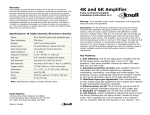
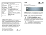
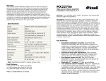
1
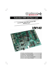
IR230 Infrared Receiver Specifications: Specifications Infrared carrier frequency: Indoor reception range: Nominal reception angle: Maximum wire length: Wire requirements: Power requirements: Dimensions: Cut out hole dimensions Cord length 30-60kHz 30-40 feet (6-8 meters) 50 degrees off axis 1000’ (300m) or more with larger gauge wire 3 conductors, minimum 24-gauge to 200’; 22-gauge up to 500’; 20-gauge to 1000’ Unregulated 12VDC, 40mA IR230 Peep-hole Infrared Receiver Installation Instructions v1.2 Warning: To be installed and/or used in accordance with appropriate electrical codes and regulations. Introduction: Thank you for your purchase of a Knoll IR230 infrared receiver. This receiver features the ability to pick up a remote control infrared signal and relay it on wires to another location up to 1000’ (or more). 0.6” x 2” (15mm x 50mm) ½” (12mm) 75” (2 meters) Requires 12VDC power supply, emitter(s) and IR54, or IR55 connection block. Features: Warranty Knoll Systems warrants its products sold in the USA and Canada by authorized Knoll dealers to be free of defects in materials and workmanship. This warranty extends for three full years from the date of purchase by the original consumer. Any products returned to Knoll Systems and found to be defective by Knoll Systems within the warranty period will be repaired or replaced at Knoll Systems option, at no charge. Knoll Systems will not be responsible for the actual cost of installation or removal of the product, nor for any incidental or consequential damages. Some states do not allow the exclusion or limitation of incidental or consequential damages, so the above limitation may not apply to you. This warranty gives you specific legal rights. You may have additional legal rights that vary from state-to-state. Knoll Systems www.knollsystems.com 145 Tyee Drive Point Roberts, WA 98281 12140 Horseshoe Way, Richmond BC V7A 4V4 Telephone: (604) 272-4555, Fax: (604) 272-5595 Made in China Knoll Systems All Rights Reserved Primarily designed to for mounting in panels, doors, cabinets etc. Will relay almost all remote control types (except some B & O and Elite models). Can be connected with almost any 3-conductor wire including cat 5. Requires very little power. Suggest using PS1202 12 VDC (200 mA) for up to 5 IR21s. Up to 10 or IR230s, IR21s and other compatible models can be connected in a single system. Brass and white color bezel supplied Small and CFL and sunlight ready design Installation Tips 1. Follow all local electrical & building code requirements. 2. The IR230 is usually mounted in a panels, door, cabinet or plate. It does not normally require a junction box. For easy installation and to ensure reliability, it is suggested that a PS1205 (500 mA) 12 VDC unregulated power supply, IR31 (single) or IR34 (dual) emitters and one of the following: IR54 (decora inwall style, 4 output) or IR55 (tabletop style, 4 output) connection block, be used. 3. Wires can be solid or stranded, shielded or unshielded with a minimum of 28-gauge for runs under 200’, 22-gauge for runs under 500’ and 20-gauge for runs up to 1000’. Wires can be looped from IR230 to IR230 or home run. Home runs generally offer more reliability and future flexibility. 4. IR230s can be mixed and matched in larger systems with up to 10 infrared receivers, such as the Knoll IR100 or IR220. 5. Drill a ½” (12 mm) in any flat surface such as a door. Pass the lead and the body of the IR230 through the hole. Screw on the brass or white bezel. Next secure the IR230 with the nut provided. Do not over tighten the nut. 5. To wire the system together, connect the IR230 12V, GND and IR SIG terminals to the corresponding IR54 or IR55 terminal. Prepare the wire leads from the IR230 by stripping about ¼” of the insulation from each of the three leads. Strictly observe polarity. The white conductor is the IR SIGNAL, the middle conductor is the 12 volts and the other outside black conductor is the ground. IR230 PS1202 Panel 12 V DC Power Supply nut Bezel White Wire IR230 White Wire Receiver IR55 12V GND SIG Connection Block Note: IR23a’s are wired in parallel IR31A CD IR34A 171 Dish IR34A 7. Now, plug in the PS1205 for up to ten infrared receivers. 8. The infrared system is usually left plugged in all the time (to an unswitched outlet) as it uses very little power. 9. Test the infrared system to see if it is working properly. Bright sunlight and passive infrared security systems can lower the distance that remote controls can work with an IR230 receiver. 10. If you have any questions or concerns, please call and ask for infrared technical support at 1 800 566 5579. The Help Line is open from 7:30 a.m. to 5:00 p.m., Monday to Friday, Pacific time. 6. Next, plug the single or dual emitters into the IR54 or IR55 connection block.