1
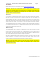
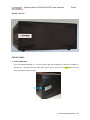
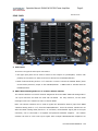
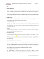
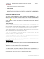
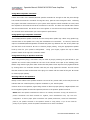
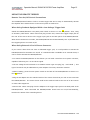
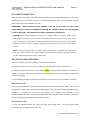
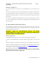
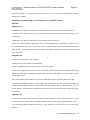
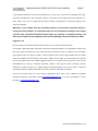
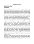
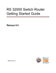
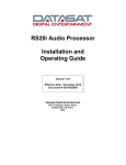
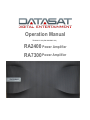
Operation Manual TM-H628 V1.00 (9301H62800V1.00) RA2400 Power Amplifier RA7300 Power Amplifier Operation Manual, RA2400 & RA7300 Power Amplifiers Page 2 PLEASE READ FIRST CAUTION: To reduce the risk of electrical shock, do not remove the cover (or back). No user serviceable parts inside. Refer servicing to qualified service personnel. WARNING: To reduce the risk of fire or electric shock, do not expose this appliance to rain or moisture. WARNING TO REDUCE THE RISK OF FIRE OR ELECTRIC SHOCK, DO NOT EXPOSE THIS APPLIANCE TO RAIN OR MOISTURE. The lightning flash with arrowhead, within an equilateral triangle, is intended to alert the user to the presence of uninsulated “dangerous voltage” within the product’s enclosure that may be of sufficient magnitude to constitute a risk of electrical shock to persons. The exclamation point within an equilateral triangle is intended to alert the user to the presence of important operation maintenance (servicing) instructions in the literature. PRECAUTIONS: The RA2400/RA7300 amplifier is a wideband design with substantial power output capability. Certain precautions must be taken to ensure proper operation. Never expose the amplifier to moisture. Never plug an input cable into the RA2400/RA7300 while the unit is turned on. Never apply the “thumb test” (touching the “hot” lead of the input cable with your finger) to the tip of the input cable or input jack of the RA2400/RA7300. RF rectification and/or hum will be created and could cause damage to the loudspeakers. Datasat will not be responsible for damage to the loudspeakers due to improper use of the equipment. Under no circumstances should the output terminals of the RA2400/RA7300 be short-circuited. Avoid restricting the airflow around the RA2400/RA7300. Good airflow is necessary to ensure proper cooling and trouble-free operation. Ensure that the rated power handling of the loudspeakers connected to the RA2400/RA7300 is appropriate to use with the output power of the amplifier. The warranty on the RA2400/RA7300 does not cover damage to loudspeakers. Document # 9301H62800 Ver. 1.00 Operation Manual, RA2400 & RA7300 Power Amplifiers Page 3 SAFETY INSTRUCTIONS Read all the safety and operating instructions before connecting or using the RA2400/RA7300. All warnings on the unit and in this operating manual should be adhered to. All operating and use instructions should be followed. Do not place/use the unit near water; for example, near a bathtub, washbowl/sink, laundry tub, decorative water features (waterfalls/fountains), in a wet basement or near a swimming pool. This unit is not intended for outdoor use. This unit should be installed so that its location or position does not interfere with its proper ventilation. For example, it should not be situated on a bed, sofa, rug or similar surface that may block its ventilation openings. It should also not be placed in a built-in enclosure, such as bookcase or cabinet, that may impede the flow of air through its ventilation openings. The unit should be situated away from heat sources such as radiators, fireplaces, hot air ducts, heat registers, stoves and/or other devices (including amplifiers) that produce heat. The unit should be connected to a power-supply outlet only of the voltage and frequency marked on its rear panel. The AC power cord should be routed so that it is not likely to be walked on or pinched, especially near the plug, convenience receptacles or where the cord exits from the unit. Clean unit only as recommended in this instruction manual. The unit’s AC power cord should be unplugged from the wall outlet when the unit is to be unused for a long period of time. Care should be taken so that objects do not fall, and liquids are not spilled, into the unit through any openings. The unit should be serviced by qualified service personnel when: a. The power cord or plug has been damaged; or b. Objects have fallen, or liquid has been spilled, into the unit; or c. The unit has been exposed to rain or liquids of any kind; or d. The unit does not appear to operate normally or exhibits a marked change in performance; or e. The device has been dropped or the enclosure damaged. To prevent electric shock, do not use a ground lift plug/adapter. Also, do not use the polarized plug with an extension cord, receptacle or other outlet unless all the blades can be fully inserted to prevent blade exposure. Document # 9301H62800 Ver. 1.00 Operation Manual, RA2400 & RA7300 Power Amplifiers Page 4 TABLE OF CONTENTS Page 2 ........................................................................................................................................ Please Read First 3 ..................................................................................................................................... Safety Instructions 4 ....................................................................................................................................... Table of Contents 6 .............................................................................................................................................. Introduction 6 ................................................................................................................................................... Features 7 ................................................................................................................................................. Unpacking 7 ................................................................................................................................................. Placement 8 ........................................................................................................................................... Rack Mounting 8 ................................................................................................................................................Front Panel 9-10 .................................................................................................................................................Rear Panel 11 ................................................................................................................... Connecting the RA2400/RA7300 11 ...................................................................................................................................... Input Connections 11-12 .................................................................................................................................. Dip Switch Settings 13-14 ................................................................................................................................ Speaker Connections 13 ............................................................................................................................... Wire Recommendations 13 ....................................................................................................................... Polarity and Speaker Phasing 14 .................................................................................................................. Using Wire to Speaker Terminals 14 .........................................................................................................Using Spade Lugs to Speaker Terminals 15 ...................................................................................................... Using Banana Plugs to Speaker Terminals 15 .......................................................................................................................... Running Cable to Speakers 15-16........................................................................................................................... Using the Remote Trigger 15 ..................................................................................................................Remote Turn On/Off Connections 15 ........................................................................ When Using Products Equipped with a Low Voltage Trigger Jack 15 ..............................................................................................When Using External AC to DC Power Converter 16 ................................................................................................................................. AC Power Connection 16 .......................................................................................................................... RA2400/RA7300 Operation 16 ....................................................................................................................................... Manual Power On 16 ....................................................................................................................................... Manual Power Off 17 ............................................................................................................................... Automatic (Trigger) On 17 ........................................................................................................... AC Line Connector and Power Cord(s) 17 ................................................................................................................................... Main Circuit Breaker 18 .................................................................................................................................Care and Maintenance Document # 9301H62800 Ver. 1.00 Operation Manual, RA2400 & RA7300 Power Amplifiers Page 5 18 ................................................................................................................................................... Cleaning 18 ......................................................................................................................................... Troubleshooting 18 ..................................................................................................................................... Protection Circuitry 18 ........................................................................................................................ Datasat Service Information 19 ...............................................................................................................A Few Words About Hum and Noise 20-21 ......................................................................................... Potential Ground Loops in a Complex A/V System 22 ..................................................................................................................... RA2400/RS7300 Specifications 22-23........................................................................................................................... Datasat Limited Warranty 23 .....................................................................................................................................................Returns 24 ................................................................................................................................... Contact Information Thank you for choosing the Datasat RA2400 / RA7300 Amplifiers! Document # 9301H62800 Ver. 1.00 Operation Manual, RA2400 & RA7300 Power Amplifiers Page 6 DATASAT RA2400 / RA7300 AMPLIFIERS Introduction Congratulations! Thank you for purchasing the Datasat RA2400/RA7300 Power Amplifier(s). Designed, engineered and manufactured in the United States, it has been carefully designed to deliver the best possible audiophile-grade performance as well as the most reliable operation. The RA7300 is a seven channel amplifier and the RA2400 is a two channel amplifier. This manual covers both models with the differences being the number of channels, specifications, design and/or power output. In order to receive the maximum enjoyment from your new amplifier, please take a few minutes to read this manual. The important information will help to ensure that the RA2400/RA7300 is properly configured for trouble-free operation with the rest of your system’s equipment. If you have any questions about this product, its installation or operation, please contact: Datasat USA technical support via e-mail at [email protected] or call 1(888) 428-2268. Customers located in Europe may email [email protected] and/or call +44 (0)118 934 9199. Features Your new RA2400/RA7300 amplifier is a state of the art, high performance audio component. Its circuit topology is fully-differential and balanced from input to output. Both model amplifiers utilize current feedback for improved speed and a DC servo to minimize any DC offset. Custom-designed torrodial transformers with multiple secondary windings drive the high current power supplies effectively making each channel a complete monoblock amplifier. To ensure signal purity, each amplifier module employs advanced optically coupled protection circuitry that is outside the signal path. Designed specifically for the rigors of rack-mounting, both model amplifiers use a temperature controlled, fan-cooled heat tunnel with dual thermal sensors to draw cool air in from the sides and exhaust warm air from the rear. The fan is calibrated to be silent during low-power operation and any fan noise will be masked by program content during high-power output. Unpacking The carton and packing materials used in shipping your RA2400/RA7300 amplifier are specially designed to protect it from the shocks and vibration of shipping. We strongly suggest that you save the carton and packing materials to re-use if you move or if the unit needs to be shipped for any reason. Should you discover that your RA2400/RA7300 has been damaged during shipping, please contact your dealer or Datasat immediately and request the name of the carrier so a written claim may be made. Document # 9301H62800 Ver. 1.00 Operation Manual, RA2400 & RA7300 Power Amplifiers Page 7 Datasat customer service can be reached by email at [email protected] IMPORTANT! THE RIGHT TO A CLAIM AGAINST A PUBLIC CARRIER CAN BE FORFEITED IF THE CARRIER IS NOT NOTIFIED PROMPTLY IN WRITING AND IF THE SHIPPING CARTON AND PACKING MATERIALS ARE NOT AVAILABLE FOR INSPECTION BY THE CARRIER. SAVE ALL PACKING MATERIALS UNTIL THE CLAIM IS SETTLED. Placement It is normal for the RA2400/RA7300 amplifier to become warm during standard home operation. Note that during high-level playback into low impedance speaker loads, when the amplifier must naturally dissipate more heat, the heat sinks inside the unit will become much warmer and the speed of the internal cooling fan will increase (to dissipate the heat). To ensure proper cooling and maintain trouble-free operation, it is imperative to provide the amplifier with adequate ventilation. The RA2400/RA7300 should never be placed in a cabinet with other heat-producing components or in an enclosure lacking free airflow. The amplifier should also be kept away from external sources of heat such as radiators and/or hot-air ducts. Rack Mounting Your RA2400/RA7300 may be mounted in a standard 19-inch rack. Note that the rack mount panels have both front and back mounting holes. The RA2400/RA7300 is heavy so support from the back is required. Also, ensure that the screws used to attach the amplifier are appropriate for the rack and are adequately gauged to support the weight of the amplifier. Note that the RA2400/RA7300 amplifiers shipped from the factory come with the rack mount side panels pre-attached. If you choose to not rack mount your amplifier, simply remove the rack mount side panels and install the standard side panels (included) in their place. CAUTION: IF THE RACK MOUNT SYSTEM YOU ARE USING CANNOT SUPPORT THE WEIGHT OF YOUR RA2400/RA7300(S), BE SURE TO MOUNT THE AMPLIFIER(S) ON A STRONG, WELLSUPPORTED TABLE OR SHELF. Document # 9301H62800 Ver. 1.00 Operation Manual, RA2400 & RA7300 Power Amplifiers Page 8 RA2400 / RA7300 FRONT PANEL A Power Switch Plate Turns the RA2400/RA7300 on. The front panel LED will illuminate blue when the amplifier is powered on. Note that the rear panel main power switch must be in the ON position for the front panel power switch to work. Document # 9301H62800 Ver. 1.00 Operation Manual, RA2400 & RA7300 Power Amplifiers REAR PANEL Page 9 RA7300 Shown A Audio Inputs There are two types of audio input connections: ● XLR type input jacks can be used to connect to the outputs of a preamplifier, receiver with preamp-out connectors or other sound source devices for the RA2400/RA7300. ● DB25 “balanced analog audio in 1-8” connector is used to connect the Datasat RS20i (home cinema audio processor) output to the RA2400/RA7300. A DB25 cable is included with the RA2400/RA7300. B DB25 “Balanced Analog Audio In 1-8” Connector Selector Switches The selector switches are used for channel assignment when the DB25 “balanced analog audio in 1-8” input connector and cable are used with the RS20i. For easy reference, use the white rectangles next to the switches to write in channel labels. Note: The selector switches can be used to bypass the Subwoofer channel (input from DB25 “balanced analog audio in 1-8”) from the RA2400/RA7300. Since the selector switches do not affect the DB25 “analog audio pass thru 1-8” connector, the Subwoofer signal (fed to the input connector) can be connected to a separate self-powered subwoofer amplifier. The selector switches can also be used route input signals when multiple RA2400/RA7300 amplifiers are Document # 9301H62800 Ver. 1.00 Operation Manual, RA2400 & RA7300 Power Amplifiers Page 10 used. C Remote Trigger Input The remote trigger input is used for remote activation of the RA2400/RA7300 by an external device. The trigger is used to connect in a separate device in the system so when it powers on it also powers on the RA2400/RA7300. Use the Remote Trigger jack to connect a compatible preamp, source device or other product (with a 3.3-24VDC output) that that you wish to use to remotely power on the RA2400/RA7300. D Speaker Outputs Use the Speaker Output binding posts to connect the RA2400/RA7300 to your speakers. The binding posts are color coded to help ensure proper polarity. E Product Serial Number Document this number for future reference or when contacting Datasat customer service/techsupport. You will be required to provide the serial number when reporting issues and/or to verify warranty. F AC Input Use the included power cord(s) to connect your amplifier to an AC power source. The RA2400 uses one power cord and the RA7300 uses two. G Master Power Switch The rear panel Master Power switch(es) selects power to the amplifier, either on and off. The switch(es) must be in the ON position for the front panel power switch and remote trigger to work. Note the RA2400 has one master power switch and the RA7300 has two (both should either be on or off). H DB25 Analog Audio Pass-Thru 1-8 Connector This connector routes signals from the DB25 input jack, through the RA2400/RA7300 for connection to additional amplifiers. For example, the Subwoofer input channel can be switched away from the RA2400/RA7300 and still be routed to the pass-thru connector. This allows the Subwoofer signal to be fed to a separate amplifier. Also, the 8-channel analog audio output from the Datasat RS20i can be routed to multiple RA2400/RA7300 amplifiers. I Power Supply Voltage Indicator Each RA2400/RA7300 is marked at the factory by a green dot to indicate the power requirements. Be certain to use only the appropriate voltage as marked. Plugging an 117V Document # 9301H62800 Ver. 1.00 Operation Manual, RA2400 & RA7300 Power Amplifiers Page 11 amplifier into a 230V supply will damage the amplifier. J Ground Terminal Occasionally, audible hum arises when a preamplifier is connected to the RA2400/RA7300. Should this occur, running a ground wire between the preamplifier and the RA2400/RA7300 may restore noise-free operation. CONNECTING THE RA2400/RA7300 When making connections between any source component and the RA2400/RA7300, or when making connections to any speaker, be certain that both the input devices and the RA2400/RA7300 are turned OFF. This will ensure that no unwanted signals/transients will be produced and possibly damage equipment or speakers. It is always best to power off all equipment before making any connections. Input Connections Connecting the RA2400/RA7300 to your source equipment is simple. Using high-quality audio interconnect cables, match the output channel designations on the rear of your source equipment to the input jacks on the rear panel of the RA2400/RA7300 that have the same channel name. ● When making connections with the XLR connectors, DB25 connector or any interconnect cables, make certain to gently but firmly insert the plugs into the jacks. ● Make sure the connections are firmly seated and locked in. Loose connections may cause intermittent sound and could damage your speakers. ● Note that some quality plugs may be very tight and it is important to ensure a proper, secure connection between the interconnection cable and the input jack. ● Be careful to match the type of input you have decided to utilize on your RA2400/RA7300 with the same type on your preamp or other source device. Dip Switch Settings When using the DB25 connectors, be sure that the dip switches on the RA2400/RA7300 have been properly set for the desired channel being used: ● They should all be in the off position if you are using the XLR inputs. ● There will be no output if the switches are in the wrong position. ● The dip switches are used to assign the DB25 input connector (balanced analog audio Ch1-8) to the RA2400/RA7300. Note that it does not affect the pass-thru connector (located directly below the input connector). See the next page for an example of dip switch settings. Document # 9301H62800 Ver. 1.00 Operation Manual, RA2400 & RA7300 Power Amplifiers Page 12 Dip Switch Example: In a typical 7.1 set up using a separate self-powered sub you would assign the dip switches as follows: RA2400 From RS20i DB25 Audio In select switches: DB25 Input 1 ON = RA Channel A DB25 Input 2 ON = RA Channel B DB25 Input 3 ON = RA Channel C DB25 Input 4 OFF DB25 Input 5 ON = RA Channel D DB25 Input 6 ON = RA Channel E DB25 Input 7 ON = RA Channel F DB25 Input 8 ON = RA Channel G Notes: RA = RA2400/RA7300 Input 4 = subwoofer channel from RS20i “Input” on RA = “channel” output on RS20i In the example, the settings allow Input 4, channel four (the subwoofer channel from the RS20i), to bypass the “Balanced Analog Audio In 1-8” DB25 connector so that the subwoofer signal can connect to an external subwoofer amplifier via the “Analog Audio pass-thru 1-8” DB25 connector. Note that the pass-thru connector outputs are not affected by the dip switch settings; in other words, the DB25 channel inputs are passed directly to the pass-thru DB25 connector below. PLEASE CONSULT WITH DATASAT OR YOUR INSTALLER/DEALER IF THERE IS ANY DOUBT. Document # 9301H62800 Ver. 1.00 Operation Manual, RA2400 & RA7300 Power Amplifiers Page 13 SPEAKER CONNECTIONS To ensure the high quality signals produced by your RA2400/RA7300 are carried to your speakers without loss of clarity or resolution, we recommend that you use high quality speaker wire. Many brands of wire are available; the choice may be influenced by the distance between your speakers and the RA2400/RA7300, the type of speakers you use, personal preferences or other factors. Wire Recommendations Regardless of the brand or type of speaker wire selected, we recommend that you use a wire constructed of fine, multi-strand copper with a gauge (AWG) of 14 or less. In specifying wire, the lower the number, the thicker the cable is. Wire with a gauge of 14 may be used for short runs of less than twenty feet. We do not recommend that you use any wires with an AWG equivalent of 16 or higher due to the power loss and degradation in performance that will occur. A pair of binding posts is provided to connect each RA2400/RA7300 output channel to your speakers. These posts will accept bare wire, spade lugs or banana type plugs. If bare wire is used for the connections, strip approximately 1/2 inch to 3/4 inch of insulation from the end of each wire and carefully twist the strands of each conductor together. Be careful not to cut the individual strands or twist them off. All strands must be used for optimal performance. Polarity and Speaker Phasing Correct polarity connections are important to ensure proper speaker phasing. When speaker phasing is correct, the speaker cones will move in and out at the same time which preserves the imaging (sound) of the program material. Out-of-phase connections mean that some speaker cones will move in while others move out which can cause indistinct or confused imaging and muddled or cloudy sounds. To avoid incorrect phasing or polarity, be certain to use wire that has distinct markings, colors, stripes, wording, or grooves on each side of the speaker cable so you can keep polarity straight. When making connections to the RA2400/RA7300 and speakers you should adhere to a consistent pattern being sure to connect the correct set of wires from the RA2400/RA7300’s output channel to the desired speaker. Be sure to keep polarity straight. Example: From the RA2400/RA7300 ▪ Connect red wire for channel 1 positive to the red (+) terminal on speaker channel 1 ▪ Connect black wire for channel 1 negative to the black (-) terminal on speaker channel 1 When using cable with markings on one side only, traditional convention is to consider the marked side of the wire as the red or positive (+) connection and the non-marked side as the black or negative (-) connection. Document # 9301H62800 Ver. 1.00 Operation Manual, RA2400 & RA7300 Power Amplifiers Page 14 Using Wire to Speaker Terminals Loosen the knobs of the RA2400/RA7300 speaker terminals far enough so that the pass through hole inside the terminal is revealed. If using bare wire, pass the wire through the hole. Following the proper connection instructions for your system with regard to which terminals are used, twist the cap back to the terminal so that the connection is secured. The bare wire should make contact with the terminal metal. Be careful not to over tighten or use tools as this may break the delicate wire strands which will decrease your sound system’s performance. Using Spade Lugs to Speaker Terminals The RA2400/RA7300 speaker terminals will also accept 9mm spade lugs. When using spade lugs, connect them to the speaker wire using the manufacturer’s instructions. To connect, loosen the caps on the RA2400/RA7300/speaker terminals and place lugs between the slot of the plastic cap and the back of the terminal. Be sure to observe proper polarity, using the appropriate speaker hook-up icons for your system’s configuration. Using your fingers, tighten the cap to obtain positive contact of the lug to the connector metal. Using Banana Plugs to Speaker Terminals When using banana plugs, connections may be made by simply inserting the jack affixed to your speaker wire into the hole provided on the rear of the colored screw caps on the binding posts. Before using banana type jacks make certain that the plastic screw caps are firmly tightened down by turning them in a clockwise direction until they are snug against the chassis. This will ensure that the maximum metal surface area of the plug is in contact with the metal of the jack. Be certain to observe proper polarity. Running Cable to the Speakers Neatly run the cables to the speaker locations. Do not coil any excess cable, as this may become an inductor that can create frequency response variations in your sound system. Connect wires to the speakers, again being certain to observe proper polarity: Negative/black wire to the negative speaker terminal and positive/red wire to the positive speaker terminal. NOTE: While most speaker manufacturers adhere to an industry convention of using red terminals for positive connections and black terminals for negative, some manufacturers may vary from this configuration. To assure proper phase connections and optimal performance, consult the identification plate on your speaker terminals or the speaker’s manual to verify polarity. If you do not know the polarity of your speaker, consult the speaker’s manufacturer for further information. Document # 9301H62800 Ver. 1.00 Operation Manual, RA2400 & RA7300 Power Amplifiers Page 15 USING THE REMOTE TRIGGER Remote Turn On/Off Control Connections The RA2400/RA7300 features a built-in remote trigger that can be setup to automatically activate the amplifier when another device in the sound system is switched on. When Using Products Equipped With a Low Voltage Trigger Jack Switch the RA2400/RA7300’s rear panel power switch so that it is in the ON position. Then, using an accessory cable with a 3.5mm mono mini-plug on each end, connect the trigger-output jack on the rear of the source device to the trigger input jack on the back panel of the RA2400/RA7300. When these connections are made, the RA2400/RA7300 should automatically turn on/off whenever the triggering device is turned on/off. When Using External AC to DC Power Converter If your source device does not have a dedicated trigger jack, it is still possible to activate the RA2400/RA7300 for automatic turn on/off. If a switched outlet is available on an external device, it can be used to activate the RA2400/RA7300. ● To control the RA2400/RA7300 in this fashion you will need a small AC to DC power converter, capable of delivering a 3.3 to 24 volt DC signal. ● The DC voltage should terminate to a standard 3.5mm type mini plug (tip + and shield -). This type of converter may be obtained as a power adapter from many electronics retailers. ● When installing, press the main power switch on the back of the RA2400/RA7300 so that it is in the ON position. ● Plug the AC adapter into the switched outlet of the source device that you wish to use to activate the RA2400/RA7300. The source device could be the switched outlet at the rear of an AC receiver or other audio equipment. ● Connect the 3.5mm mini-plug from the adapter to the trigger-input jack on the back panel of the RA2400/RA7300. Once connected the RA2400/RA7300 should now turn on/off automatically, based on the status of the controlling device. Document # 9301H62800 Ver. 1.00 Operation Manual, RA2400 & RA7300 Power Amplifiers Page 16 AC POWER CONNECTION Once all audio and system connections have been made, connect the supplied power cord(s) to the RA2400/RA7300 first and then connect it to an AC power source. Note that the RA7300 uses two power cords whereas the RA2400 uses one. IMPORTANT: Make certain that the amplifier is turned off and that any auto on/off trigger device (if used) is off BEFORE connecting the amplifier’s power cord and plugging it into an AC outlet. Also make sure all other equipment is powered off. CAUTION: Do not plug the amplifier directly into the “Switched Accessory” outlet of another device! These outlets are intended for use with low current draw products having a low current draw, such as tuners, CD players or cassette decks. These cannot handle the high current draw of a power amplifier. Using these outlets for a power amplifier is a significant safety hazard and if used in this way will void warranty. NOTE: It is not recommended that you connect other power amplifiers or products with a high current draw, to the same AC power circuit as the amplifier. If this is unavoidable the Ultra-Soft-Start circuitry of your amp will prevent excessively high in-rush current. RA2400/RA7300 OPERATION After all connections have been made you are ready for operation First, one at a time, turn on the other components and processor in your sound system. It is always a good idea to turn on the amplifier LAST. This avoids the possibility of any power on “pops” or transients from other equipment being amplified and sent to your speakers where they may cause damage. To avoid damage to speakers, always start with a low volume level on your controller or preamp. Manual Power On Press the RA2400/RA7300’s front panel power plate (switch is underneath the plate). After a short pause the blue LEDs should illuminate, indicating power is on, and sound should be supplied to the speakers. The pause is intentional and protects your speakers from damage as the RA2400/RA7300 stabilizes. Note that the RA2400/RA7300 rear panel power switch(es) must be in the on position for the front panel power switch to work. Manual Power Off To turn the RA2400/RA7300 off, press the front panel power plate. The blue LEDs should extinguish and the amplifier should turn off. Document # 9301H62800 Ver. 1.00 Operation Manual, RA2400 & RA7300 Power Amplifiers Page 17 Automatic (Trigger) On First, make certain that the connection from the RA2400/RA7300 to the controlling device is correct. Turn on the controlling device and verify that the RA2400/RA7300 is automatically activated after a short pause. Remember, this pause is intentional and is used to protect your speakers from damage while the amplifier stabilizes. You may also hear a slight relay click during start up and this is also normal. Next, verify your RA2400/RA7300 automatically turns off when the controlling device is powered off. Once the controlling device is powered off, the RA2400/RA7300 should automatically turn off after a few moments. AC LINE CONNECTOR AND POWER CORD(s) Your RA2400/RA7300 is supplied with an internationally approved (IEC) power line connector that accepts the supplied detachable, high-current capacity power cord(s). The RA7300 has two power cords and the RA2400 comes with one. WARNING: UNDER NO CIRCUMSTANCES SHOULD THE ROUND THIRD PRONG BE CUT, BENT OR IN ANY OTHER WAY DEFEATED AS THIS MAY RESULT IN SEVERE SHOCK. Main Circuit Breaker Your RA2400/RA7300 is supplied with one or two heavy-duty magnetic circuit breaker(s). ● If power to your RA2400/RA7300 is interrupted, inspect the circuit breaker on the rear of the unit. ● If the circuit breaker is in the off position you may reset it to the on position to restore AC power. ● If the circuit breaker immediately trips to the off position, unplug the RA2400/RA7300 from the AC power source and contact the Datasat Technical Support, email [email protected] or (if you are located in or close to Europe) [email protected]. WARNING: ALWAYS TURN OFF THE RA2400/RA7300 AND UNPLUG THE POWER CORD(S) BEFORE MAKING ANY ELECTRICAL CONNECTIONS. Document # 9301H62800 Ver. 1.00 Operation Manual, RA2400 & RA7300 Power Amplifiers Page 18 CARE AND MAINTENANCE Cleaning If the RA2400/RA7300 becomes dirty, wipe it with a clean, soft, dry cloth. If necessary, first wipe the surface with a soft cloth slightly dampened with mild soapy water followed by a fresh cloth dampened with clean water. Wipe dry immediately with a dry cloth. NEVER use benzene, thinner, alcohol or any other volatile cleaning agent. Do not use abrasive cleaners, as they will damage the finish of the metal parts. Avoid spraying insecticide, waxes, polishing agents or any aerosol product near the unit. Troubleshooting Your RA2400/RA7300 is designed for trouble free operation. If you follow the instructions in this manual you should enjoy many years of high quality listening enjoyment. However, as with any sophisticated electronic device, there may be occasional problems upon initial installation or during the life of the unit. Below are some general guidelines to assist you in rectifying minor problems that may be encountered. If these solutions do not relieve the issue or if the problem persists, contact Datasat Technical Support for assistance: Email [email protected] or (if you are located in or close to Europe) [email protected]. Protection Circuitry Your RA2400/RA7300 uses an advanced optically coupled protection circuit that does not require fuses and is completely isolated from the audio path. In the event that the RA2400/RA7300 senses a shorted speaker wire the protection circuit will engage shutting down the output. The circuit will be sampled about every 7 seconds (nominal) and the RA2400/RA7300 output will be cut off as long as the short exists. The RA2400/RA7300 should begin to operate normally after the shorted situation is repaired. If RA2400/RA7300 goes into protection mode: ● First, check all speaker wire connections, both at the speakers themselves and at the speaker terminals on the back of the RA2400/RA7300. ● Make certain that none of the strands from any channel touch another channel and that none of the strands from a "positive" terminal touch those from a "negative" terminal. Even a few stray wire strands can cause the RA2400/RA7300 to go into the protection mode. ● After checking all speaker connections, turn the RA2400/RA7300 back on. If it continues to turn off, check your speakers to verify that they are operating properly. ● If all other potential sources of trouble check out properly, contact Datasat Technical Support for further assistance: Email (USA) [email protected] or (Europe) [email protected]. Document # 9301H62800 Ver. 1.00 Operation Manual, RA2400 & RA7300 Power Amplifiers Page 19 DATASAT SERVICE INFORMATION The RA2400/RA7300 do not contain any internal user serviceable parts. If you suspect a problem that may require service assistance, contact Datasat Technical Support. It is important that only an authorized service agent carry out any/all repairs. This will ensure proper service and preserve the protection of your Limited Warranty. Keep the sales slip or receipt in a safe place with this manual so that it will be available to verify the purchase date. It will also be needed should you experience a problem covered by warranty. If you need to contact Datasat Technical Support or Customer Service, be ready to provide your amplifier’s serial number, a description of the problem and your contact information. Before returning the amplifier, be sure to obtain a return authorization (RA) prior to shipping the unit. USA Europe Tel: 1(888)428-2268 Technical Support Email: [email protected] Customer Service Email: [email protected] Email: [email protected] Tel: 1(818) 531-0003 Tel: +44 (0)118 934 9199 RA2400/RA7300 updates and technical information is available at www.datasatdigital.com/docs/consumer/ A FEW WORDS ABOUT HUM AND NOISE One of the main benefits of the Pure Balance® design is its ability to reject hum often referred to as CMR or Common Mode Rejection. The Pure Balance circuitry is engaged when using the XLR and DB25 connectors on the RA2400/RA7300, and on the preamp or other source device being used. Audible hum or a discernable low frequency noise is one of the most common problems in audio/video systems. This hum is usually caused by a problem known as “ground loops” and may be present even when the volume is at a low level. A ground loop occurs when there is a difference in ground voltages between two or more components that are electrically connected. This, in turn, creates multiple current paths which cause low-level noise or hum. The potential for ground loops increases with the growing sophistication and complexity of home audio/video systems and the increased number of components used to create these systems. Although it is natural to suspect that the components in your sound system are the cause of the hum, it’s also possible that it may be caused by other conditions. In particular, cable TV connections from outside the home have been found to be a major source of hum. If you encounter a hum problem in your sound system, please try the suggestions below, in the Document # 9301H62800 Ver. 1.00 Operation Manual, RA2400 & RA7300 Power Amplifiers sequence provided. Page 20 If proceeding from one step to the next does not eliminate the problem, contact your installer. Potential Ground Loops in a Complex A/V (audio visual) System Suggestion #1: To determine if a cable TV connection is responsible for the hum, first turn all components off. ● Disconnect the cable TV feed to your sound system at the first place where it connects to the components. ● Disconnect the cable TV wire where it is connected at the wall outlet. ● Turn your system back on and listen if the hum has disappeared. If removing the cable TV feed has eliminated the hum, you will need to insert a Ground Loop Isolator before reconnecting the cable TV feed. If that does not help then contact your cable TV provider so they can better isolate your cable feed. Suggestion #2: Turn off all components in your system. ● Disconnect the input cables at the amplifier. ● Turn the amplifier back on and see if the hum is still present. ● If the hum disappears the fault may be in the input cables being used. Try replacing them with cables that have better shielding and make certain that the input cables are not running on top of any AC power cords. ● Try disconnecting each cable one at a time to determine if one or all cables affect the noise. ● If the hum disappears when the input cables are disconnected but returns after the cables are changed and the sound system re-connected, then the problem may be caused by one of your source devices. To check this, disconnect each device one at a time to determine which is causing the problem. Suggestion #3: Ground loop problems may also be caused by poor grounding of the electrical system in your home, particularly when there are multiple components with three-prong, grounded power cords. ● Try unplugging these components one at a time and see if one or all of them is causing the problem. Document # 9301H62800 Ver. 1.00 Operation Manual, RA2400 & RA7300 Power Amplifiers Page 21 ● The ultimate solution to this type of problem is to re-wire your house with an isolated, star typegrounding configuration. We recognize, however, that this may be impractical and expensive. In some cases, the use of an approved AC Power Isolation Transformer of sufficient capacity may solve this problem. Warning: if you suspect that the grounding system in your home’s electrical wiring is causing the hum problem, it is important that you do not make any changes to the wiring yourself. Only a licensed electrician should make any changes to household wiring, and they must be made in full compliance with all local building, safety and electrical codes. Suggestion #4: Hum may also be caused by faulty earth grounds in your home’s electrical system. In the past, cold water pipes were often used for the earth ground so it is important to make sure that your ground connection is still valid and has not become loose or corroded. The cold water pipe method may no longer be valid in some locations due to local requirements that the water meter be isolated from the water mains with a length of PVC pipe, thus interrupting the ground circuit. The safest and most reliable approach may be to provide your own ground. This can be accomplished by having a licensed electrician install a new ground which normally involves inserting at least five feet of a copper-jacketed steel grounding rod into the earth. Electrical connection would be made to that and you’d use it as your grounding connection. If the hum persists after all of the above suggestions have been tried, contact the Datasat Technical Support for assistance: Email [email protected] or (if you are located in or close to Europe) [email protected] Document # 9301H62800 Ver. 1.00 Operation Manual, RA2400 & RA7300 Power Amplifiers Page 22 RA2400/RA7300 SPECIFICATIONS RA7300 RA2400 Weight Weight, Shipping Power Requirements 300 W RMS x 7 20 Hz to 20 kHz, +0, -0.25 dB <0.05% <0.005% <0.05% minus 0.6 dB @ 80 kHz >80 dB 27.1 dB >40 V/μs 50 kΩ (Balanced, 25kΩ each leg) 2.16 V 3 to 24 VDC 17 3/8 x 9 1/16 x 19 3/4 Uses 5RU (feet removed) 123 Lbs 163 Lbs 120V, 60Hz; 230V, 50Hz 400 W RMS x 2 20 Hz to 20 kHz, +0, -0.1 dB <0.03%, <0.003% <0.03% minus 0.6 dB @ 80 kHz >110 dB 27.1 dB >40 V/μs 50 kΩ (Balanced, 25kΩ each leg) 2.5 V 3 to 24 VDC 17 3/8 x 7 3/8 x 19 3/8 Uses 4RU (feet removed) 96 Lbs 136 Lbs 120V, 60Hz; 230V, 50Hz Signal to Noise Ratio, 20 Hz to 20 kHz reference rated output, "A" weighted reference rated output, unweighted Residual Noise, "A" weighted >125 dB >123 dB <30 microVolts >126 dB >124 dB <25 microVolts Damping Factor >200 to 2 kHz >300 to 3 kHz Power Output Frequency Response THD, 20 Hz – 20 KHz, rated power THD, 1 kHz, rated power IMD Power Bandwidth, 10 Hz to 80 kHz Crosstalk @ 1 kHz Voltage Gain Slew Rate Input Impedance Input Sensitivity (for full power output) Remote Trigger Voltage Dimensions (WxHxD) inches (RU = rack unit) RA2400/RA7300 LIMITED WARRANTY This warranty protects the owner of the RA2400/RA7300 Power Amplifier (the PRODUCT) for three years from the date of purchase under the following conditions. 1. The PRODUCT must have been purchased from a Datasat authorized dealer. 2. The Product Registration Card must be completed and returned to Datasat within 30 days of purchase. 3. A copy of the original Bill of Sale must be submitted with the Product Registration Card. IMPORTANT Many audio/video dealers claim that they are authorized to sell many different brands. This may or may not be the case. We urge you to verify with Datasat Customer Service that the dealer from whom you are purchasing your product is authorized. Using an unauthorized dealer may invalidate the warranty. Datasat Customer Service may be contacted at [email protected] Document # 9301H62800 Ver. 1.00 Operation Manual, RA2400 & RA7300 Power Amplifiers Page 23 These warranties cover all defects in material and workmanship with the following specific exceptions. These are: Damage caused by improper installation or adjustment Damage caused by accident, unreasonable use or neglect Damage from failure to follow instructions contained in this Owner’s Manual Damage from the performance of repairs by someone not authorized by Datasat Any unit on which the serial number has been effaced, modified or removed Damage occurring during shipment Units which have been altered or modified in design, appearance or construction This warranty covers only the actual defects within the PRODUCT itself. IT DOES NOT cover costs of installation in (or removal from) a fixed installation, or normal set-up, claims based on any misrepresentation by the seller, or performance variations resulting from installation related circumstances such as signal quality, AC power or incompatibilities with speakers and/or other system components. During the warranty period, Datasat will, at its option, either repair the defect, or replace the defective product, or the defective parts, or components thereof at no charge to the owner for parts and labor covered by this warranty. If necessary repairs are not covered by this warranty, or if a unit is examined which is not in need of repair, you will be charged for the repairs and/or the examination. If non-warranted repairs are needed, we will notify you of the estimated cost and ask for your authorization to perform said repairs. You must pay shipping charges incurred in getting your product to the factory. We will pay the return shipping charges if the repairs are covered by the warranty. Please save the original shipping carton(s) as the unit MUST be returned in the original carton and packing (replacement cartons are available at a modest charge). If using alternate shipping cartons/materials, you will be responsible for any shipping damage. RETURNS Before shipping your RA2400/RA7300 to Datasat/factory for service or return, you must first obtain a return authorization (RA) from Datasat. When contacting Datasat, have ready your amplifier’s serial number, a brief description of the problem and your contact information. This will also enable a Datasat technician to review the problem and determine if there is a quick solution. If your product needs service, contact Datasat Customer Service. You will need to present the original bill of sale to establish the date of purchase. In the event that the proof of purchase cannot Document # 9301H62800 Ver. 1.00 Operation Manual, RA2400 & RA7300 Power Amplifiers Page 24 be established with the original receipt, the warranty period shall be determined by the earliest date of manufacture shown on the unit, provided that the serial number label has not been altered in any manner, or by our records relating to that serial number. Alterations to the unit’s serial number will void warranty. USA Contact: Technical Support Email: [email protected] Tel: 1(888) 428-2268 Customer Service Email: [email protected] Tel: 1(818) 531-0003 Europe (and surrounding areas) Contact: Email: [email protected] Tel: +44 (0)118 934 9199 Datasat shall not be liable for, in any way responsible for, any incidental or consequential damages of any kind. Some states do not allow limitations on how long an implied warranty lasts and/or do not allow the exclusion of incidental or consequential damages; therefore, the limitations and exclusions stated herein may not apply to you. This warranty gives you specific legal rights; and you may also have other rights that vary from state to state. THERE ARE NO WARRANTIES GIVEN BY DATASAT THAT EXTEND BEYOND THE DESCRIPTION GIVEN HEREIN. ANY IMPLIED WARRANTIES OF FITNESS FOR PURPOSE SOLD, MERCHANTIABILITY, DESCRIPTION, QUALITY OR ANY OTHER MATTERS ARE LIMITED TO THE TERMS OF THE EXPRESSED LIMITED WARRANTY STATED HEREIN. Products are sold on the basis of specifications applicable at the time of sales. Datasat shall have no obligation to modify products once they have been sold. ALL SPECIFICATIONS ARE SUBJECT TO CHANGE DATASAT IS NOT RESPONSIBLE FOR E&O (errors and omissions) CONSULT YOUR DEALER/INSTALLER FOR ADDITIONAL INFORMATION Copyright 2013 Datasat Digital Entertainment, TM-H628 V1.00 (9301H62800V1.00). All rights reserved. Document # 9301H62800 Ver. 1.00