1
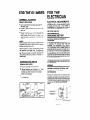
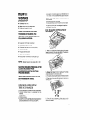
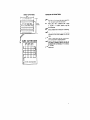
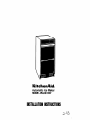
Ki+chenAid,
Automatic Ice Maker
Model 3KUIS185V
INSTALLATION
INSTRUCTIONS
a-93
CHANGING
TI-IE BIN DOOR
The slorage bin door and lower
accept
an oplional
decorative
choice.
panel are deslgned
to
wood panel of your
The wood panel should be no more than j/4 Inch (6.35
Ihick. GUI il lo the same size as Ihe production
panel. See Figure 1.
To change
the bin door
mm)
AND LOWER
DOOR
BIN
I
Tf
11 %”
(28.6 cm)
PANEL
LOWER
PANEL
11’%8”
(30.3 cm:
PANEL
DIMENSIONS
panel.
1.
Open
the bin door.
2.
Remove
the two screws
hold Ihe handle.
on lop of the door which
3.
Remove
4.
Slide
the handle.
5.
Break off the ribs on the door insulalion
for the wood thickness.
See Figure 2
the metal
6.
Slide
7.
Replace
the wood
handle
b(43.2
cm)FIGURE
panels
1
out.
panel
into
and
acraws.
the door
to allow
frame.
To change
the lower panel:
1. Hemwe
the two screws at the txttom
that hold the
lower panel assembly
to the ice maker
2.
Remove
the Iwo acraws
assembly.
3.
Slide
the metal
panels
4.
Slide
the wood
panel
5.
Replace
on the top of the pane!
REMOVE
ALL DOOR
INSULATION
RIBS TO ACCEPT
WOOD PANEL
THICKNESS
FIGURE
and spacers
01~1.
into Ihe door
frame.
the top of the panel
NOTE: Make sure the galvanized
back of the panel assembly.
2
assembly
panel
is replaced
I”
If ice maker is installed
above
altitude,
the bin and evaporator
be adjusted
to a warmer
remove
thermostat
electricity,
directions
for
turning
the
screw as shown
in the label
two
thousand
feet of
thermostats
must
setting.
Disconnect
and
follow
the
altitude
adjustment
on each thermostat.
SHIPBOARD OPERATION
When this ice cube maker is installed
aboard
a ship,
it will be necessary
to purchase
and install
a water
deflector.
This deflector
hanas between
the lower
edge of the evaporator
and the cutter
grid. It keeps
the water
flowing
over the evaporator
from spilling
into the storage
bin area. Order the necessary
parts
from your local ice maker dealer.
2
GENERAL INFORMATION
. UNPACK
2
3
l
BOTTOM
FIGURE
1
Lay
carlon
FIGURE
3
4
Set carton
See Figure
Lift carton
Remove
outside
rear
face
and
wlrh
all
break
open
botlom
upnght
four
flaps
outward.
3.
all rape and packaglng
material
and lnslde
of the cabinet.
See
the
fan
7 Loosen thumb
pan to “thumb
LOCATE UNIT
Place
unit
unobstructed,
2
Area should be well ventllaled
wth temperature
above 150 C, 600 F and below 430 C. 1100 F. Best
results are obtained
between
210 C. 700 F and
320 C. 900 F.
up and ott 01 machme.
from
Flgure
rhe
4.
emove
Ihe front grill. lake out the screws
secur1ng Ihe grlll at the botlom
and 1111It tree 01 c&net
Turn
freely
An eleclr~cal
branch
cwcuil 01 220/240
Volt, 50 Hz,
1 phase, with a 10 Amp delayed
actlon fuse or
circuit breaker.
1
3
5R
6
t0 1111
4
flaps
2
pump
drain
FLAPS
3
on
or a sump
Syslem
THIS UNIT MUST
BE
INSTALLED
IN AN
AREA
PROTECTED
FROM
THE ELEMENTS,
SUCH
AS WIND,
RAIN,
WATER
SPRAY
OR DRIP
INTERIOR
OPEN
ElIher a gravely drain
the waler 10 an exlsling
by hand
screws
right.”
lo
make
holding
cutter
terla~n
grid
4
II moves
and water
so
the fronl
to provide
side WIII be complelely
Draper air flow.
Prov~slon
lor eleclr#city
water
lions should
be delermlned.
and
drain
connec-
The unit may be closed
in on Ihe top and lhree
sndes. bul Ihe Iron1 MUST BE u”obs,r”c,ed
lor air
circulalion
and
proper
operalion.
Inslallalion
should
be such
lhal
Ihe cabinel
can be moved
lorward
lor servicing
il necessary
. LEVEL UNIT
. UTILITIES
1 After
placing
unit
in powlion.
check
to make
certain
the unit IS level side lo side and front 10
back
2
ELECTRICITY
WATER
DRAIN
I
Accurate
leveling
1s eSsenlIal
for proper
OperaliOn.
3
Unit should
be shimmed
so that it !s solld as well as
level The shims should
be of hard permanenl
type
malerlal
such as masonate
4
If required
by sanitation
Ihe floor wlh an approved
code. seal rhe cabinet
Caulking
compound
to
OBSERVE LOCAL CODES
Emch installation
1
1~ unique
but will require:
A cold water Inlet of l/4” (6.35
tubing and a shut-off valve.
mm) OD
sdi copper
3
FOR THE PLUMBER
CONNECT TO WATER
(observelocal codes)
ELECTRICAL
1
Usa U” (6.35 mm)
cold water supply.
2
Prowde
a convement
water llrw
3
Position
the rubmg so it can enter the access hole
located
in the rmht hand rear of rhe cabinet
The
tubing
should
eitend
beyond
the cabinet
fronr
when
the cabinet
IS pushed back unto posft~on
See
Figure 5.
OD soft copper
manual
tubing
shut-oil
lor the
valve
I” the
REQUIREMENTS
A 220/240 Volt, 50 Hz. 10 Amp (used electrical
supply
is required
(lime
delay
luse or circuit
breaker
is
recommended).
It is recommended
lhat a Separate
clrcuil,
serving
only this appliance
be provided.
USE
COPPER
WIRE
ONLY
RECOMMENDED
GROUNDING METHOD
ELECTRICAL
GROUND
THIS MACHINE
NOTE:
Always
purge the water
lme before
connection
to the inlet of the water
possible
water valve malfunction
maklng
the final
valve to prevent
Alter
the cabinet
II in place, bend the tubing
to meet
the connection
at the water
valve.
The garden hose
threaded
compression
fitting
II found
in the parts
bag. This joint
provides
a conventent
dlrconnect
for
service.
Sa sure the tubing
is clear of compressor.
to
prevent
rattle.
CONNECT ME DRAIN
(observelocel codes)
The unit
FOR THE
ELECTRICIAN
is provided
wth
a gravity
to insulate
drain
For your personal
salety permanently
ground this unit
in accordance
with
applicable
local
codes
and
ordinances.
It is recommended
that a separate,
permanent
ground
connection
be made lo the unit
using a green/yellow
colored,
insulated
conductor
ol
appropriate
size from agrounded
cold waler pip?: a
grounded
lead in the service panel or a properly driven
and electrically
grounded
ground rod. Do not ground
lo a gas supply pipe. Do not connect
electric
power
supply until unit is permanently
grounded.
Connect the
ground wire lo the approved
ground and then connect
lo the metal frame 01 the unit.
WIRING
line thoroughly
CONFORM
TO NATIONAL
CONFORM
TO ALL
AND ORDINANCES
LOCAL
ELECTRICAL
CODE
CODES
Remove
grill mounting
screws
for access
to motor
comoartment
and
waler
connections.
Electrical
conriections
are made lo the electrical
box which is
located al the rear or the machine.
Run permanent
type
1.6 mm d (#14) wiring through
the hole provided
in the
eletrical
box to the line screws on the terminal
board.
(See Figure 6). DO NO USE AN EXTENSION
CORD.
GROUND
4
ON
drain
The ideal installation
has a standpipe
(1 %“. 32mm
minimum)
installed
directly
below the outlet or
the drain lube. Refer lo Figure 5 (or the proper
location
of the standpipe.
It may bedeslrable
up lo drain inlet
IS REGUIRED
FIGURE
6
TERMINAL
. 1s properly
connected
to a waler supply and drain
IS properly
connected
lo electruty
A 2201240 Volt. 50
Hz. 1 phase, 10 amp fused electrIcal supply IS required
HOW IT
WORKS
l
Compressor
l
Condenser
0
0
Water
Cutler
l
NOTE:
Time
recommended
runs
fan runs
pump
gnd
runs
(clrculafes
IS warm
waler)
WHEN THE DESIRED ICE SLAB
THICKNESS IS REACHED, THE
HARVEST CYCLE BEGINS AND THE
FOLLOWlNG HAPPENS:
Evaporalor
thermostal
Compressor
keeps
Condenser
fan slops
Waler
pump
or turns
opens
NOTE:
valve
waler
grid
electrically
l
1s used only
breaker
IS
grounded
by anyone
not able to use it properly
for Ihe job it was deslgned
to perform.
malntalned
ICE MAKER
How it makes
clrcult
OPERATION
Ice:
very
slowly
slops
Water
Cutter
IS nol operated
or
IS Sallshed
opens
Intel
IS properly
l
fuse
running
HOI gas solenoid
Excess
l
. IS properly
to touch
delay
IS flushed
IS warm
Normal
1. Water IS circulated
overa freezlng plate. As the waler
freezes, minerals
m the waler are rejected. The absence
of mmerals
oroduces
a clear sheet of ice.
oul
of the drain
pan
lo the touch
herveal
cycle
takes
60 to
120
seconds.
MACHINE RESUMES FREEZING AFTER
SLAB IS RELEASED FROM
EVAPORATOR AND THE CUlllNG
PROCESS BEGINS.
WHEN THE STORAGE BIN IS FILLED,
BIN THERMOSTAT OPENS.
0
Culler
grid
remam
2. When the desired thickness
IS reached, the Ice sheet
is released
and slides on lo a culler
grid. The grid
diwdes the sheet Into mdwdual
cubes
3. The water conlalnmg
the rejected minerals
IS dramed
oul at the end of each freezlng
cycle.
4. Fresh waler then enters the machme
for the next Ice
makmg cy
on
BEFORE OPERATING
THE ICE MAKER
It IS your responslblllly
to make sure thal the ice maker:
l has
been mslalled
where
it is protected
from the
elements.
l IS localed
so lhal the front IS not blocked,
lo provide
proper aw flow.
l IS properly
leveled
l is located
in a well ventilated
area wth temperalure
above 15°C (50°F). Best resulls are oblalned
at lemperatures
between
21°C (70°F) and 32% (90-F)
5. Cubes fall Into the storage bin
Ihe ice maker shuls off automabcally
more vce IS needed
When lhe bin IS full
and reslarls
when
5
UNIT WIRING DIAGRAM
THINGS TO
REMEMBER
0
This model
grid circuit
Water
enters only during
the defrost
cycle. Therefore
the first
cycle
will
be completed
without
water in the system.
0
As the room and water
temperatures
the amount
of Ice produced
This
higher
operating
temperatures
wll
duced ice producllon
0
The unit
touches
matically
0
The storage
meltage
wll
lemperaturd.
will shut off when ice in the storage bin
the bin thermostat
well and 41
autocycle to keep the bin full.
0 -The unit
efficiently.
clean.
0
vary. so wll
means
lhat
reSull
In re.
ban
occur.
needs
Keep
IS nol refngeraled
This, loo, vanes
wth
and some
the room
good
aor clrculahon
lo perform
the front gnll and Ihe condenser
The water
syslem.
lncludlng
filler
screen
tin lhe
water
Inlet solenoid
valve.
needs
lo be cleaned
periodlcally
for good cwculahon.
Instrucllons
are
located
on the Inner door panel
OPERATING
INSTRUCTIONS
0
For complete
Use and Care
operatmg
Guide
l
Before starling,
Bakmg
Soda
quan of warm
wash
solution
waler)
0
Make
0
Turn
cenam
swtch
Ihe waler
Informallon,
refer
to lhe
OUI lnlerlor
of cablnel
with a
(2 lablespoons
soda to a
Fllnse thoroughly.
IS turned
to the “ON”
on
pos~l!on.
IMPORTANT:
Allow
for 24
wntml.
unitto
hours
If instollod
themlostat
run lor 3 hour
before
expectlnp
Ice and
bofor.
trylng
lo eet Ihe lhlcknore
above 2,ooO
adjustments.
fwt
altitude.
SW pa@
2 for
operales
al 230 Volts except for the cutter
which operates
al 10 Volls al 1 Amp.
The compressor
runs al all times except when the bin
thermostat
becomes
satisfied
and opens up. This deenergizes
the system except for the transformer
and
cutler grid.
Under
normal
operaling
conditions,
when
the
evaporator
reaches
the preset lempeialure
(-120 C,
+ 1 go F lo -1 Qo C. -30 F. depending
on thickness
of ice)
the evaporator
lhermoslal
opens. terminating
operation
of Ihe fan motor and pump molar. The hot gas solenoid
and the water valve solenoid are energized
al lhis lime
and remain so until the evaporalor
reaches
36 (30 C)
+ 2” F (.16.60 C).
CUBELLT
-I241
CUTTER
CHECK OPERATION
GRIDS
mm)
v
2”
mm)
A
CUBE CUTTER GRID
Star!
‘ON
Ihe unit by lurmng
Ihe service
swlch
and opening
the line waler valve
IO
v
NOTE
Lell IS ‘OFF” - Mddle
IS “ON”
IS ‘CLEAN’
In “CLEAN’
pos~l~on.
pump opera1es.
I/
Check
1/
water
Will not en1er pump
pan
plate gels told and machInegoes
cycle.
I/
Check for even water flow over freezIng
Unit must be level for proper
operallon.
v
Check for desired
cube thickness
and after 24
hours adjust if necessary.
Maximum
ice yield will
be obtained
with ice lhickness
at %” (13 mm) lo
5/s” (16 mm)
v
Replace
condenser
fan to make
- RIghI
only
Ihe
sura II IS revolving.
Unlll Ireezlng
8”lo a harvest
plale.
g”Il-
7
Part No. 759099
Prtnted
In U.S.A.