1
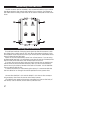
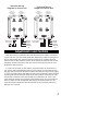
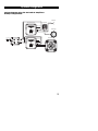
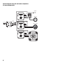
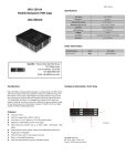
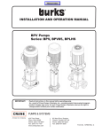
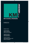
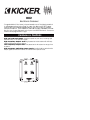
KX2
Electronic Crossover
Congratulations! You have just purchased one of the latest products
in signal processing technology to carry the famous KICKER name.
Your KICKER KX2 is designed and built to give you years of troublefree performance. This installation manual contains valuable information on how to get the most out of your new KX2 Electronic Crossover.
Thanks for buying KICKER. Enjoy!
Features & Controls
High and Low Level Inputs Speaker outputs on your deck, including high
powered units, or low level RCA signal.
High Frequency Output Jacks High passed at 18 dB/octave with infinitely
variable frequencies of 40 to 300 Hz.
Low Frequency Output Jacks Low passed at 18 dB/octave in a range of 40
to 300 Hz.
High Frequency Switching Power Supply Provide isolation and allow the
output signals to reach as much as 10 volts for lower system noise.
R
Mounting Instructons
The KX2 crossover can be mounted in any convenient location in your vehicle
that allows access to the controls and freedom from moisture. The flanges on
the chassis have mounting holes which can be used as a template for the screw
holes.
R
Wiring Instructions
The preferred method of bringing input signal into the KX2 crossover is with
RCA cables from a quality source unit, such as an aftermarket CD player. A high
level (speaker) input may also be used if your factory deck or aftermarket source
does not have low-level RCA jacks.
Power for the KX2 should always come from a fused source. If you are using
an aftermarket head unit it is convenient to tap into the sources constant power
lead for main power and add to the remote output for turn on.
If you are using a source which does not have a remote turn on lead the KX2
can be turned on with a switched accessory lead. You can find this accessory
power source in the factory harness at the back of the radio. It is the lead that
turns on and off with the key.
To reduce the chance of noise entering the system, it is recommended that
the RCA cables be run through the vehicle separate from any power wires.
Connect the CONSTANT +12V and the REMOTE +12V wires to the corresponding accessory wires from the source units factory harness.
The GROUND wire needs to be securely connected to a place on the body of
the vehicle, close to the KX2, that is clean of paint and rust.
2
Low-Level Wiring
Diagram to Source Unit
RCA's to
High Frequency
Amplifier
RCA's to
Low Frequency
Amplifier
High-Level Wiring
Diagram to Source Unit
RCA's to
High Frequency
Amplifier
R
RCA's to Low
Level Source
RCA's to
Low Frequency
Amplifier
R
GROUND
REMOTE
TURN-ON
RCA's to High
Level Source
L+
L RR+
CONSTANT
+ 12V
GROUND
REMOTE
TURN-ON
CONSTANT
+ 12V
Adjustments and Controls
After all the wiring connections are made and before the system is turned on
for the first time you must make some basic adjustments. Start by turning the HI
and LO-Pass Output Level controls most of the way down, counter-clockwise.
Now turn the HI-Pass frequency control all the way to the right and the LO-Pass
frequency control all the way to the right. Also turn the gain controls on your
amplifiers all the way down.
It is now time to power up the system. The green power LED should be lit. If
not, refer to the troubleshooting section in this manual. Turn the head unit on
and raise the volume until distortion is heard, then back the volume down slightly. This is the setting where the head unit puts out the maximum output without
sounding bad. Due to the wide range on the level controls of the KX2 you may
not be able to hear the music loud enough to tell distortion yet. If this is the
case, raise both Output Level controls to the halfway point (12 o’clock position)
and try it again. Do not increase the gain settings on the amplifiers yet. The
music will sound incomplete right now because of the preliminary frequency
settings. This is normal.
3
If your head unit is an aftermarket piece with low level outputs (RCA) which
have no more than 2 volts of output, the KX2 Output Level controls will need to
be turned all the way up to get enough signal to the amplifiers. On the other
extreme, if you are using a high powered factory or aftermarket head unit with
no RCA outputs, the Output Level controls will need to be turned down between
the minimum setting and half way up, depending on how much output signal
the unit can provide. In other words, the more output signal the unit has, the
lower the Output Level controls need to be set. The lower the output signal is
from the head unit, the higher the Output Level controls must be set.
With the amplifier gains still at minimum and the head unit as high as it will go
without distortion, raise the HI-Pass Output Level control until distortion is heard
and immediately turn it down slightly. This is the maximum setting that this gain
control should ever be set to.
Setting the HI-Pass frequency and the gain on your high frequency amplifier
will depend on the size of the amplifier and the power handling capability of
your mid/high speakers. Remember that the power handling of a midrange
speaker is directly related to the HI-Pass frequency. It will handle more power at
a higher HI-Pass frequency and less power at a lower HI-Pass frequency. If the
midrange speaker ever pops or sounds bad it is a good indication that there is
too much power going to it or that the HI-Pass frequency is set too low. Most 6
1/2” midranges will operate down to 80 or 100 Hz. A 5 1/4” or a 4” will usually
work down to 100 to 150 Hz. Most 3 1/2 mids do not like to be operated below
300 Hz.
Using these guidelines, turn the HI-Pass frequency control down to the frequency that your mid/high speakers will handle. Now you can turn the gain control up on the high pass amplifier until you reach a point where either the speakers or the amplifier just start to sound bad. Immediately turn the head unit
down to a reasonable listening level.
Continue on the LO-Pass frequency control and the low frequency amplifier
gain. Normally the LO-Pass frequency will be the same as the HI-Pass Frequency.
An exception will be when the midrange is too small to play down to a real low
frequency and the subwoofer sounds bad trying to play up to meet the
midrange. This may require a gap or difference between the high and low settings. Although not ideal, sometimes it is necessary to make the system work as
good as possible.
With the LO-Pass frequency set to match the HI-Pass or set for best sound,
turn up the LO-Pass Output Level control until the woofers start to sound bad or
lose their clear sound. It is much harder to hear distortion in a big heavy speaker
like a woofer. Now you can turn up the gain control on the low pass amplifier
until the maximum clear level is reached or until the bass level matches the
mid/high speakers. This is a subjective setting and will depend on your personal
listening preferences.
4
System Diagrams
System Diagram using the KX2 and KX Amplifiers
Bi-Amp Configuration:
Tweeter
MID/HIGH AMPLIFIER
RR+
+
_
Crossover
Other Channel
Midrange
-+-+-+
_
+
LL+
+
_
SUB AMPLIFIER
From Source
Subwoofers
RR+
Other Channel
R
LL+
_
+
5
System Diagram using the KX2 and KX Amplifiers
Tri-Amp Configuration:
Tweeter
Front Mid/ High Amp
RR+
+
_
Crossover
Other Channel
Midrange
-+-+-+
_
+
LL+
+
_
Rear Mid/ High Amp
RCA "Y"
Adapters
From Source
RR+
Other Channel
Mids/ Coaxials
R
_
LL+
+
Sub Amplifier
Subwoofers
RR+
LL+
6
Other Channel
_
+
Troubleshooting
Music is not loud enough with hea
ad unit turned up::
-Output Level controls set incorrectly
-Gain controls on amplifiers set incorrectly
See Adjustments and Controls section
Music gets loud and distorted with the heaad unit turned up pa
art wa
ay::
-Output Level controls set incorrectly
-Gain controls on amplifiers set incorrectly
See Adjustments and Controls section
Midraange speaakers pop with loud pa
assa
ages::
-HI-Pass frequency control set too low
See Adjustments and Controls section
-Too much power available at high frequency amplifier
Reduce gain setting on high frequency amplifier
One cha
annel does not operaate::
-Check the head unit balance control first
If problem stays on the same side, proceed on
-Swap left and right connections at head unit
If problem trades sides in the vehicle, then the head unit is
defective
If problem stays on the same side, proceed on
-Swap left and right connections at the input to the KX2
If problem trades sides in the vehicle, then the wiring is
defective between the head unit and the KX2
If problem stays on the same side, proceed on
-Swap left and right High Pass RCAs at output of KX2
If problem trades sides in the vehicle, then the KX2 is defective
If problem stays on the same side, proceed on
-Swap left and right High Pass RCAs at the amplifier input
If problem trades sides in vehicle, then the RCA cable between
the KX2 and the amplifier is defective
If problem stays on the same side, proceed on
-Swap left and right speaker connections at output of high pass
amplifier
If problem trades sides in the vehicle, then the amplifier is
defective
If the problem stays on the same side, then the speaker or
speaker wiring is defective
Green power indica
ator LED not on,, no sound::
-Check the CONSTANT and REMOTE (Switched) wiring connections
-Check the GROUND wiring for good connections.
7
ELECTRONICS LIMITED WARRANTY
Kicker warrants this product to be free from defects in material and workmanship under normal use
for a period of THREE (3) MONTHS from date of original purchase. When purchased from and installed
by an Authorized KICKER Dealer it is warranted for TWO (2) YEARS from date of original purchase, or
ONE (1) YEAR from date of original purchase if purchased from but not installed by an Authorized KICKER Dealer. If the product is labeled “B Stock” and purchased from an Authorized KICKER Dealer, it is warranted for ONE (1) YEAR from date of purchase, regardless of place of installation. Should service be necessary under this warranty for any reason due to manufacturing defect or malfunction during the warranty period, Kicker will replace or repair (at its discretion) the defective merchandise with equivalent
merchandise at no charge. Warranty replacements on “B-Stock” merchandise may have cosmetic scratches and blemishes. Discontinued products may be replaced with more current equivalent products.
This warranty is valid only for the original purchaser and is not extended to owners of the product
subsequent to the original purchaser. Any applicable implied warranties are limited in duration to a period
of the express warranty as provided herein beginning with the date of the original purchase at retail, and
no warranties, whether express or implied, shall apply to this product thereafter. Some states do not
allow limitations on implied warranties, therefore these exclusions may not apply to you.
This warranty gives you specific legal rights; however you may have other rights that vary from state to
state.
WHAT TO DO IF YOU NEED WARRANTY OR SERVICE
Defective merchandise must be returned to your local Authorized Stillwater Designs (Kicker) Dealer for
warranty. Assistance in locating an Authorized Dealer can be obtained by writing or calling Stillwater
Designs direct. You can confirm that a dealer is authorized by asking to see a current authorized dealer
window decal.
If it becomes necessary for you to return defective merchandise, call the Kicker Customer Service
Department at (405)624-8510 for a Return Authorization (RMA) number. Package all defective items in the
original container or in a package that will prevent shipping damage, and return to
Stillwater Designs, 5021 North Perkins Road, Stillwater, OK 74075
The RMA number must be clearly marked on the outside of the package. Return only defective components. Return of entire cabinets, system packs, pairs, etc. increases your return freight charges. Nondefective items received will be returned freight collect.
Include a dated proof-of-purchase stating the Customer name, Dealer name, product purchased
and date of purchase. Warranty expiration on items without proof-of-purchase will be determined from
type of sale and the manufacturing date code. Freight must be prepaid; items received freight collect will
be refused.
Failure to follow these steps may void your warranty. Any questions can be directed to the Kicker
Customer Service Department at (405)624-8510.
WHAT IS NOT COVERED?
•
•
•
•
•
•
This warranty is valid only if the product is used for the purpose for which it was designed.
It does not cover:
• Items previously repaired or modified by any
Damage due to improper installation
unauthorized repair facility
Subsequent damage to other components
• Return shipping on non-defective items
Damage caused by exposure to moisture,
• Products with tampered or missing barcode labels
excessive heat, chemical cleaners, and/or UV
• Products returned without a Return Authorization
radiation
(RMA) number
Damage through negligence, misuse, accident
• Freight Damage
or abuse. Repeated returns for the same
• The cost of shipping product to Kicker
damage may be considered abuse.
• Service performed by anyone other than Kicker
Any cost or expense related to the removal or
• Speaker with any foreign caulk used for gasket
reinstallation of product
material
Speakers damaged due to amplifier clipping or
distortion
HOW LONG WILL IT TAKE?
Kicker strives to maintain a goal of 24-hour service for all returns. Delays may be incurred
life lack of replacement inventory or parts is encountered.
INTERNATIONAL WARRANTY
Contact your International Kicker dealer or distributor concerning specific
procedures for your country’s warranty policies.
P.O. Box 459 • Stillwater, Oklahoma 74076 • U.S.A. • 405 624-8510
WARNING:
KICKER drivers are capable of producing sound levels that can permanently
damage your hearing! Turning up a system to a level that has audible distortion is more damaging to your ears than listening to an undistorted system at
the same volume level. The threshold of pain is always an indicator that the
sound level is too loud and may permanently damage your hearing.
Please use common sense when controlling volume!
August 2002