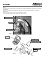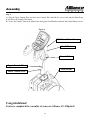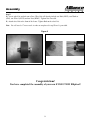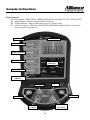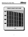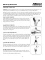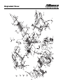
1
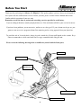
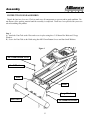
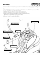
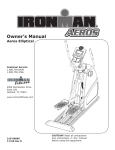
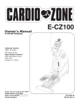
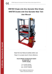
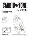
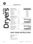
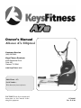
Owner’s Manual
Alliance A7e Elliptical
Customer Service
(888) 340-0482
Keys Fitness Products
4009 Distribution Drive
Suite 250
Garland, TX 75041
www.keysfitness.com
Model Name : A7e
Serial Number :
Write down for future reference
CAUTION! Read all precautions and
instructions in this manual before
using this equipment.
315-00009
Rev. E 01/06
Table of Contents
Important Safety Information
3
Before You Start
4
Assembly
5-9
Console Instructions
10-13
Monitoring Your Heart Rate
14-15
Moving Instructions
16
Warm Up Exercises
17
Parts List
18
Exploded View
19
Warranty Information
20
2
Important Safety Information
WARNING! Before using this unit or starting any exercise program, consult your physician. This is especially
important for persons over the age of 35 and/or persons with pre-existing health problems. The manufacturer
or distributor assumes no responsibility for personal injury or property damage sustained by or through the use
of this product.
WARNING! To reduce the risk of electrical shock, burns, fire, or other possible injuries to the user, it is
important to review this manual and the following precautions before operation.
SAFETY PRECAUTIONS AND TIPS
1. It is the owner's responsibility to ensure that all users of this unit have read the Owner's Manual and are
familiar with warnings and safety precautions.
2. This unit has a user maximum capacity of 350 pounds.
3. The unit should only be used on a level surface and is intended for indoor use only. The unit should not be
placed in a garage, patio, or near water and should never be used while you are wet. Keys recommends a mat
be placed under the unit to protect floor or carpet and for easier cleaning.
4. Follow safety information in regards to plugging in your unit. Do not run the power cord underneath your
unit. Do not operate the unit with a damaged or frayed power cord.
5. Wear comfortable, good-quality walking or running shoes and appropriate clothing. Do not use the unit with
bare feet, sandals, socks or stockings.
6. Always examine your unit before using to ensure all parts are in working order.
7. Allow the unit to fully stop before dismounting.
8. Pets should never be allowed near the unit.
9. Do not leave children unsupervised near or on the unit.
10. Never operate the unit where oxygen is being administered, or where aerosol products are being used.
11. Never insert any object or body parts into any opening.
12. For safety and to prevent damage to your unit, no more than one person should use the unit at a time.
13. Always unplug the unit before cleaning and/or servicing. Service to your unit should only be performed by
an authorized service representative, unless authorized and/or instructed by the manufacturer.
14. Failure to follow these instructions will void the unit warranty.
3
Before You Start
Thank you for purchasing the Alliance A7e Elliptical! This quality product you have chosen was designed to
meet your needs for cardiovascular exercise. Before you start, please read the Owner's Manual and become
familiar with the operation of your new unit.
Remember to take the time to perform the stretching exercises provided to avoid injury.
If you are taking medication, consult your physician to see if the medication will affect your exercise heart rate.
If you have heart problems, you are not active, and/or are over the age of 35 years, do not use the pre-set programs or start an exercise program without first contacting and receiving approval from your physician.
To avoid the risk of electrical shock, always keep the console dry. Do not spill liquids on the console. Keys
Fitness recommends a sealed water bottle for beverages consumed while using the unit.
Please review the following drawing below to familiarize yourself with the listed parts.
CONSOLE
WATER BOTTLE HOLDER
PULSE HANDLES
POWER
RECEPTACLE
TRANSPORT WHEELS
ADJUSTABLE FEET
4
Assembly
INSTRUCTIONS FOR ASSEMBLY:
Unpack the box in a clear area. Check to make sure all components are present and in good condition. Do
not dispose of the packing material until the assembly is completed. Tools have been provided for you to use
when assembling this product.
Step 1
A) Attach the Foot Tube to the Plate and secure in place using three 3/8*20mm Hex Bolts and 3 Large
Washers.
B) Secure the Foot Tube to the Rails using four M8*15mm Button Screws and four Small Washers.
Figure 1
M8*15mm Button Screw
Small Washers
Plate
Rails
Large Washer
Foot Tube
3/8*20mm Hex Bolts
5
Assembly
* Short screw will come installed in unit, it must be removed before this assembly step begins. See Figure 2*
Step 2
A) Insert Left Handlebar into the opening at the top of the left side on the Main Frame. Secure to the Pivot
Arm using a Small Washer and a M8*45mm Hex Bolt.
B) Slide two of the Cover Plates over the holes for the Short Screws.
C) Attach the Small Cover and secure in place using two Short Screws.
B) Slide a Grommet down the Left Handlebar and snap it onto the Main Frame.
Note: Make sure the Grommet is facing down as shown.
D) Repeat A, B, and C to complete the right side.
Figure 2
Main Frame
Left Handlebar
M8*45mm Hex Bolt
Grommet
Small Cover
Small Washer
* Short Screw *
6
Assembly
Step 3
A) Plug the Upper Console Cable, the two Pulse Wires, and the Grounding Wire into the back of the Console.
See Figure 3a
B) Secure the Console to the Console Tube and secure in place using four M5*12mm Screws and four
Small Washers.
Note: Make sure not to pinch the wire when installing the console.
C) Attach the Bottle Holder to the Console Tube using two Screws.
Upper Console Cable
Pulse Wire
Grounding Wire
Figure 3a
Console
Small Washer
M5*12mm Screw
Bottle Holder
Console Tube
Screw
Figure 3b
7
Assembly
Step 4
A) Plug the Upper Console Wire into the Lower Console Wire and slide the excess cable into the Main Frame
as you lower the Console Tube down.
B) Secure the Console Tube to the Main Frame using four Small Washers and four M8*15mm Button Screws.
Figure 4
M8*15mm Button Screws
Small Washer
Console Tube
Upper Console Wire
Main Frame
Lower Console Wire
Congratulations!
You have completed the assembly of your new Alliance A7e Elliptical!.
8
Assembly
Step 5:
A) Locate wheel kit and take out of box. Wheel kit will already include one Bolt (2D1E), two Washers
(0J4J), one Wheel (015W) and one Nut (0KMV). Tighten Nut if needed.
B) Attach wheel kit to the front of the frame. Tighten Bolt on the wheel kit.
Note: You will need a 17 mm wrench in order to complete this step.Wrench is provided.
Figure 5
Congratulations!
You have completed the assembly of your new EVOLUTION Elliptical!.
9
Console Instructions
Display Function
Data Window - TIME, SPEED, STRIDES, DISTANCE, CALORIES, PULSE, LEVEL, WATTS
Profile Window - Workout program profile and message.
Program Indicator - Indicate which program you are currently using.
Auto Scan Indicator - When this is lit, the DATA WINDOWS will automatically switch which
data is currently being displayed.
Profile Window
Data Windows
Time / Speed
Strides / Distance
Calories / Pulse
Program
Indicators
Level / Watts
Auto Scan
Indicator
Program
Select / Scan
Stop / Reset
Start / Enter
Tension Level
Up / Down
Time
Up / Down
10
Console Instructions
Starting the Console:
Plug in the power supply to power on the console.
Press START / ENTER key to go to the Quick Start Mode.
Press LEVEL UP and LEVEL DOWN for 2 sec. to go to the Service Mode.
Press TIME UP and TIME DOWN for 2 sec. to go to the Metric Unit Setting Mode.
Press the PROGRAM key to go to the Programming Mode.
After completing the program settings, press the START / ENTER to start the workout.
Stopping the Console:
The console will stop when the time counts down to zero.
Pressing the STOP / RESET key will stop the console time.
When you stop pedaling unit for 5 seconds the console will go into pause mode.
How to Reset the Console:
To reset entry data during the programming mode, press STOP / RESET key will clear the entry to
its default.
To reset console to the programming mode in the middle of a program, press STOP / RESET for 2
seconds during pause mode.
Workout Summary:
Once the program time has counted down to zero, the console will display all the last calculations
for 5 minutes presented as a workout summary. The workout summary will be terminated and
reset to its defaults if any key is pressed during the 5 minutes.
11
Console Instructions
Key Description:
START / ENTER - Press START / ENTER to start time counting or to confirm your setting while
programming the console.
SELECT / SCAN - Press SELECT / SCAN to swap the data window displays or press and hold
it for 2 seconds to alternate the displays automatically in 4 second intervals. The AUTO SCAN
indictor will be lit when the it is automatically shifting the console displays.
PROGRAM -- Press PROGRAM to select the workout program you choose. The PROGRAM
INDICATOR will be lit near the program you choose.
STOP / RESET -- Press STOP / RESET to stop the time from counting or hold it for 2 seconds to
reset your program time and the workout data to zero.
TIME UP / DOWN -- Use the TIME UP / DOWN to adjust the amount of time you wish to workout. The time range is from 0:00 to 99:59.
LEVEL UP / DOWN -- Use the LEVEL UP / DOWN to adjust the workout resistance. The resistance range is from 1 to 16, sixteen being the hardest.
Programming Mode:
1)
Use TIME UP / DOWN to enter the amount of time you wish to workout. The manual profile will
appear on the PROFILE WINDOW and the setting time will be shown on the TIME WINDOW.
2)
Press START / ENTER to confirm the workout time.
3)
USE LEVEL UP / DOWN to enter the user weight. The message “LB” or “KG” will appear on
the PROFILE WINDOW and the setting weight will be shown on the TIME WINDOW.
4)
Press START / ENTER to confirm the user weight.
5)
Use PROGRAM key to select which workout program you intend to use.
6)
Press START / ENTER and the console will start with the selected workout program and the
parameters you entered.
Quick Start Mode:
1)
Press the START / ENTER key only. The workout starts with the MANUAL program and has
a 30 minute default program time.
Using Running Mode:
1)
The console will display and update calculated workout data on each of the DATA WINDOWS.
2)
The console will continue counting the program time until it has reached zero.
3)
Use LEVEL UP / DOWN to adjust the workout resistance levels during the workout.
4)
Use SELECT / SCAN to change the data that is being displayed in the windows or press and
hold SELECT / SCAN to auto scan the displays every 4 seconds.
5)
You can change the workout program by pressing the PROGRAM key. Once the program is
selected it will begin at the beginning column but workout data windows will continue from
where they left off.
12
Console Instructions
Sleeping Mode:
The console will go into Sleeping Mode and shut off the display if there is no speed signal or key
pressed for 3 minutes.
Sleeping Mode will end if any key is press or pedaling begins.
Console Service Mode:
Display Scroll Testing will show on the PROFILE WINDOW and "0"…"9", "A"…"F" on the
DATA WINDOW, press any key to pass the testing.
Keypad Testing will show the key button test results in the PROFILE WINDOW.
Press and hold STOP / RESET key for 2 seconds to pass all the testing.
Metric Unit Setting Mode:
Press and hold TIME UP and TIME DOWN for 2 seconds to set the mode.
Press LEVEL UP or LEVEL DOWN to select the mode you want..
Press START/ENTER to save the setting.
Press and hold STOP/RESET for 2 seconds to return to idle mode.
Error Message:
The TIME window will show an "Err1" message whenever the brake motor was unable to move
to its target position within 2 seconds of powering on. If this happens the console will immediately disable any further key operations until the motor error disappears.
Turn the console power off and then on again to see the error message will disappear. If the error
message remains call Keys Fitness Technical Service for more information.
13
Monitoring Your Heart Rate
Monitoring Your Heart Rate
To obtain the greatest cardiovascular benefits from your exercise workout, it is important to work within your
target heart rate zone. The American Heart Association (AHA) defines this target as 60%-75% percent of your
maximum heart rate.
Your maximum heart rate may be roughly calculated by subtracting your age from 220. Your maximum heart
rate and aerobic capacity naturally decreases as you age. This may vary from one person to another, but use
this number to find your approximate effective target zone. For example, the maximum heart rate for an average 40 year-old is 180 bpm. The target heart rate zone is 60%-75% of 180 or 108-135 bpm. See Fitness Safety
below.
Before beginning your workout, check your normal resting heart rate. Place your fingers lightly against your
neck, or against your wrist over the main artery. After finding your pulse, count the number of beats in 10 seconds. Multiply the number of beats by six to determine your pulse rate per minute. We recommend taking your
heart rate at these times; at rest, after warming up, during your workout and two minutes into your cool down,
to accurately track your progress as it relates to better fitness.
During your first several months of exercising, the AHA recommends aiming for the lower part of the target
heart rate zone-60%, then gradually progressing up to 75%.
According to the AHA, exercising above 75% of your maximum heart rate may be too strenuous unless you
are in top physical condition. Exercising below 60% of your maximum will result in minimal cardiovascular
conditioning.
Check your pulse recovery rate – If your pulse is over 100 bpm five minutes after you stop exercising, or if
it’s higher than normal the morning after exercising, your exertion may have been too strenuous for your current fitness level. Rest and reduce the intensity next time.
Fitness Safety The target heart rate chart indicates average rate zones for different ages. A variety of different
factors (including medication, emotional state, temperature and other conditions) can affect the target heart
rate zone that is best for you. Your physician or health care professional can help you determine the exercise
intensity that is appropriate for your age and condition.
(MHR) = Maximum Heart Rate
(THR) = Target Heart Rate
220 - age = maximum heart rate (MHR)
MHR x .60 = 60% of your maximum heart rate.
MHR x .75 = 75% of your maximum heart rate.
For example, if you are 30 years old, your calculations will be as follows:
220 - 30 = 190
190 x .60 = 114 (low end or 60% of MHR)
190 x .75 = 142 (high end or 75% of MHR)
30 year-old (THR) Target Heart Rate would be 114-142
See Heart Rate Table (on next page) for additional calculations.
14
Monitoring Your Heart Rate
TARGET HEART RATE ZONE
100%
200
195
190
185
180
Serious
athletic
training range
85%
170
166
162
157
Cardiovascular
conditioning
range
75%
150
146
143
139
153
135
175
149
131
Fat burning
range
60%
120
20
117
25
114
30
111
35
108
40
105
45
AGE
15
170
145
128
102
50
165
140
124
160
136
120
99
96
55
60
155
132
116
93
65
Moving Instructions
CAUTION! TO REDUCE THE POSSIBILITY OF INJURY WHILE LIFTING, BEND YOUR LEGS AND
KEEP YOUR BACK STRAIGHT. AS YOU LEAN THE UNIT, LIFT USING YOUR LEGS, NOT YOUR
BACK.
Reach down and grab the rear Foot Tube assembly with both hands. Next, carefully tilt the unit up until it rolls
freely on the transport wheels. Using extreme caution, move the unit to the desired location. To set the unit
down, carefully lower unit onto Foot Tube assembly in a resting position. Do not attempt to move the unit
over an uneven or rough surface.
16
Warm Up Exercises
EXERCISE GUIDELINES
WARNING! Before beginning this or any exercise program, you should consult your physician. This is especially important for individuals over the age of 35 or individuals with pre-existing health problems.
Warming up prepares the body for the exercise by increasing circulation, supplying more oxygen to the muscles and raising body temperature. Begin each workout with 5 to 10 minutes of stretching and light exercise
to warm up. The photos on this page show several forms of basic stretching you may perform before your
workouts. In order to achieve an adequate warm-up, perform each stretch three times.
TOE TOUCH STRETCH
Stand bending your knees slightly and slowly bend forward from your hips.
Allow your back and shoulders to relax as you reach down toward your toes
as far as possible. Hold for 15 counts, then relax. This will stretch your hamstrings, back of knees, and back.
HAMSTRING STRETCH
Sit with one leg extended. Bring the sole of the opposite foot toward you and
rest it against the inner thigh of your extended leg. Reach toward your toes as
far as possible. Hold for 15 counts, then relax. This will stretch your hamstrings, lower back, and groin.
CALF/ACHILLES STRETCH
With one leg in front of the other, reach forward and place your hands against
a wall. Keep your back leg straight and your back foot flat on the floor. Bend
your front leg, lean forward and move your hips toward the wall. Hold for 15
counts, then relax. To cause further stretching of the Achilles tendon, bend
your back leg as well. This will stretch your calves, Achilles tendons, and
ankles.
QUADRICEPS STRETCH
With one hand against a wall for balance, reach back and grasp one foot with
your other hand. Bring your heel as close to your buttocks as possible. Hold
for 15 counts, then relax. This will stretch your quadriceps and hip muscles.
INNER THIGH STRETCH
Sit with the soles of your feet together and your knees outward. Pull your
feet toward your groin area as far as possible. Hold for 15 counts, then relax.
This will stretch your quadriceps and hip muscles.
17
Parts List
A7e Parts List Rev D
REF #
PART #
DESCRIPTION
QTY
REF #
PART #
DESCRIPTION
QTY
014X 306-00284
END CAP, 45MMX75MM RECTANGULAR END CAP
2
0K94 302-00115
CR. RE. TRUSS HD. TAPPING SCREW M5*12-16
014Y 310-00114
LEVELER
3
0K98 302-00116
CR. RE. TRUSS HD. TAPPING SCREW M3.5*18-
4
0157
306-00282
WHEEL ASSEMBLY
4
0KCB 302-00117
CR. RE. TRUSS HD. TAPPING SCREW M5*12-25
2
0158
302-00095
FLAT WASHER 8.5*32MM
2
0KDK 302-00111
CR. RE. PAN HD. SCREW M5*0.8-16MM
2
SHAFT BUSHING, OD 35MM
4
0KFE 302-00139
WASHER, OD6MM
1
015A 302-00097
4
015C 323-00142
PEDAL LEVER
1
0KFZ 302-00112
CR. RE. PAN HD. SCREW M5*0.8-125MM
1
015D 306-00293
STRAIN RELIEF
2
0KMV 302-01170
NUT, HEX HEAD, M10*1.5
2
015E
330-00039
CENTER SHAFT
2
0KMY 302-00122
HEX. NUT M8*1.25 T=6.5MM
5
LINKAGE
2
0KN1 302-00123
HEX. NUT M5*0.8 T=5MM
1
015N 302-00146
SPRING, OD17.8MMX108MM
1
0KNE 302-00124
HEX. NUT M6*1.0 T=5MM
2
015P
319-00002
ADJUSTMENT PLATE
2
0KQY 302-00135
LOCK NUT M8*1.25 T=8MM
2
015Q 302-00136
SCREW, M6-30MM (L)
2
0KR9 302-00136
SCREW, M6-30MM (L)
4
015R 311-00040
EDDY CURRENT BRAKE
1
0KRK 302-00144
U-TYPE NUT M5-12MM
4
015H 319-00003
015W 306-00291
TRANSPORTATION WHEEL, A7E
2
0KRV 302-00121
HEX. HD. NUT 3/8*26T
2
015Y 302-00096
SHAFT BUSHING, OD26MM
4
0ZLT 302-00143
WRENCH HEX. 5/16"-3 3/4"
1
0163
311-00038
POLY V-BELT PULLEY
1
10LU 310-00126
LEVELER (REAR)
2
0165
319-00001
IDLER TENSIONED PLATE
1
2195
FOAM GRIP,OD34MMX510MM LENGTH
2
0168
323-00140
PEDAL TUBE
1
21CV 310-00118
WATER BOTTLE CAGE
1
END CAP, 25.2MMX75.2 RECTANGULAR A7E,600
2
21EU 306-00376
CENTER CASE 600E A7E
1
2
016C 306-00285
310-00113
2D1E 302-01171
BOLT, HEX HEAD, M10*55MM
2
21F1
306-00292
PLATE COVER
016P
CRANK ARM
2
21F2
305-00094
COVER, LEFT W/ LOGO, A7E
1
016U 330-00040
CENTER SHAFT ASSEMBLY
1
21F3
305-00095
COVER, RIGHT W/LOGO, A7E
1
017X 306-00290
RUBBER COVER
2
21H4 314-00009
WARNING LABEL
1
018A 314-00004
600E INSTRUCTION LABEL
1
21HN 310-00115
BRAKE CABLE
1
018D 302-00098
FLAT WASHER 16*20-0.3MM
4
21MY 302-00106
FLAT WASHER 29*24*0.3MM
4
1
018E
330-00041
WRENCH, M8 HEX HD, L=108MM
1
21R6 313-00071
TRANSFORMER 600E
01HU 313-00072
302-00140
POWER SOCKET
1
23A1 307-00055
MOTOR 600E
1
01J8
REED SWITCH
1
27FK 313-00067
CONTACT HR SENSOR
2
2
313-00069
0HV4 331-00035
BALL BEARING, 6203LU, 600E
4
280K 313-00068
HAND PULSE HARNESS
0HVP 331-00036
BALL BEARING 6004ZZ ( 600E)
2
2872
GROUNDING CABLE
1
0HWC 331-00037
BALL BEARING 6005Z ( 600E)
2
28JH 310-00116
FOAM GRIP,OD31MMX125MM T=3MM
2
0J3Q 302-00141
WRENCH HEX. 5-70MM
1
28JV 323-00153
RAIL ASSEMBLY
1
0J3R
WRENCH HEX. 6-83MM
1
28JY 323-00145
LEFT HANDLEBAR ASSEMBLY
1
FLAT WASHER 5*10-1MM
1
28JZ
RIGHT MOVING HANDLE BAR ASSEMBLY
1
302-00142
0J4D 302-00099
313-00065
323-00146
0J4E
302-00100
FLAT WASHER 6*13-1MM
2
28K0 323-00154
REAR STABILIZER ASSEMBLY
1
0J4J
302-00101
FLAT WASHER 10*20-2MM
3
28K5 323-00143
CONSOLE MAST
1
0J4P
302-00102
FLAT WASHER 8*16-1.4MM
4
28K6 323-00152
LEFT PIVOT ARM
1
0J57
302-00103
FLAT WASHER 8.2*19-1.4MM
4
28K7 323-00151
RIGHT PIVOT ARM
1
0J5H 302-00138
WASHER 5.2*12-1.0MM
4
28R6 323-00308
FRAME, REVISED FOR NEW TRANS WHEEL
1
0J6C
302-00101
FLAT WASHER 10*20-2MM
4
28RP 313-00066
CONSOLE HARNESS
1
0J7F
302-00105
FLAT WASHER 5/16*7/8-5/64
4
28RQ 313-00070
WIRE HARNESS MAIN
1
0JAG 302-00137
SCREW, M5-6MM
1
28T4
306-00287
END CAP, OD31.5MM ROUND, A7E
2
0JED 302-00108
C-RING A-16
2
28T5
306-00288
END CAP, OD76MM ROUND, A7E, 600E
2
0JEG 302-00109
C-RING A-20
1
28VS 310-00119
WATER BOTTLE
1
0JEH 302-00110
C-RING A-24
2
28VT 310-00120
WATER BOTTLE ASSEMBLY
1
0JGQ 302-00147
PARALLEL KEY
2
28ZR 323-00150
LEFT PIVOT ARM ASSEMBLY
1
0JLE
BELT, POLY V BELT A7E
1
28ZS 323-00149
RIGHT PIVOT ARM ASSEMBLY
1
0JUX 302-00125
HEX. SOC. HD. CAP BOLT M8*1.25-30MM
4
28ZT 323-00147
LINKAGE ASSEMBLY
2
0JV0 302-00126
HEX. SOC. HD. CAP BOLT M8*1.25-45MM
4
28ZU 323-00148
PEDAL LEVER ASSEMBLY
1
0JV2 302-00127
HEX. SOC. HD. CAP BOLT M8*1.25-60MM
2
29Q7 306-00289
PEDAL
1
0JWJ 302-00128
HEX. SOC. HD. CAP BOLT 3/8"-16UNC-3/4inc
3
29Q8 306-00289
PEDAL
1
0JWP 302-00129
HEX. SOC. HD. CAP BOLT 3/8*16UNC-2INCH
2
2908
323-00141
PEDAL TUBE ASSEMBLY
1
0JWQ 302-00130
HEX. SOC. HD. CAP BOLT 3/8*16UNC-2"
2
2909
311-00039
IDLER PULLEY ASSEMBLY, 600e/A7e
1
0JWR 302-00120
HEX. HD. BOLT 3/8*16-3"
2
290A 313-00073
REED SWITCH ASSEMBLY
1
0JX8 302-00131
HEX. SOC. SET SCREW M6*1.0-8MM
4
290B 311-00041
POLY V-BELT PULLEY ASSEMBLY
1
0K01 302-00132
HEX. SOC. TRUSS HD. SCREW M8*1.25-15 MM
4
29ZM 307-00062
CONSOLE, A7e
1
0K03 302-00133
HEX. SOC. TRUSS HD. SCREW M8*1.25-15MM
4
29ZT 314-00011
MEDALLION KEYS
2
0K09 302-00134
HEX. SOC. TRUSS HD. SCREW M8*1.25-12MM
2
29ZU 314-00013
SHROUD LABEL (LEFT) A7E
1
304-00012
0K37 302-00118
CR.RE. PAN HD. SCREW & WASHER M5*0.8-16m
1
29ZV 314-00012
SHROUD LABEL (RIGHT) A7E
1
0K4A 302-00119
CR.RE. PAN HD. SCREW & WASHER M5*0.8-20
2
29ZW 314-00014
A7E LABEL AT SHROUD
2
0K4R 302-00145
CR.-RE. TRUSS HD. SCREW M5*0.8-12MM
4
2A00 314-00015
ALLIANCE SERIAL LABEL
1
0K7H 302-00113
CR. RE. ROUND WASHER HD. SCREW M5*0.8-25
2
OWNER'S MANUAL A7e
1
0K7N 302-00114
CR. RE. ROUND WASHER HD. SCREW M6*1.0-30
8
18
#
315-00009
Exploded View
0K7L
29Q7
016C
29AZ
2908
0168
0KMY
10LU
2198
28JY
21HW
018F
OJ57
0J57
0K0 A
0JV0
21MY
28K0
28T5
0JX8
01FD
0KNE
28ZR
0JWP
0J4P
28TG
280K
2 4 FK 2 8 T4
28JH
0KFE
0 K0 3
28VS
21CV
0J4P
28VT
018A
29B1
017X
29B4
29DW
018D
015A
21H 4
290B
0KRK
21F1
0K94
2 9B2
21R6
0K7H
0JGQ
0163
28ZT
0J4P
0KQY
0KQY
29Q 8
0158
21EU
015N
0 KD K
0JUX
016U
21K5
0157
0K09
0J7F
0HV4
0KMV
015W
0J4J
0J4P
2D1E
0KQY
231P
0J5H
0 K4 R
014X
0JLE
0KR9
2872
0 JAF
28K5
01J8
290A
28RQ
015D
OK984
0JV 2
28R6
2536
014Y
0 K 4A
0K37
0165 0HW C
0JEH
016P
23A1
0J6C
21HN
0HV P
0JEG
2909
0JWR
015R
015Q
018D
28JV
0KRV
0K09
21HV
015P
0J4J
0JW Q
0J4J
0JWJ
0 LMN
015H
0KN1
015Y
0JED
015C
28ZU
2929
0 KC B
0J4E
015E
0J4J
28K7
015Y
28JZ
01H U
0 KRK
01FE
015Y
28ZS
0KR9
0K37
2 9B3
018E
292A
0J4D
0KFZ
0ZLT
0J3R
0J3Q
19
Warranty Information
KEYS FITNESS PRODUCTS, LP LIMITED WARRANTY
PRODUCT: Alliance A7e Elliptical
HOME USE WARRANTY:
Parts: 3 Years, Electronics: 2 Years, Labor: 1 Year
LIGHT INSTITUTIONAL:
Parts: 2 Years, Electronics: 2 Years, Labor: 1 Year
This Limited Warranty applies in the United States and Canada to products manufactured or distributed by Keys Fitness Products,
LP (“Keys”) under the KEYS brand name. The warranty period to the original purchaser is listed above in the table.
Keys warrants that the Product you have purchased for use from Keys or from an authorized Keys reseller is free from defects in
materials or workmanship under normal use during the warranty period. Your sales receipt, showing the date of purchase of the
Product, is your proof of purchase. This warranty only extends to you, the original purchaser. It is not transferable to anyone who
subsequently purchases the Product from you. It excludes expendable parts (wear items). Wear items pertain to components that might
need to be replaced due to normal wear and tear. These items vary per product but will include computer overlays, pedal straps, rope
cords, seats, grips, chains, bottom bracket assemblies, pads, upholstery, pulleys, bearings, etc. Please contact a Keys Fitness customer service representative for specifics on wear items. This Limited Warranty becomes VALID ONLY if the product is purchased
through a Keys Fitness authorized dealer unless otherwise authorized by Keys Fitness in writing.
During the warranty period Keys will repair or replace (at Keys' option) the product if it becomes defective, malfunctions, or otherwise fails to conform with this Limited Warranty under normal use. In repairing the Product, Keys may replace defective parts, or at
the option of Keys, serviceable used parts that are equivalent to new parts in performance. All exchanged parts and Products
replaced under this warranty will become the property of Keys. Keys reserves the right to change manufacturers of any part to cover
any existing warranty.
This warranty DOES NOT COVER shipping charges, export taxes, custom duties and taxes, or any other charges associated with
transportation of the parts or Product.
To obtain warranty service, you must contact a Keys authorized retailer, service technician or Keys Fitness at our phone numbers
located in this manual. Any parts determined to be defective must be returned to Keys to obtain warranty service. You must prepay
any shipping charges, export taxes, custom duties and taxes, or any other charges associated with transportation of the parts or
Product. In addition, you are responsible for insuring any parts or Product shipped or returned. You assume the risk of loss during
shipment. You must present Keys with proof-of-purchase documents (including the date of purchase). Any evidence of alteration,
erasing or forgery of proof-of-purchase documents will be cause to void this Limited Warranty.
This warranty does not extend to any product not purchased from Keys or from an authorized Keys reseller. This Limited Warranty
does not extend to any Product that has been damaged or rendered defective; (a) as a result of accident, misuse, or abuse; (b) by the
use of parts not manufactured or sold by Keys; (c) by modification of the Product or normal wear and tear; (d) operation on incorrect
power supplies; or (e) as a result of service by anyone other than Keys, or an authorized Keys warranty service provider. Product on
which the serial number has been defaced or removed is not eligible for warranty service. Should any Product submitted for warranty service be found ineligible, an estimate of repair cost will be furnished and the repair will be made if requested by you upon Keys'
receipt of payment or acceptable arrangements for payment.
EXCEPT AS EXPRESSLY SET FORTH IN THIS WARRANTY, KEYS MAKES NO OTHER WARRANTIES, EXPRESSED OR
IMPLIED, INCLUDING ANY IMPLIED WARRANTIES OF MERCHANTABILITY AND FITNESS FOR A PARTICULAR PURPOSE. KEYS EXPRESSLY DISCLAIMS ALL WARRANTIES NOT STATED IN THIS LIMITED WARRANTY. ANY IMPLIED
WARRANTIES THAT MAY BE IMPOSED BY LAW ARE LIMITED TO THE TERMS OF THIS LIMITED WARRANTY. NEITHER KEYS NOR ANY OF ITS AFFILIATES SHALL BE RESPONSIBLE FOR INCIDENTAL OR CONSEQUENTIAL DAMAGES. SOME STATES DO NOT ALLOW LIMITATIONS ON HOW LONG AN IMPLIED WARRANTY LASTS OR THE
EXCLUSION OR LIMITATION OF INCIDENTAL OR CONSEQUENTIAL DAMAGES, SO THE ABOVE LIMITATIONS OR
EXCLUSION MAY NOT APPLY TO YOU. This Limited Warranty gives you specific legal rights and you may also have other
rights that may vary from state to state. This is the only express warranty applicable to Keys-branded products. Keys neither
assumes nor authorizes anyone to assume for it any other express warranty.
PLEASE SEND IN THE WARRANTY CARD WITHIN TEN (10) DAYS OF PURCHASE TO REGISTER YOUR UNIT WITH
KEYS FITNESS PRODUCTS, LP.
MAIL WARRANTY CARD TO:
KEYS FITNESS PRODUCTS, PO BOX 551239, DALLAS, TX 75355
20
Customer Service
(888) 340-0482
Keys Fitness Products
4009 Distribution Drive
Suite 250
Garland, TX 75041
www.keysfitness.com