1
7V WIDE TOUCH SCREEN MONITOR
LZ-760R
INSTRUCTION MANUAL
© B64-3159-00/00 (EV)
LZ-760R_E_(En).indd 1
05.6.7 10:29:03 AM
Contents
Before Use .................................................... 3
Monitor Control Function ........................... 4
• Power Off
• Switching the Monitor’s Picture
• Volume
• Switching the TV/Video Screen Mode
• Switching the Speaker Mode
• Switching the AV Output
• Switching to the Screen Control Screen
Screen Control Screen
• Enter the Screen Control Screen
• Adjusting the Picture Quality
• Auto Dimmer [Auto DIM]
• Exit the Screen Control Screen
On Screen Control Mode
• Switching the TV/Video Screen Mode
• Switching the Speaker Mode
• Switching the AV Output
• Exit the On Screen Mode
TV Control Function .................................. 14
On Screen Control
• Switching the Control Screen
• Selecting the Preset Band
• Seek Mode
• Selecting the Channel
Control Screen
• Selecting the Preset Band
• Seek Mode
• Selecting the Channel
• Station Preset Memory
• Auto Memory Entry
• Recalling a Preset Station
• Exit the Control Screen
Installation ................................................. 16
Troubleshooting Guide ............................. 23
Specifications............................................. 24
Setup Function ............................................ 8
• Enter the Setup Menu Screen
Setup Menu Screen
• Setting the System Setup
• Setting the TV Setup
• Setting the Touch Panel Adjustment
• Exit the Setup Menu Screen
• Initializing the User Settings
System Setup Screen-1
• Setting the NAV input
• Setting the AV-IN1 input
• Setting the AV-IN2 input
• Select the AV-IN2 input display
• Touch Sensor Tone [BEEP]
• Switching the Setup Screen-2
• Exit the System Setup Screen-1
System Setup Screen-2
• Setting the AV Output [AV-OUT]
• Switching the Setup Screen-1
• Exit the System Setup Screen-2
TV Area Setting Screen
• Setting the TV Area
• Exit the TV Area Setting Screen
Touch Panel Adjustment Screen
• Adjusting the Touch Position
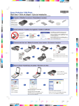
The illustrations of the display and the panel appearing in this manual are examples used to
explain more clearly how the controls are used. Therefore, what appears on the display in the
illustrations may differ from what appears on the display on the actual equipment, and some of
the illustrations on the display may represent something impossible in actual operation.
2 |
English
LZ-760R_E_(En).indd 2
05.6.7 10:29:04 AM
Before Use
Cleaning the Unit
2WARNING
To prevent injury and/or fire, take the following
precautions:
• Ensure that the unit is securely installed. Otherwise it may fly
out of place during collisions and other jolts.
• When extending the ignition, battery or ground wires,
make sure to use automotive-grade wires or other wires
with an area of 0.75mm (AWG18) or more to prevent cable
deterioration and damage to the cable coating.
• To prevent short circuits, never put or leave any metallic
objects (e.g., coins or metal tools) inside the unit.
• If the unit starts to emit smoke or strange smells, turn off the
power immediately and consult your Kenwood dealer.
• Do not touch the liquid crystal fluid if the LCD is damaged
or broken due to shock. The liquid crystal fluid may be
dangerous to your health or even fatal.
If the liquid crystal fluid from the LCD contacts your body or
clothing, wash it off with soap immediately.
If the faceplate of this unit is stained, wipe it with a dry soft
cloth such as a silicon cloth.
If the faceplate is stained badly, wipe the stain off with a cloth
moistened with neutral cleaner, then wipe neutral detergent
off.
2CAUTION
Applying spray cleaner directly to the unit may affect its
mechanical parts. Wiping the faceplate with a hard cloth or
using a volatile liquid such as thinner or alcohol may scratch
the surface or erases characters.
Screen brightness during low temperatures
When the temperature of the unit falls such as during winter,
the liquid crystal panel’s screen will become darker than usual.
Normal brightness will return after using the monitor for a
while.
2CAUTION
To prevent damage to the machine, take the
following precautions:
• Make sure to ground the unit to a negative 12V DC power
supply.
• Do not open the top or bottom covers of the unit.
• Do not install the unit in a spot exposed to direct sunlight or
excessive heat or humidity. Also avoid places with too much
dust or the possibility of water splashing.
• Do not subject the faceplate to excessive shock, as it is a
piece of precision equipment.
• When replacing a fuse, only use a new one with the
prescribed rating. Using a fuse with the wrong rating may
cause your unit to malfunction.
• To prevent short circuits when replacing a fuse, first
disconnect the wiring harness.
• Do not use any screws except for the ones provided. The use
of improper screws might result in damage to the main unit.
• You cannot view video pictures whilst the vehicle is moving.
To enjoy TV/video pictures, find a safe place to park and
engage the parking brake.
NOTE
• If you experience problems during installation, consult your
Kenwood dealer.
• If the unit does not seem to be working right, try pressing
the reset button first. If that does not solve the problem,
consult your Kenwood dealer.
Reset button
• Even if the Reset button is pressed, values set for individual
items are not cleared. To initialize set values, perform the
operation mentioned in <Initializing the User Settings>
(page 8).
English |
LZ-760R_E_(En).indd 3
3
05.6.7 10:29:04 AM
Monitor Control Function
PWR
SCRN V.SEL
MODE
Power Off
Press the [PWR] button for at least 1 second.
Power On
Press the [PWR] button.
Switching the Monitor’s Picture
Press the [V.SEL] button.
Each time the button is pressed the monitor’s
picture switches as follows:
During the KTC-V500N, KTC-V500P or KTCV500E is not connected:
Display
Picture
"Video 1"
Video 1 (AV-IN1 setting during
"Video 1")
"Video 2"/
Video 2 (AV-IN2 setting during
"R-Cam"
"Video 2" or "R-Cam")
"NAV"
Navigation (NAV setting during
"RGB" or "AV-IN1")
During the KTC-V500N, KTC-V500P or KTCV500E is connected:
Display
Picture
"Video 1"
Video 1 (AV-IN1 setting during
"Video 1")
"Video 2"/
Video 2 (AV-IN2 setting during
"R-Cam"
"Video 2" or "R-Cam")
Channel
Television
"NAV"
Navigation (NAV setting during
"RGB" or "AV-IN1")
• For "AV-IN" and "NAV" setting, refer to <System Setup
Screen-1> (☛ Page 9).
You cannot view television and video pictures whilst the
vehicle is moving. To enjoy television and video pictures,
find a safe place to park and engage the parking brake.
4 |
English
LZ-760R_E_(En).indd 4
Volume
Increasing Volume:
Press the [5] button.
Decreasing Volume:
Press the [∞] button.
Switching the TV/Video Screen Mode
Press the [MODE] button.
Each time the button is pressed the screen mode
switches as follows:
Display
Setting
"Full"
Full screen mode
"Just"
Just screen mode
"Zoom"
Zoom screen mode
"Normal"
Normal screen mode
• You cannot operate when the navigation picture is
displayed.
yyy
;;;
;;;
yyy
;;;yyy
yyy
;;;
• Normal
• Full
;;;
yyy
;;;
;;;;;;
yyy
• Just
• Zoom
05.6.7 10:29:05 AM
Switching the Speaker Mode
Press the [MODE] button for at least 1 second.
Each time the button is pressed for at least 1
second the built-in speaker mode switches as
follows:
Display
Setting
"Normal"
Sound with monitor picture
"TV"
Sound of televion (During the
KTC-V500N, KTC-V500P or KTCV500E is connected)
"NAV"
Sound of navigation
"Video1"
Sound of video 1
"Video2"/
Sound of video 2
"R-Cam"
"Off"
Built-in speaker is turned off
Switching to the Screen Control Screen
Press the [SCRN] button.
(☛ Page 6)
Switching the AV Output
Press the [V.SEL] button for at least 1 second.
Each time the button is pressed for at least 1
second the AV output switches as follows:
Display
Setting
"Normal"
Picture/sound with monitor
picture
"TV"
Picture/sound of the television
(During the KTC-V500N,
KTC-V500P or KTC-V500E is
connected)
"Video1"/
Picture/sound input from the
"NAV"
AV-IN 1 terminal
"Video2"/
Picture/sound input from the
"R-Cam"
AV-IN 2 terminal
English |
LZ-760R_E_(En).indd 5
5
05.6.7 10:29:06 AM
Screen Control Screen
Enter the Screen Control Screen
Select the Screen Control mode by referring to
"Switching to the Screen Control Screen" (page 5).
Auto Dimmer [Auto DIM]
Touch
[7On]
Adjusting the Picture Quality
Item
BRT
TIN
COL
CONT
BLK
DIM
Touch
[3]
[2]
[3]
[2]
[3]
[2]
[3]
[2]
[3]
[2]
[3]
[2]
Setting
Brighter screen
Darker screen
Stronger green level
Stronger red level
Deeper color
Paler color
Stronger contrast
Less contrast
Less black level
Stronger black level
Brighter screen
Darker screen
[7Off ]
Setting
The [DIM] level can be adjusted.
Also, when the area around the
monitor is dark, the monitor
brightness can be changed by
the [DIM] level.
The [DIM] items can’t be
adjusted. Also, even if the area
around the monitor is dark,
it can’t be changed from the
brightness set by [BRT].
Exit the Screen Control Screen
Touch the [OK] button.
• The [ TIN ] and [ COL ] cannot be adjusted for the
navigation picture or the control screen.
• The [ TIN ] cannot be adjusted for the picture of PAL.
• Separate picture quality settings can be stored for the
television, video, control screens and navigation screens.
6 |
English
LZ-760R_E_(En).indd 6
05.6.7 10:29:06 AM
Monitor Control Function
On Screen Control
D
A
B
C
When the current setting information is displayed on the screen, touching a dotted line will enable
operation of each of the following items:
• If R-Cam is selected when Mirror is set to ON for AV-IN2 (mentioned in <System Setup> (page 9)), On-screen settings
are not displayed.
Switching the TV/Video Screen Mode
Touch the A area.
When buttons are displayed, touching the A area
switches the Screen mode as follows:
Display
Setting
"Full"
Full screen mode
"Just"
Just screen mode
"Zoom"
Zoom screen mode
"Normal"
Normal screen mode
• You cannot operate when the navigation picture is
displayed.
Switching the Speaker Mode
Touch the B area.
When buttons are displayed, touching the B area
switches the built-in speaker mode as follows:
Display
Setting
"Normal"
Sound with monitor picture
"TV"
Sound of televion (During the
KTC-V500N, KTC-V500P or KTCV500E is connected)
"NAV"
Sound of navigation
"Video1"
Sound of video 1
"Video2"/
Sound of video 2
"R-Cam"
"Off"
Built-in speaker is turned off
Switching the AV Output
Touch the C area.
When buttons are displayed, touching the C area
switches the AV output mode as follows:
Display
Setting
"Normal"
Picture/sound with monitor
picture
"TV"
Picture/sound of the television
(During the KTC-V500N,
KTC-V500P or KTC-V500E is
connected)
"Video1"/
Picture/sound input from the
"NAV"
AV-IN 1 terminal
"Video2"/
Picture/sound input from the
"R-Cam"
AV-IN 2 terminal
Exit the On Screen Mode
Touch the D area.
• If you make no operation for 5 seconds, the On screen
control mode is automatically canceled.
English |
LZ-760R_E_(En).indd 7
7
05.6.7 10:29:06 AM
Setup Function
Setup Menu Screen
SCRN
Enter the Setup Menu Screen
Press the [SCRN] button for at least 1 second.
Setup Menu Screen is displayed.
Setting the System Setup
Touch the [System Setup] button.
System Setup Screen-1 is displayed. (☛ Page 9)
Setting the TV Setup
Touch the [TV Setup] button.
TV Setup Screen is displayed. (☛ Page 11)
(During the KTC-V500P or KTC-V500E is connected)
Setting the Touch Panel Adjustment
Touch the [Touch Adjust] button.
Touch Panel Adjust Screen is displayed. (☛ Page
12)
Exit the Setup Menu Screen
Touch the [Return] button.
• If you cannot select a setup menu item. Press the
[MODE] button for at least 1 second, the touch panel
position settings are reset to the factory defaults.
Initializing the User Settings
When the Setup menu is displayed, pressing the
[V.SEL] button for 1 second or longer restores the
factory set default values for individual items from
those set by the user.
8 |
English
LZ-760R_E_(En).indd 8
05.6.7 10:29:07 AM
< System Setup >
System Setup Screen-1
Setting the NAV input
[7Off ]
Setup input and switch method of the navigation
picture.
Touch
[7RGB]
[7AV-IN1]
[7Off ]
Setting
It becomes the RGB mode
setting. Operate the V.SEL
button when the image from
the navigation unit connected
to I/F terminal is shown on the
monitor.
It becomes the AV-IN1 mode
setting. Operate the V.SEL
button when the image from
the navigation unit connected
to AV-IN1 terminal is shown on
the monitor.
It becomes the Off mode
setting. Use this setting when
there’s nothing connected to
the I/F terminal.
Setting the AV-IN2 input
Setup switch method of the picture input to AV-IN
2 terminal.
Touch
[7Auto]
[7Manual]
Setting the AV-IN1 input
Setup switch method of the picture input to AV-IN
1 terminal.
Touch
[7Video 1]
[7NAV]
Setting
It becomes the video mode
setting. Operate the V.SEL
button when the image from
the device connected to AVIN1 terminal is shown on the
monitor.
It becomes the navigation
mode setting. Operate the V.SEL
button when the image from
the navigation unit connected
to AV-IN1 terminal is shown on
the monitor.
It becomes the Off mode
setting. Use this setting when
there’s nothing connected to
the AV-IN1 terminal.
[7Off ]
Setting
It becomes the auto video
mode setting. When the video
signal input to the AV-IN2
terminal, the monitor image is
switched to the image of the
device connected to the AV-IN2
terminal.
It becomes the video mode
setting. Operate the V.SEL
button when the image from
the device connected to AVIN2 terminal is shown on the
monitor.
It becomes the Off mode
setting. Use this setting when
there’s nothing connected to
the AV-IN2 terminal.
English |
LZ-760R_E_(En).indd 9
9
05.6.7 10:29:08 AM
System Setup Screen-1
Select the AV-IN2 input display
Selecting the display when this device is switched
to internal AV-IN2 terminal input source.
Touch the [Video 2] or [R-Cam] button.
Setting the Rear view camera image [Mirror]:
(AV-IN2 setting during "R-Cam")
Touch
Setting
[7On]
The image which appeares in
the camera is turned left-side
right and displayed.
[7Off ]
The image which appeares in
the camera is displayed as it is.
System Setup Screen-2
Setting the AV Output [AV-OUT]
Touch
[7Normal]
[7Video 1]/
[7NAV]
[7Video 2]/
[7R-Cam]
[7TV]
Setting
Picture/sound with monitor
picture.
Picture/sound from AV-IN1
terminal.
Picture/sound from AV-IN2
terminal.
Picture/sound from television.
(During the KTC-V500N,
KTC-V500P or KTC-V500E is
connected)
Switching the Setup Screen-1
Touch Sensor Tone [BEEP]
Setting the operation check sound (beep sound)
ON/OFF.
Touch
[7On]
[7Off ]
Setting
Touch sensor tone is turned on.
Touch sensor tone is turned off.
Touch the [ 2 ] button.
Exit the System Setup Screen-2
Touch the [Return] button.
Return to the setup menu screen.
Switching the Setup Screen-2
Touch the [ 3 ] button.
Exit the System Setup Screen-1
Touch the [Return] button.
Return to the setup menu screen.
10 |
English
LZ-760R_E_(En).indd 10
05.6.7 10:29:08 AM
< TV Setup >
Setup Function
TV Area Setting Screen
Setting the TV Area
(During the KTC-V500E is connected)
Select the area for TV broadcast viewing.
Selecting the Preset Bands:
Touch the [TV 1] or [TV 2] button.
Selecting the Reception Area:
Each time you touch the [ 2 ] or [ 3 ] button.
Select the channel setting for your country as
follows.
G1
Austria, Denmark,
Belgium, Finland,
Germany, Iceland,
Norway, Sweden,
Switzerland,
Netherlands,
Spain, Portugal,
Serbia and
Montenegro
PALB/G
G2
Albania, Italy
PALB/G
G3
Ireland,
United Kingdom
PAL-I
G4
France
SECAM
G5
Bulgaria, Czech,
Hungary, Poland,
Romania, Russia,
Slovakia
SECAM
-D/K
G6
Greece
SECAM
-B/G
Exit the TV Area Setting Screen
Touch the [Return] button.
Return to the Setup menu screen.
• Pulling out the Connection cable to the TV tuner,
settings of the TV Area will be default. Press the Reset
button and set the TV Area again if the Connection
cable is reconnected.
• The reception area can be set for two separate preset
bands TV1 and TV2.
English |
LZ-760R_E_(En).indd 11
11
05.6.7 10:29:09 AM
Before Use
< Touch Panel Adjustment >
TV Area Setting Screen
Setting the TV Area
(During the KTC-V500P is connected)
Select the area for TV broadcast viewing.
Selecting the Preset Bands:
Touch the [TV 1] or [TV 2] button.
Selecting the Reception Area:
Each time you touch the [ 2 ] or [ 3 ] button.
Select the channel setting for your country as
follows.
G1
China
PAL-D
G2
Burnei
Malaysia
Singapore
Thailand
PAL-B/G
G3
Hong Kong
PAL-I
G4
Indonesia
PAL-B/G
G5
Australia
Touch Panel Adjustment Screen
Adjusting the Touch Position
The touch panel can be adjusted if the position
touched and the operation performed do not
match.
1 Accurately touch the mark at the lower left.
2 Accurately touch the mark at the upper right.
When the mark at the upper right is touched,
the adjustment is completed and the system
setup menu screen reappears.
• If the [Cancel] button is touched without touching the
button at the lower left, the adjustment is canceled and
the screen goes back to the Setup Menu Screen.
• If the [Cancel] button is touched after touching the
button at the lower left, the button at the lower left
reappears.
• If the [Reset] button is touched, the settings are reset
to the factory defaults and the setup menu screen
reappears.
• The reception area can be set for two separate preset
bands TV1 and TV2.
Exit the TV Area Setting Screen
Touch the [Return] button.
Return to the Setup menu screen.
• Pulling out the Connection cable to the TV tuner,
settings of the TV Area will be default. Press the Reset
button and set the TV Area again if the Connection
cable is reconnected.
12 |
English
LZ-760R_E_(En).indd 12
05.6.7 10:29:09 AM
Setup Function
English |
LZ-760R_E_(En).indd 13
13
05.6.7 10:29:10 AM
Before
TV
Control
Use Function (During the KTC-V500N, KTC-V500P or KTC-V500E
On Screen Control
A
Control Screen
C
B
E
D
Selecting the Preset Band
Switching the Control Screen
Touch the D area.
Touch the [Band] button.
Each time the button is touched the preset band
switches between the TV1 and TV2.
Seek Mode
• If you make no button operation for 10 seconds, the
control screen is automatically cancelled.
Selecting the Preset Band
Touch the B area.
Each time the B area is touched the preset band
switches between the TV1 and TV2.
• If the button is not operated for 5 seconds, the Seek,
Band, and Ch indications disappear automatically.
Sets the seeking mode.
Touch the [Seek] button.
Each time the button is touched the seeking mode
switches as shown below.
Seeking mode(display)
Auto seek ("Auto1")
Preset station seek
("Auto2")
Manual ("Manual")
Operation
Automatic search for
a station.
Search in order of
the stations in the
Preset memory.
Normal manual
seeking control.
Seek Mode
Sets the seeking mode.
Touch the A area.
When the seek button is displayed, touching the A
area switches the seeking mode as follows:
Seeking mode(display)
Auto seek ("Auto1")
Preset station seek
("Auto2")
Manual ("Manual")
Selecting the Channel
Touch the [4] or [¢] button.
Operation
Automatic search for
a station.
Search in order of
the stations in the
Preset memory.
Normal manual
seeking control.
Selecting the Channel
Touch the A, E or C area.
14 |
English
LZ-760R_E_(En).indd 14
05.6.7 10:29:10 AM
is connected)
Station Preset Memory
Putting the station in the memory.
1 Select the band
Touch the [Band] button.
2 Select the channel to put in the memory
Touch the [4] or [¢] button.
Exit the Control Screen
Touch the [OK] button.
• If you make no button operation for 10 seconds, the
control screen is automatically cancelled.
3 Put the channel in the memory
Touch the [P1] — [P8] button for at least 1
seconds.
On each band, 1 station can be put in the
memory on each [P1] — [P8] button.
Auto Memory Entry
Putting stations with good reception in the
memory automatically.
1 Select the band for Auto Memory Entry
Touch the [Band] button.
2 Open Auto Memory Entry
Touch the [AME] button.
3 Do Auto Memory Entry
Touch the [4] or [¢] button.
When 8 stations that can be received are put in
the memory Auto Memory Entry closes.
• If you make no button operation for 10 seconds, the Auto
Memory Entry is automatically cancelled.
Recalling a Preset Station
1 Select the band
2 Call up the station
Touch the [P1] — [P8] button.
English |
LZ-760R_E_(En).indd 15
15
05.6.7 10:29:11 AM
Installation
Accessories
F
A
(M4 x 8 mm)
..........4
..........1
B
G
(Ø4 x 12 mm)
..........1
C
..........5
H
..........2
D
..........2
I
..........1
E
..........2
J
(Ø4 x 16 mm)
..........4
..........1
The use of any accessories except for those provided might result in damage to the unit. Make sure
only to use the accessories shipped with the unit, as shown above.
16 |
English
LZ-760R_E_(En).indd 16
05.6.7 10:29:11 AM
Installation Procedure
1. To prevent short circuits, remove the key
from the ignition and disconnect the ·
terminal of the battery.
2. Make the proper input and output cable
connections for each unit.
3. Connect the wiring harness wires in the
following order: ground, battery, ignition.
4. Connect the wiring harness connector to the
unit.
5. Install the unit in your car.
6. Reconnect the · terminal of the battery.
7. Press the reset button. (See page 3)
2WARNING
• This product is intended for use with 12V DC negative
ground power only. Do not connect it to any other power
supply.
• To prevent shorting, disconnect the battery cable from the
negative terminal of the battery during installation.
• Be sure to firmly stabilise this product. Do not install it in a
location which is not stable.
• Follow the installation and wiring procedures described in
this manual. Improper wiring or modified installation can
not only result in malfunction or damage to the unit but
may also result in an accident.
• Do not install the unit in the following locations.
• A location which interferes with the operation of the air
bag system.
• A location which is not made of plastic.
\ Installing on leather, wood or cloth may damage the
surface.
• A location subject to direct sunlight, subject to the air
from the air conditioner, or subject to moisture or high
temperature.
\ This may cause deformation of the monitor unit.
• Be sure to use the supplied screws for installation.
Using screws longer than those supplied may destroy parts
inside the unit causing it to smoke. Using screws shorter
than those supplied may cause the unit to come looks from
the installation bracket.
• If you are not going to install the unit using the supplied
monitor stand, be sure to use a commercially available
monitor stand. (Mounting holes for such a stand are located
on the bottom of the monitor unit.)
• If your car’s ignition does not come with an ACC position,
connect the ignition wires to a power source that can be
turned on and off with the ignition key. If you connect the
ignition wire to a power source that receives a constant
voltage supply, as with battery wires, the battery may die.
• If the fuse blows, first make sure that the wires have not
caused a short circuit, then replace the old fuse with one
with the same rating.
• Do not let unconnected wires or terminals touch metal
on the car or anything else conducting electricity. To
prevent short circuits do not remove the caps from unused
terminals or from the ends of the unconnected wires.
• After the unit is installed, check whether the brake lamps,
blinkers, wipers, etc. on the car are working properly.
• Insulate unconnected wires with vinyl tape or other similar
material.
• Thoroughly wipe away oil and other dirt from the
installation surface.
Please avoid installation on uneven surfaces.
• Do not install the video box unit under the carpet.
Otherwise heat build-up occurs and the unit may be
damaged.
English |
LZ-760R_E_(En).indd 17
17
05.6.7 10:29:12 AM
Before Use
Connection
Monitor Unit
Navigation Unit
FM/AM
ANTENNA
L
White
Connection cable
(Provided with the Kenwood
Navigation Unit)
White
Accessory B
Video Box Unit
AV OUTPUT
AV 2 INPUT
R
VIDEO
L
R
VIDEO
L
POWER
AV 1 INPUT
L (MONO)
R
TO MONITOR
VIDEO
TO TV TUNER
TO NAVIGATION
Black
Audio/Visual Output
Ignition cable (Red)
A
B
Battery wire (Yellow)
Accessory A
• Visual output (Yellow)
• Audio left output (White)
• Audio right output (Red)
FM/AM
ANTENNA
Audio/Visual input 2
• Visual input (Yellow)
• Audio left input (White)
• Audio right input (Red)
L
Audio/Visual input 1
• Visual input (Yellow)
• Audio left input (White)
• Audio right input (Red)
( 3A )
( 5A )
Ground cable (Black) · (To car chassis)
Parking sensor cable (Green)
C
PRK SW
To parking brake detection switch harness of car
For the sake of safety, be sure to
connect the parking sensor.
KTC-V500N/KTC-V500P/KTC-V500E (Optional)
Ignition key switch
A
TO MONITOR UNIT
Car fuse box (Main fuse)
TV ANTENNA INPUT
ACC
B
C
Connection cable (Provided with the
KTC-V500N/KTC-V500P/KTC-V500E)
+
Black
Battery
18 |
English
LZ-760R_E_(En).indd 18
05.6.7 10:29:12 AM
Before Use
Installation
Installation for Monitor Unit
■ Installation location and cleaning
Select for installation a location where the stand
can be placed completely horizontal or where the
front edge of the support (petal-shaped part) can be
attached horizontally as shown in Figure A.
Do not install in locations where the entire support
is at a diagonal such as in Figure B or where the
monitor unit is facing down such as in Figure C.
C
B
A
• Thoroughly wipe away and dust or grease from the
installation location using a cloth which has been soaked
in a neutral cleaning agent and wrung out. Attach the
stand after allowing the installation location to dry.
.
■ Affixing the Cushion
Affix the cushion to the monitor bracket.
Bracket
Accessory I
English |
LZ-760R_E_(En).indd 19
19
05.6.7 10:29:15 AM
Installation for Monitor Unit
■ Setting the Monitor Unit
1 Bend the stand support to conform to the
shape of the installation location.
2 Adjust the shape of the support so that there is
no rattling or gap when the stand is placed on
the support.
3 Peel off the protective strip from the doublesided tape on the bottom of the stand and
securely attach the stand.
• Do not attach the double-sided tape more than
once or touch the adhesive with your fingers as this
will weaken its adhesive strength.
• If the temperature of the surface of the installation
location is low, warm it up using a heater or
other means before attaching the stand. Low
temperature may weaken the adhesive strength of
the tape.
• The supplied stand is specially intended for this
product. Do not use it with another monitor.
4 Secure the stand (Accessory D) using the
Accessory D
supplied tapping screw (Accessory G).
5 After attaching the stand, allow it to sit
undisturbed for 24 hours.
6 Take care not to apply any force to the stand
during this time.
7 Fully loosen the installation screws, align the
slit on the rear of the unit with the installation
shoe and slide the monitor unit onto the stand.
8 Adjust the height, horizontal angle and vertical
angle of the monitor and securely tighten the
installation screws.
You can also adjust the monitor unit's forward
position by loosening the angle adjustment
knobs and adjusting the angle of the monitor
unit's installation stand.
Tighten
Loosen
Tighten
Loosen
Accessory G
Protective strip
Installation surface
• Attach the monitor to the bracket securely until it clicks.
20 |
English
LZ-760R_E_(En).indd 20
05.6.7 10:29:15 AM
Installation
■ Attaching the Harness Band
Secure the cable to the bracket using the supplied
harness band (Accessory J) .
Accessory J
■ Removing the Monitor Unit
Raise the Release button.
The Monitor Unit is unlocked, allowing you to
detach it.
Release button
English |
LZ-760R_E_(En).indd 21
21
05.6.7 10:29:15 AM
Installation
Installation for Video Box Unit
■ Securing to audio board
1 Use the screws (Accessory F) to fix the bracket
(Accessory C) onto both sides of Video Box
Unit.
Accessory F
Accessory C
Accessory F
2 Use screws (Accessory E) to fix Video Box Unit
onto an audio board or another.
■ Securing to pile carpet
Accessory E
;;;;;;
;;;;;;
;;;;;;
Peel the protective strips off of the velcro strips
(Accessory H), attach them to the bottom of the
Video Box Unit, and secure to the pile carpet.
.
• Please do not install the unit near the dashboard,
the rear tray, or other important components. Doing
so could lead to injury or accident should the unit
come off due to a shock and strike a person or an
important component.
Tapping screws should be used for mounting.
(Attachment with velcro strips, although easy, can
come off with a shock.).
22 |
English
LZ-760R_E_(En).indd 22
Accessory H
05.6.7 10:29:16 AM
Troubleshooting Guide
What might appear to be a malfunction in your unit may just be the result of slight
misoperation or miswiring. Before calling service, first check the following table for
possible problems.
General
?
The power does not turn ON.
✔ The fuse has blown.
☞ After checking for short circuits in the
wires, replace the fuse with one with the
same rating.
✔ The motor is not attached to the bracket securely.
☞ Attach the motor to the bracket until it clicks.
?
Nothing happens when the buttons are pressed.
✔ The computer chip in the unit is not functioning
normally.
☞ Press the reset button on the unit (page 3).
?
The screen is dark.
✔ The unit is in a location where temperature is low.
☞ If the temperature of the monitor unit
drops, the screen may appear darker
when power is first turned on due to the
characteristics of a liquid crystal panel.
Wait a while after turning power on for the
temperature to rise. Normal brightness will
return.
✔ The BRT, BLK, CONT, and other screen control levels
are too low.
☞ Adjust the BRT, BLK, CONT, and other
screen controls to obtain appropriate
illumination, or restore them to factory-set
levels with reference to <Initializing the
User Settings> (page 8).
English |
LZ-760R_E_(En).indd 23
23
05.6.7 10:29:16 AM
Specifications
Specifications subject to change without notice.
Monitor Unit
Screen size
...................................................................................................................................................................... 7.0 inches wide
154.1(W) x 87.0(H) x 177.0(Diagonal) mm
6-1/16(W) x 3-7/16(H) inches
Display system ............................................................................................................................................ Transparent TN LCD panel
Drive system .................................................................................................................................................. TFT active matrix system
Number of pixels ..................................................................................................................336,960 pixels (480 H x 234 V x RGB)
Effective pixels ...................................................................................................................................................................................... 99.99%
Pixel arrangement .......................................................................................................................................RGB striped arrangement
Back lighting Cold cathode tube
Speaker power ...................................................................................................................................................0.5 W (40 x 20 mm x 1)
Video Box Unit
Colour system ............................................................................................................................................................................... NTSC/PAL
External video input level (RCA jacks) ............................................................................................................. 1 ± 0.1 Vp-p/ 75 Ω
External audio input level (RCA jacks) .............................................................................................................................. 1 V/ 55 KΩ
Video output level (RCA jacks) ............................................................................................................................. 1 ± 0.1 Vp-p/ 75 Ω
Audio output level (RCA jacks) ................................................................................................................................................1 V/ 1 KΩ
Analog RGB input ............................................................................................................................................................... 0.7 Vp-p/ 75 Ω
General
Operating voltage ..................................................................................................................................................14.4 V DC (11 - 16 V)
Consumed Power ....................................................................................................................................................................................14 W
Operational temperature range.................................................................................................................................–10°C to +60°C
Storage temperature range .........................................................................................................................................–30°C to +80°C
Size
(Monitor unit) .........................................................................................................................................178(W) x 125(H) x 37(D) mm
7(W) x 4-15/16(H) x 1-7/16(D) inches
(Video box unit) .....................................................................................................................................188(W) x 30(H) x 144(D) mm
7-3/8(W) x 1-3/16(H) x 5-11/16(D) inches
Mass
(Monitor unit) ......................................................................................................................................................................540 g(1.19 LBS)
(Video box unit) ..................................................................................................................................................................680 g(1.50 LBS)
Although the effective pixels for the liquid crystal panel is given as 99.99% or more, 0.01% of pixels may not light or may light
incorrectly.
24 |
English
LZ-760R_E_(En).indd 24
05.6.7 10:29:17 AM